EP1029638A1 - Roboterteil mit einem Schlauchhalter - Google Patents
Roboterteil mit einem Schlauchhalter Download PDFInfo
- Publication number
- EP1029638A1 EP1029638A1 EP00103628A EP00103628A EP1029638A1 EP 1029638 A1 EP1029638 A1 EP 1029638A1 EP 00103628 A EP00103628 A EP 00103628A EP 00103628 A EP00103628 A EP 00103628A EP 1029638 A1 EP1029638 A1 EP 1029638A1
- Authority
- EP
- European Patent Office
- Prior art keywords
- robot
- hose
- part according
- robot part
- clamp
- Prior art date
- Legal status (The legal status is an assumption and is not a legal conclusion. Google has not performed a legal analysis and makes no representation as to the accuracy of the status listed.)
- Granted
Links
- 230000006835 compression Effects 0.000 description 2
- 238000007906 compression Methods 0.000 description 2
- 238000006073 displacement reaction Methods 0.000 description 2
- 238000004519 manufacturing process Methods 0.000 description 1
- 230000000717 retained effect Effects 0.000 description 1
- 230000007306 turnover Effects 0.000 description 1
Images



Classifications
-
- F—MECHANICAL ENGINEERING; LIGHTING; HEATING; WEAPONS; BLASTING
- F16—ENGINEERING ELEMENTS AND UNITS; GENERAL MEASURES FOR PRODUCING AND MAINTAINING EFFECTIVE FUNCTIONING OF MACHINES OR INSTALLATIONS; THERMAL INSULATION IN GENERAL
- F16L—PIPES; JOINTS OR FITTINGS FOR PIPES; SUPPORTS FOR PIPES, CABLES OR PROTECTIVE TUBING; MEANS FOR THERMAL INSULATION IN GENERAL
- F16L3/00—Supports for pipes, cables or protective tubing, e.g. hangers, holders, clamps, cleats, clips, brackets
- F16L3/08—Supports for pipes, cables or protective tubing, e.g. hangers, holders, clamps, cleats, clips, brackets substantially surrounding the pipe, cable or protective tubing
- F16L3/10—Supports for pipes, cables or protective tubing, e.g. hangers, holders, clamps, cleats, clips, brackets substantially surrounding the pipe, cable or protective tubing divided, i.e. with two members engaging the pipe, cable or protective tubing
- F16L3/1075—Supports for pipes, cables or protective tubing, e.g. hangers, holders, clamps, cleats, clips, brackets substantially surrounding the pipe, cable or protective tubing divided, i.e. with two members engaging the pipe, cable or protective tubing with two members, the two members being joined with a hinge on one side and fastened together on the other side
-
- B—PERFORMING OPERATIONS; TRANSPORTING
- B25—HAND TOOLS; PORTABLE POWER-DRIVEN TOOLS; MANIPULATORS
- B25J—MANIPULATORS; CHAMBERS PROVIDED WITH MANIPULATION DEVICES
- B25J19/00—Accessories fitted to manipulators, e.g. for monitoring, for viewing; Safety devices combined with or specially adapted for use in connection with manipulators
- B25J19/0025—Means for supplying energy to the end effector
Definitions
- the invention relates to a robot part such as in particular Robotic arm, robotic hand with one on a robotic hand arranged tool and with a hose holder for holding a hose for guiding in particular Cables of a robot or the like
- the hose follows the movements through a hose holder of the robot arm or the robot hand, whereby at the known version of the hose holder on the tool is firmly mounted. It is disadvantageous that the special for fixing the hose holder on the tool Holes on the tool are required, depending on the Use must be retrofitted. As a result the hose holder is in its position on the tool fixed, with a possibly necessary change of position of the Hose holder to the tool is expensive, because if necessary there are still holes to be drilled.
- the invention is therefore based on the object Avoiding the aforementioned disadvantages using a robot propose a hose holder arranged thereon, when changing the position of the hose holder to the Robotic hand easy to carry out with a secure attachment are.
- this task is performed on a robot type mentioned solved in that the hose holder (11) is axially positively fixed.
- the Form-locking element, such as a groove can be caused by the manufacturing process Turn easily and easily.
- the bracing can be in different radial Positions of the hose holder relative to the robot part, which is only by releasing the tension easy and uncomplicated change of the orientation of the Hose holder is possible without the axial Position of the hose holder is changed.
- the Hose holder is freely adjustable on the angular Robotic hand attached. All the advantages of the previous one firm fixation of the hose holder is retained.
- the robot part in particular a robot hand
- one, optionally profiled Flange plate that is completely closed or with a central opening can be formed.
- the Flange plate can be detached, as by screwing parallel to the axis be fixed.
- the tool is rigidly attached to the hand flange.
- the hose holder is a divisible clamp and a radially outward, rod-shaped extension which in particular largely in the middle of one Half of the clamps arranged, but also asymmetrical a clamp half can be arranged.
- the Divisible clamp can be used for an intended Change of position of the hose holder to the robot part loosened up and in the new position again Bracing that can also be fixed in this position a fixed connection is formed with the robot part.
- the rod-shaped extension is advantageously in one piece with one clamp half.
- the hand flange of the robotic hand is made this way is that the clamp can be freely rotated when released can be arranged.
- the Klemmsc are another advantage halves of light can be clamped by means of fasteners, with which already by loosening the fasteners Connection between the hose holder and the Robot part loosened and thus rotatable against each other are.
- rod-shaped extension Hose receptacles for holding at least one hose, the cable connects to the hose for energy supply arranged.
- the rod-shaped one is advantageous Extension in one piece with one clamp half.
- the hose holder is which is preferably at least one clamp for the hose, clamp into which the hose end is held, rotatable and fixable (clampable) arranged the rod-shaped extension. This increases the Mobility of the hose in relation to the robot part, and enables various adjustable exit angles between hand fleece and hose.
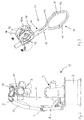
- the robot 1 of FIGS. 1 and 2 has one to one the free end of a robot hand 6, which in turn over two axes is pivotable. At the front free end the robot hand 6, a flange 7 is arranged on the a tool, not shown, can be attached.
- cables are used to supply energy to the Guided outside of the robot, the cables to Protection against damage is surrounded by a hose 8 are guided and along the outside of the robot is fixed at least selectively on this.
- the hose 8 has ribs and is with wear rings 9 and a compression spring 10, the latter him in relief with regard to robot movement in leads back to a starting point.
- the hose holder 11 is at the front end of the robot part, like the robot hand 6 against a circumferential groove axial displacement positively determined.
- the circumferential groove can be directly on the front around the A6 axis of the Robot rotatable hand part.
- This can have a flange plate 21, which by screw connections, indicated here by axial threaded holes 22 the remaining robot part can be releasably fixed.
- the flange plate 11 is, as shown, a profile part. Can be completely closed as well shown. In certain cases, a breakthrough can also occur be present through which, for example, a drive shaft leads to a hand-held tool.
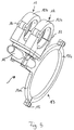
- the tube holder 11 is made of a clamp 13 in the clamp halves 13a and 13b is divisible and with the clamp half 13a one-piece, rod-shaped extension 14. How 2 can be seen, encloses the clamp 13 the flange 7 of the robot hand designed as a bearing 6 so that when tightening the as a fastener Clamp 13 trained screws 15 the clamp 13 and thus the Schlauhhalter 11 a non-positive Forms connection with the flange 7.
- the hose holder 11 can be loosened by the clamping screws 15 arbitrarily rotated on the flange 7 and in one freely selectable rotational position can be determined by friction.
- the hose 8 is on the hose holder 11 by means of two Holding clamps 12 fixed, as shown in Fig. 3 is, the holding clamps are 12 hinged clamps.
- a joint 16 12a, 12b on by a closure 17, such as a snap lock can be connected and closed, using a cable-routing hose (not shown) take up.
- clamps 12 are in turn in any rotational position on the rod 14 fixable.
- clamp halves 25a are arranged in parallel Threaded holes (not shown) provided in the Screws 26 through the clamp half 25b pass through and are screwable.
Landscapes
- Engineering & Computer Science (AREA)
- Mechanical Engineering (AREA)
- General Engineering & Computer Science (AREA)
- Robotics (AREA)
- Supports For Pipes And Cables (AREA)
- Manipulator (AREA)
Abstract
Description
- Fig. 1
- einen Roboter in Seitenansicht;
- Fig. 2
- den Roboter in Stirnansicht entsprechend dem Pfeil II in Fig. 1 und;
- Fig. 3
- einen Schnitt durch eine Flanschplatte mit aufgesetztem Schlauchhalter (von dem lediglich die Klemmschellenteile dargestellt sind);
- Fig. 4
- einen Schlauchhalter in perspektivischerr Darstellung;
- Fig. 5
- eine bevorzugte Ausgestaltung des Schlauchhalters in perspektivischer Darstellung zur Verdeutlichung der kraftschlüssigen Festlegung der Spannstellen für den Schlauch am stabförmigen Fortsatz des Schlauchhalters; und
- Fig. 6
- eine Seitenansicht auf den Schlauchhalter der Fig. 5.
- 1
- Roboter
- 2
- Sockel
- 3
- Roboterbasis
- 4
- Schwinge
- 5
- Roboterarm
- 6
- Roboterhand/Roboterteil
- 7
- Flansch/Lager
- 8
- Schlauch
- 9
- Verschleißringe
- 10
- Druckfeder
- 11
- Schlauchhalter
- 12
- Schellen
- 13
- Klemmschelle
- 13a,b
- Klemmschellenhälfte
- 14
- stabförmiger Fortsatz
- 15
- Klemmschrauben/Befestigungsmittel
- 16
- Kippgelenk
- 17
- Verschluß
- 21
- Flanschplatte
- 22
- Gewindebohrung
- 23
- Umfangsnut
- 24
- Platte
- 25
- Klemmschelle
- 25a,b
- Spannschellenhälfte
- 26
- Schrauben
Claims (14)
- Roboterteil, wie insbesondere Roboterarm, Roboterhand, mit einem an einer Roboterhand angeordneten Werkzeug und mit einem Schlauchhalter zum Halten eines Schlauches zur Führung insbesondere von Kabeln eines Roboters, oder dgl., dadurch gekennzeichnet, daß der Schlauchhalter (11) axial formschlüssig festgelegt ist.
- Roboterteil nach Anspruch 1, dadurch gekennzeichnet, daß zum Halten und angularen Verstellen des Schlauchhalters (11) eine ringförmige Führung (23) vorgesehen ist.
- Roboterteil nach Anspruch 1 oder 2, gekennzeichnet durch eine Umfangsnut (23), in der der Schlauchhalter (11) festgespannt ist.
- Roboterteil nach einem der Ansprüche 1 bis 3, gekennzeichnet durch einen Handflansch (21), an dem die axiale Festlegung erfolgt.
- Roboterteil nach Anspruch 4, dadurch gekennzeichnet, daß der Handflansch (21) durch axiale Verschraubungen (22) lösbar befestigt ist.
- Roboterteil nach einem der Ansprüche 1 bis 5, dadurch gekennzeichnet, daß der Schlauchhalter (11) zur Festlegung am Roboterteil (7, 21) eine geteilte Klemmschelle (13) aufweist, die in der Führung (23) festspannbar ist.
- Roboterteil nach einem der Ansprüche 1 bis 6, dadurch gekennzeichnet, daß der Schlauchhalter (11) einen radial nach außen gerichteten stabförmigen Fortsatz (14) aufweist.
- Roboterteil nach Anspruch 7, dadurch gekennzeichnet, daß der stabförmige Fortsatz (14) einstückig mit einer Klemmschellenhälfte (13a) der Klemmschelle (13) ist.
- Roboterteil nach einem der Ansprüche 1 bis 8, dadurch gekennzeichnet, daß ein Lager (7) zur Anordnung der Klemmschelle (13) in einer durch Drehen frei wählbaren Position vorgesehen ist.
- Roboterteil nach einem der Ansprüche 1 bis 9, dadurch gekennzeichnet, daß die Klemmschellenhälften (13a,13b) durch Befestigungsmittel (15) klemmbar sind.
- Roboterteil nach einem der Ansprüche 1 bis 10, dadurch gekennzeichnet, daß der Schlauchhalter (11) auch Aufnahmen (12) zur Aufnahme von Schläuchen aufweist.
- Roboterteil nach Anspruch 11, dadurch gekennzeichnet, daß eine Schlauchaufnahme (12) durch Halteschellen für die Schläuche gebildet ist.
- Roboterteil nach Anspruch 11 oder 12, dadurch gekennzeichnet, daß die Schlauchaufnahme (12) lösbar am stabförmigen Fortsatz (14) des Schlauchhalters (11) befestigt ist.
- Roboterteil nach einem der Ansprüche 11 bis 13, dadurch gekennzeichnet, daß die Schlauchaufnahme (12) kraftschlüssig am stabförmigen Fortsatz (14) festgelegt ist.
Priority Applications (1)
| Application Number | Priority Date | Filing Date | Title |
|---|---|---|---|
| DE20022990U DE20022990U1 (de) | 1999-02-19 | 2000-02-21 | Roboterteil |
Applications Claiming Priority (2)
| Application Number | Priority Date | Filing Date | Title |
|---|---|---|---|
| DE29902947U DE29902947U1 (de) | 1999-02-19 | 1999-02-19 | Roboterteil |
| DE29902947U | 1999-02-19 |
Publications (2)
| Publication Number | Publication Date |
|---|---|
| EP1029638A1 true EP1029638A1 (de) | 2000-08-23 |
| EP1029638B1 EP1029638B1 (de) | 2005-05-25 |
Family
ID=8069620
Family Applications (1)
| Application Number | Title | Priority Date | Filing Date |
|---|---|---|---|
| EP00103628A Expired - Lifetime EP1029638B1 (de) | 1999-02-19 | 2000-02-21 | Roboterteil mit einem Schlauchhalter |
Country Status (2)
| Country | Link |
|---|---|
| EP (1) | EP1029638B1 (de) |
| DE (2) | DE29902947U1 (de) |
Cited By (8)
| Publication number | Priority date | Publication date | Assignee | Title |
|---|---|---|---|---|
| EP1252979A1 (de) * | 2001-04-28 | 2002-10-30 | KUKA Roboter GmbH | Haltevorrichtung zum Halten von Kabeln an einem Roboterteil mit Rastelementen |
| EP1510704A1 (de) * | 2003-08-29 | 2005-03-02 | KUKA Roboter GmbH | Befestigungsvorrichtung |
| FR2881072A1 (fr) * | 2005-01-26 | 2006-07-28 | Cimlec Ind Sa | Dispositif de guidage d'un faisceau d'alimentation d'organe terminal effecteur |
| EP1163985B1 (de) * | 2000-05-27 | 2008-07-30 | KUKA Roboter GmbH | Handflansch einer Roboterhand mit einem Anbauteil zur Aufnahme eines Hilfgeräts |
| CN104626137A (zh) * | 2013-11-13 | 2015-05-20 | 沈阳新松机器人自动化股份有限公司 | 工业机器人末端执行器走线结构 |
| CN106737866A (zh) * | 2017-01-10 | 2017-05-31 | 清华大学天津高端装备研究院 | 一种适用于机器人执行器的线缆约束装置 |
| CN110561473A (zh) * | 2019-09-19 | 2019-12-13 | 佛山职业技术学院 | 一种可防线束滑落的机械手 |
| CN110573780A (zh) * | 2017-03-31 | 2019-12-13 | 莱尼电缆有限责任公司 | 用于紧固到工业机器人臂的供应软管和/或供电管线的紧固设备 |
Families Citing this family (5)
| Publication number | Priority date | Publication date | Assignee | Title |
|---|---|---|---|---|
| SE0002654D0 (sv) | 2000-07-14 | 2000-07-14 | Abb Ab | Manipulator |
| DE10231724B4 (de) * | 2002-07-13 | 2004-05-13 | Kuka Roboter Gmbh | Halteschelle |
| DE102012002093A1 (de) * | 2012-02-06 | 2013-08-08 | Deckel Maho Pfronten Gmbh | Leitungsführungssystem zur Aufnahme und Führung von Versorgungsleitungen sowie Werkzeugmaschine |
| US10427252B2 (en) * | 2014-05-09 | 2019-10-01 | Esab Ab | Ergonomic welding arm with a plurality of arm links and joints |
| DE102020125385B4 (de) | 2020-09-29 | 2026-03-12 | Murrplastik Systemtechnik Gmbh | Vorrichtung zur Befestigung eines Leitungspakets |
Citations (3)
| Publication number | Priority date | Publication date | Assignee | Title |
|---|---|---|---|---|
| DE3434899A1 (de) * | 1983-10-19 | 1985-05-23 | Kuka Schweissanlagen + Roboter Gmbh, 8900 Augsburg | Vorrichtung zum aussenseitigen halten und fuehren von versorgungsleitungen zu bewegten werkzeugen von manipulatoren |
| US5816736A (en) * | 1997-03-20 | 1998-10-06 | Flex-Cable, Inc. | Robot arm assembly |
| DE29908623U1 (de) * | 1999-05-15 | 1999-07-29 | Kuka Roboter GmbH, 86165 Augsburg | Haltearm für Energiezuführung |
Family Cites Families (1)
| Publication number | Priority date | Publication date | Assignee | Title |
|---|---|---|---|---|
| DE8330107U1 (de) | 1983-10-19 | 1984-01-26 | Kuka Schweissanlagen + Roboter Gmbh, 8900 Augsburg | Vorrichtung zum aussenseitigen halten und fuehren von versorgungsleitungen zu bewegten werkzeugen von manipulatoren |
-
1999
- 1999-02-19 DE DE29902947U patent/DE29902947U1/de not_active Expired - Lifetime
-
2000
- 2000-02-21 EP EP00103628A patent/EP1029638B1/de not_active Expired - Lifetime
- 2000-02-21 DE DE50010370T patent/DE50010370D1/de not_active Expired - Lifetime
Patent Citations (3)
| Publication number | Priority date | Publication date | Assignee | Title |
|---|---|---|---|---|
| DE3434899A1 (de) * | 1983-10-19 | 1985-05-23 | Kuka Schweissanlagen + Roboter Gmbh, 8900 Augsburg | Vorrichtung zum aussenseitigen halten und fuehren von versorgungsleitungen zu bewegten werkzeugen von manipulatoren |
| US5816736A (en) * | 1997-03-20 | 1998-10-06 | Flex-Cable, Inc. | Robot arm assembly |
| DE29908623U1 (de) * | 1999-05-15 | 1999-07-29 | Kuka Roboter GmbH, 86165 Augsburg | Haltearm für Energiezuführung |
Cited By (9)
| Publication number | Priority date | Publication date | Assignee | Title |
|---|---|---|---|---|
| EP1163985B1 (de) * | 2000-05-27 | 2008-07-30 | KUKA Roboter GmbH | Handflansch einer Roboterhand mit einem Anbauteil zur Aufnahme eines Hilfgeräts |
| EP1252979A1 (de) * | 2001-04-28 | 2002-10-30 | KUKA Roboter GmbH | Haltevorrichtung zum Halten von Kabeln an einem Roboterteil mit Rastelementen |
| EP1510704A1 (de) * | 2003-08-29 | 2005-03-02 | KUKA Roboter GmbH | Befestigungsvorrichtung |
| FR2881072A1 (fr) * | 2005-01-26 | 2006-07-28 | Cimlec Ind Sa | Dispositif de guidage d'un faisceau d'alimentation d'organe terminal effecteur |
| CN104626137A (zh) * | 2013-11-13 | 2015-05-20 | 沈阳新松机器人自动化股份有限公司 | 工业机器人末端执行器走线结构 |
| CN106737866A (zh) * | 2017-01-10 | 2017-05-31 | 清华大学天津高端装备研究院 | 一种适用于机器人执行器的线缆约束装置 |
| CN110573780A (zh) * | 2017-03-31 | 2019-12-13 | 莱尼电缆有限责任公司 | 用于紧固到工业机器人臂的供应软管和/或供电管线的紧固设备 |
| CN110561473A (zh) * | 2019-09-19 | 2019-12-13 | 佛山职业技术学院 | 一种可防线束滑落的机械手 |
| CN110561473B (zh) * | 2019-09-19 | 2024-04-23 | 佛山职业技术学院 | 一种可防线束滑落的机械手 |
Also Published As
| Publication number | Publication date |
|---|---|
| DE50010370D1 (de) | 2005-06-30 |
| EP1029638B1 (de) | 2005-05-25 |
| DE29902947U1 (de) | 1999-07-08 |
Similar Documents
| Publication | Publication Date | Title |
|---|---|---|
| DE2740356C2 (de) | ||
| DE4200905A1 (de) | Implantat zur ausrichtung und fixierung zweier knochen oder knochenteile zueinander, insbesondere spondylodese-implantat | |
| EP1029638B1 (de) | Roboterteil mit einem Schlauchhalter | |
| EP0713018A1 (de) | Verbindungsanordnung | |
| DE202008009394U1 (de) | Vorrichtung zum lösbaren Verschließen des Endes eines Rohres | |
| DE1491029A1 (de) | Zahnaertzliches Handstueck | |
| DE19750251A1 (de) | Kettenförmige Rohrschelle | |
| DE3142474C2 (de) | ||
| DE20022990U1 (de) | Roboterteil | |
| DE102013013776B4 (de) | Trägerelement für eine Schraubzwinge und Schraubzwinge | |
| EP1367312B1 (de) | Drehknopf zum Feststellen eines Geräteträgers | |
| EP1344605B1 (de) | Spannwerkzeug | |
| DE4244895C2 (de) | Vorrichtung zur Halterung von Bügelschlössern und dergleichen an Zweirädern | |
| DE3520237A1 (de) | Befestigungseinrichtung fuer zweiradlampen | |
| DE2711993A1 (de) | Gelaender- und haltestangenanordnung | |
| DE202006005375U1 (de) | Vorrichtung zum Justieren eines Baukörpers | |
| EP0784165B1 (de) | Seilspannvorrichtung | |
| DE4401478C2 (de) | Vorrichtung zum Festlegen von Bauteilen | |
| DE2504159A1 (de) | Halterung fuer gelenkarmmarkisen | |
| EP1245200A2 (de) | Bissgabelträger mit Zentralklemmung | |
| DE3019914A1 (de) | Handgeraet mit einer haltevorrichtung fuer einen seitenhandgriff | |
| DE102025117751A1 (de) | Verteileranordnung | |
| DE102022110346A1 (de) | Feuerwaffe und Anordnung zur Befestigung eines Handschutzes | |
| DE202004014426U1 (de) | Vorrichtung zum Ausziehen eines Zylinderrohres | |
| DE19910769A1 (de) | Eindrehwerkzeug für einen Luftschicht-Schraubanker |
Legal Events
| Date | Code | Title | Description |
|---|---|---|---|
| PUAI | Public reference made under article 153(3) epc to a published international application that has entered the european phase |
Free format text: ORIGINAL CODE: 0009012 |
|
| AK | Designated contracting states |
Kind code of ref document: A1 Designated state(s): DE FR GB IT SE |
|
| AX | Request for extension of the european patent |
Free format text: AL;LT;LV;MK;RO;SI |
|
| 17P | Request for examination filed |
Effective date: 20000803 |
|
| AKX | Designation fees paid |
Free format text: DE FR GB IT SE |
|
| 17Q | First examination report despatched |
Effective date: 20010921 |
|
| GRAP | Despatch of communication of intention to grant a patent |
Free format text: ORIGINAL CODE: EPIDOSNIGR1 |
|
| GRAS | Grant fee paid |
Free format text: ORIGINAL CODE: EPIDOSNIGR3 |
|
| GRAA | (expected) grant |
Free format text: ORIGINAL CODE: 0009210 |
|
| AK | Designated contracting states |
Kind code of ref document: B1 Designated state(s): DE FR GB IT SE |
|
| REG | Reference to a national code |
Ref country code: GB Ref legal event code: FG4D Free format text: NOT ENGLISH |
|
| REF | Corresponds to: |
Ref document number: 50010370 Country of ref document: DE Date of ref document: 20050630 Kind code of ref document: P |
|
| REG | Reference to a national code |
Ref country code: SE Ref legal event code: TRGR |
|
| GBT | Gb: translation of ep patent filed (gb section 77(6)(a)/1977) |
Effective date: 20050725 |
|
| ET | Fr: translation filed | ||
| PLBE | No opposition filed within time limit |
Free format text: ORIGINAL CODE: 0009261 |
|
| STAA | Information on the status of an ep patent application or granted ep patent |
Free format text: STATUS: NO OPPOSITION FILED WITHIN TIME LIMIT |
|
| 26N | No opposition filed |
Effective date: 20060228 |
|
| PGFP | Annual fee paid to national office [announced via postgrant information from national office to epo] |
Ref country code: GB Payment date: 20090217 Year of fee payment: 10 |
|
| PGFP | Annual fee paid to national office [announced via postgrant information from national office to epo] |
Ref country code: IT Payment date: 20090213 Year of fee payment: 10 |
|
| GBPC | Gb: european patent ceased through non-payment of renewal fee |
Effective date: 20100221 |
|
| PG25 | Lapsed in a contracting state [announced via postgrant information from national office to epo] |
Ref country code: GB Free format text: LAPSE BECAUSE OF NON-PAYMENT OF DUE FEES Effective date: 20100221 Ref country code: IT Free format text: LAPSE BECAUSE OF NON-PAYMENT OF DUE FEES Effective date: 20100221 |
|
| REG | Reference to a national code |
Ref country code: DE Ref legal event code: R082 Ref document number: 50010370 Country of ref document: DE |
|
| REG | Reference to a national code |
Ref country code: FR Ref legal event code: PLFP Year of fee payment: 17 |
|
| REG | Reference to a national code |
Ref country code: FR Ref legal event code: PLFP Year of fee payment: 18 |
|
| REG | Reference to a national code |
Ref country code: FR Ref legal event code: PLFP Year of fee payment: 19 |
|
| REG | Reference to a national code |
Ref country code: DE Ref legal event code: R081 Ref document number: 50010370 Country of ref document: DE Owner name: KUKA DEUTSCHLAND GMBH, DE Free format text: FORMER OWNER: KUKA ROBOTER GMBH, 86165 AUGSBURG, DE |
|
| PGFP | Annual fee paid to national office [announced via postgrant information from national office to epo] |
Ref country code: FR Payment date: 20190111 Year of fee payment: 20 Ref country code: DE Payment date: 20190205 Year of fee payment: 20 |
|
| PGFP | Annual fee paid to national office [announced via postgrant information from national office to epo] |
Ref country code: SE Payment date: 20190212 Year of fee payment: 20 |
|
| REG | Reference to a national code |
Ref country code: DE Ref legal event code: R071 Ref document number: 50010370 Country of ref document: DE |
|
| REG | Reference to a national code |
Ref country code: SE Ref legal event code: EUG |