EP1029387B1 - Crimpwerkzeug - Google Patents
Crimpwerkzeug Download PDFInfo
- Publication number
- EP1029387B1 EP1029387B1 EP98965073A EP98965073A EP1029387B1 EP 1029387 B1 EP1029387 B1 EP 1029387B1 EP 98965073 A EP98965073 A EP 98965073A EP 98965073 A EP98965073 A EP 98965073A EP 1029387 B1 EP1029387 B1 EP 1029387B1
- Authority
- EP
- European Patent Office
- Prior art keywords
- crimping tool
- screw
- tool according
- basic body
- crimp contacts
- Prior art date
- Legal status (The legal status is an assumption and is not a legal conclusion. Google has not performed a legal analysis and makes no representation as to the accuracy of the status listed.)
- Expired - Lifetime
Links
- 238000002788 crimping Methods 0.000 title claims description 57
- 230000008878 coupling Effects 0.000 claims description 16
- 238000010168 coupling process Methods 0.000 claims description 16
- 238000005859 coupling reaction Methods 0.000 claims description 16
- 230000015572 biosynthetic process Effects 0.000 description 4
- 230000033001 locomotion Effects 0.000 description 4
- 238000013461 design Methods 0.000 description 3
- 238000011161 development Methods 0.000 description 2
- 230000018109 developmental process Effects 0.000 description 2
- 230000007774 longterm Effects 0.000 description 2
- 238000000034 method Methods 0.000 description 2
- 238000012545 processing Methods 0.000 description 2
- 230000006978 adaptation Effects 0.000 description 1
- 239000004020 conductor Substances 0.000 description 1
- 238000011109 contamination Methods 0.000 description 1
- 238000005553 drilling Methods 0.000 description 1
- 230000002349 favourable effect Effects 0.000 description 1
- 230000001771 impaired effect Effects 0.000 description 1
- 239000000463 material Substances 0.000 description 1
- 238000012549 training Methods 0.000 description 1
- 238000012546 transfer Methods 0.000 description 1
Images


Classifications
-
- H—ELECTRICITY
- H01—ELECTRIC ELEMENTS
- H01R—ELECTRICALLY-CONDUCTIVE CONNECTIONS; STRUCTURAL ASSOCIATIONS OF A PLURALITY OF MUTUALLY-INSULATED ELECTRICAL CONNECTING ELEMENTS; COUPLING DEVICES; CURRENT COLLECTORS
- H01R43/00—Apparatus or processes specially adapted for manufacturing, assembling, maintaining, or repairing of line connectors or current collectors or for joining electric conductors
- H01R43/04—Apparatus or processes specially adapted for manufacturing, assembling, maintaining, or repairing of line connectors or current collectors or for joining electric conductors for forming connections by deformation, e.g. crimping tool
- H01R43/048—Crimping apparatus or processes
- H01R43/055—Crimping apparatus or processes with contact member feeding mechanism
-
- Y—GENERAL TAGGING OF NEW TECHNOLOGICAL DEVELOPMENTS; GENERAL TAGGING OF CROSS-SECTIONAL TECHNOLOGIES SPANNING OVER SEVERAL SECTIONS OF THE IPC; TECHNICAL SUBJECTS COVERED BY FORMER USPC CROSS-REFERENCE ART COLLECTIONS [XRACs] AND DIGESTS
- Y10—TECHNICAL SUBJECTS COVERED BY FORMER USPC
- Y10S—TECHNICAL SUBJECTS COVERED BY FORMER USPC CROSS-REFERENCE ART COLLECTIONS [XRACs] AND DIGESTS
- Y10S72/00—Metal deforming
- Y10S72/712—Electrical terminal crimper
-
- Y—GENERAL TAGGING OF NEW TECHNOLOGICAL DEVELOPMENTS; GENERAL TAGGING OF CROSS-SECTIONAL TECHNOLOGIES SPANNING OVER SEVERAL SECTIONS OF THE IPC; TECHNICAL SUBJECTS COVERED BY FORMER USPC CROSS-REFERENCE ART COLLECTIONS [XRACs] AND DIGESTS
- Y10—TECHNICAL SUBJECTS COVERED BY FORMER USPC
- Y10T—TECHNICAL SUBJECTS COVERED BY FORMER US CLASSIFICATION
- Y10T29/00—Metal working
- Y10T29/49—Method of mechanical manufacture
- Y10T29/49002—Electrical device making
- Y10T29/49117—Conductor or circuit manufacturing
- Y10T29/49174—Assembling terminal to elongated conductor
- Y10T29/49181—Assembling terminal to elongated conductor by deforming
- Y10T29/49185—Assembling terminal to elongated conductor by deforming of terminal
-
- Y—GENERAL TAGGING OF NEW TECHNOLOGICAL DEVELOPMENTS; GENERAL TAGGING OF CROSS-SECTIONAL TECHNOLOGIES SPANNING OVER SEVERAL SECTIONS OF THE IPC; TECHNICAL SUBJECTS COVERED BY FORMER USPC CROSS-REFERENCE ART COLLECTIONS [XRACs] AND DIGESTS
- Y10—TECHNICAL SUBJECTS COVERED BY FORMER USPC
- Y10T—TECHNICAL SUBJECTS COVERED BY FORMER US CLASSIFICATION
- Y10T29/00—Metal working
- Y10T29/53—Means to assemble or disassemble
- Y10T29/5313—Means to assemble electrical device
- Y10T29/532—Conductor
- Y10T29/53209—Terminal or connector
- Y10T29/53213—Assembled to wire-type conductor
- Y10T29/53235—Means to fasten by deformation
Definitions
- the invention relates to a crimping tool for crimping crimp contacts, in particular of crimp contacts in tape form, with a pressing device comprising Base body and a table assigned to the base body for guidance of the crimp contacts, the crimp contacts being fed to the pressing device via the table and the position of the table relative to the base body along a tour is changeable.
- the invention relates to a crimping tool for crimping crimp contacts, especially of crimp contacts in tape form, with a pressing device comprehensive base body and a table assigned to the base body to guide the crimp contacts, the crimp contacts of the pressing device be fed to the table.
- Crimping tools of the type in question have long been known in practice and exist in a wide variety of embodiments.
- the known crimping tools are designed for the efficient processing of crimp contacts in tape form, in longitudinal or transverse transport or for sortable individual contacts.
- the known crimping tools are often designed as quick-change tools and can be used on individual workstations or fully automatic machines and transfer lines.
- the processing of electrical conductors with a cross-sectional area of approximately 0.08 mm 2 to 50 mm 2 is possible.
- the table is formed in two in the base body Grooves.
- the table is fixed relative to the base body using clamping screws.
- the Clamping screws are loosened first, then the position of the table adjusted and finally the clamping screws are tightened again.
- the adjusting mechanism of the known crimping tool comprises a mounting block 78, which is fastened to the base body 12 of the crimping tool.
- the assembly block 78 has a passage 86 through which an adjusting screw 92 passes is.
- the adjusting screw 92 is in a in the table 70 of the known crimping tool trained thread 90 screwed. By turning the screw 92 is the table 70 is displaceable perpendicular to the feed direction of the crimp contacts, wherein an elastic means 81 is arranged between the mounting block 78 and the table 70 is that the screw 92 by means of the table 70 against one on the mounting block 78 trained stop 88 presses.
- the screw 92 To adjust the screw 92, it is necessary that the screw 92 on her the screw head 95 facing away from a projection 96 with reduced Has diameter.
- the protrusion has a slot 98 for engagement with, for example a screwdriver. The movement of the screw 92 takes place exclusively via the projection 96, since the screw head 95 of the screw 92 is not accessible when the crimping tool is assembled.
- the adjusting mechanism known from the D1 is complex because it is a specially designed one Mounting block 78 and a specially designed screw 92 with a Projection 96 with a reduced diameter are to be used. Furthermore is the Actuating mechanism unsafe because of the formation of a screw 92 with a Projection 96 with a reduced diameter is virtually a "predetermined breaking point" in the area of the projection 96 is accepted. Especially with long operating times of the crimping tool and the associated increased stiffness of turning the screw due to possible contamination of the In extreme cases, the thread can break off the projection during a Adjustment process occur due to its reduced diameter. In one Fall must complete the Stellmechansimus including the mounting block 78 be dismantled to install a new screw 92.
- the claimed, described by claim 1 The crimping tool that solves the task outlined above is characterized by the features of the identifying parts characterized.
- the base body now has a thread, one of which acts as a stop acting screw is screwed, which is only passed through the table is.
- the elastic means presses the table against one assigned to the base body Stop, namely the screw or the head of the screw.
- the adjustment the position of the table relative to the base body is done in a simple manner by simply screwing the screw in or out. When screwing the entire diameter of the screw can act.
- the formation of a head start with a reduced diameter on the screw is not necessary. at For example, the use of a commercially available Allen screw Screw turned on her head, which also forms a stop for the table.
- the adjusting mechanism could be in between the table and the base body Include elastic means acting in the direction of the guide.
- the elastic means the table could still be against you press the stop assigned to the body. The position of the stop could then in turn be changed relative to the base body in the guide direction be, so that a positioning of the table only by changing the Position of the stop is realizable. This would have a particularly simple positioning result.
- the elastic means could be a coil spring in a structurally simple manner his. However, leaf springs or the like could also be used here.
- Another particularly simple embodiment could be realized in that the stop one led through the table and into a thread in the base body screwed screw, preferably an Allen screw.
- the adjustment could the position of the table relative to the base body by just one in or Unscrew the screw.
- the position of the table relative to the The base body would then be pressurized by the elastic means secured.
- the elastic means could continue in a recess in the Be arranged table. This would be a particularly safe and precise pressurization possible.
- the screw must be self-locking. This would involve the introduction of a plastic material conceivable in the thread in the base body. Alternatively or additionally the screw could be pressurized to prevent it from being unscrewed be secured. This pressurization could be caused by the elastic Successful means.
- Another way to secure the position of the screw in the thread could by means of a bolt screwed through the base body towards the screw respectively.
- the thread for the bolt would practically be in the thread reach into the screw.
- the bolt could be a Be grub screw.
- the stop could also be assigned to the table be, the screw then being screwed through the base body into the table would. Securing the screw against unintentional loosening could then be done analogously to the above.
- the Guide at least one and preferably two of the base body and / or the Include table associated pin or pins.
- the pens could then run in receptacles formed in the table or in the base body. Such Recordings could easily be made through drilling.
- pins with one could Dovetail profile or a square profile can be provided. In particular in the latter profile shapes, the formation of a pin would be safe Stop is enough.
- the table could also be guided in a conventional manner the main body formed groove. In this case, a safeguard against would be necessary provide for lifting the table out of the groove.
- the feed unit could be a thrust element and one that can be moved back and forth in the feed direction of the crimp contacts Include feed fingers, the feed finger with the thrust element over one Coupling element could be operatively connected.
- the feed finger could be guided along one side of the table, preferably by means of the table.
- the feed finger could quasi move within a groove, possibly by a Table side and a cover element arranged on the table side can be formed could.
- the cover element could be designed as a plate and screwed to the table side his.
- Crimping tool can be designed in a favorable manner such that the distance of the Advance finger to the table during and after actuation of the adjusting mechanism remains constant.
- the coupling element could be guided in the feed finger in this way be that the distance between the coupling element and feed finger during the Actuation of the adjusting mechanism changes to the same extent as the distance from Table and body. It would be a guide of the feed finger below the Tables in a groove made of two guide strips extending in the feed direction Cheap.
- the guide rails could either be integrally integrated into the table or screwed to the table from below.
- the coupling element could be perpendicular to the feed direction inside guided by two guide strips of the feed finger arranged in the form of a groove his. This would damage or impair the function of the Avoided crimping tool.
- the above object is accomplished in the manner according to the invention solved the features of claim 18.
- a crimping tool Crimping crimp contacts in particular crimp contacts in tape form
- a pressing device comprising a base body and a base body assigned table for guiding the crimp contacts
- the crimp contacts of the Pressing device can be fed over the table, designed such that the table a positioning device for the functional positioning of the crimp contacts covered relative to the table.
- the table is a positioning device assigned.
- the need to position the table relatively to the main body while accepting the known disadvantages is elegant Avoided way.
- the problem of a jamming feed finger, which is not adapted to an adjustment of the table no longer occur.
- the positioning device could one for positioning the crimp contacts perpendicular to the feed direction trained guide element include. That would be a simple requirement the feed direction for the crimp contacts conceivable.
- the guide element could be moved perpendicular to the feed direction his.
- the guide element could continue to be strip-shaped and vertical be arranged to the table surface.
- the guide element could be bent particularly securely between at least two Engage the contact elements of the crimp contacts when operating the crimping tool. In other words, it is perpendicular to the table surface strip-shaped guide element between contact elements projecting perpendicularly from the table of the crimp contacts on the table. It could the guide element can be aligned along a crimp contact strip.
- the distance could be used to adapt to differently dimensioned crimp contacts of the guide element can be changed relative to the table. It must be ensured that the crimp contacts or the crimp contact tape securely between the guide element and can slide through the table without any significant Movement of the crimp contacts perpendicular to the feed direction is possible.
- the guide element can be attached to the table by means of a holding device.
- the Holding device could comprise at least one rod, on one of which End of the guide element is fixed.
- the guide element could be fixed by clamping the guide element by means of a guided through the guide element and in the direction of the rod axis screw screwed into the rod on the rod. When assembled the rod could then be perpendicular to the feed direction and parallel to the Table level can be arranged level.
- the guide element on the table could have an elongated hole for the screw.
- a Distance or height adjustment of the guide element could then be easier Way by unscrewing the screw, moving the guide element and Tighten the screw.
- the holding device could comprise at least one receiving element for the rod or the rods.
- the receiving element could have at least one passage for the one or more Embrace bars.
- the receiving element could be in one piece with several Passages for holding several rods or as a single element for holding be formed only one rod.
- the Rod or rods in the passage can be clamped in different positions his. This would be a simple positioning of the guide element in one direction realized perpendicular to the feed direction. To ensure a safe Clamping the rod in the passageway could result in clamping through one Receiving element screwed clamping screw. That for the clamping screw the thread provided would then run virtually up to the passage.
- the receiving element could or the receiving elements could be arranged on the table surface and preferably screwed to it. Alternatively, the receiving elements could can also be arranged on any other side of the table.
- a crimping tool would also be conceivable, in which on the one hand an adjusting mechanism is provided for stepless positioning of the table along a guide and on the other hand a table with a positioning device for the functional Positioning the crimp contacts relative to the table includes.
- a Crimping tool could preferably have the features according to the subclaims partially or wholly realized.
- FIG. 1 shows an embodiment in a total of six front, top and side views a table 4 of a crimping tool according to the invention.
- the table 4 has a steep mechanism 6 for stepless Position the table 4 along a guide 5.
- the stele mechanism 6 comprises an elastic means 7 and a screw 10.
- the guide 5 is constructed in the form of two pins 12.
- the table 4 also has a positioning device 20 for functionally appropriate Position the crimp contacts 1 relative to the table 4.
- the positioning device 20 comprises a guide element 21 which is strip-shaped and vertical is arranged to the table surface in the feed direction 16.
- the guide element 21 engages between at least two bends during operation of the crimping tool Contact elements 22 of the crimp contacts 1.
- the guide element 21 is fastened to the table 4 by means of a holding device 23.
- the holding device 23 comprises two rods 24, at one end the guide element 21 is screwed tight with a screw 25.
- the guide element 21 has elongated holes 26. So that is the guide element can be changed in its position relative to the rods 24.
- the Bars 24 extend through passages 28 in a receiving element 27 of the Holding device 23.
- the receiving element 27 is arranged on the table surface and screwed to it.
- a feed finger 17, not shown here, is guided along the table side 19, wherein the guidance is optimized by means of a plate 29 screwed to the table side 19 is.
- FIG. 1 The second illustration from below in FIG. 1 also shows the table 4 in a top view, where a sectional view is chosen below the table surface level is. It can be seen that the screw 10 has a stop 8 for the table 4th forms. A recess is formed in the table below the table surface, which forms a guide area 33 for the feed finger 17.
- the three upper representations in the left half of FIG. 1 show a front view of the table 4 or the guide element 21.
- the passages 28 particularly well recognizable for receiving the rods 24.
- guide element 21 has two slots 26 for height adjustment of the guide element 21 relative to the table 4.
- the table 4 is shown in a side view. in this connection the guide area 33 is particularly well recognizable for the feed finger 17.
- the Table 4 also has a clamping device 30 for the crimp contacts 1. With the clamping device 30 is a lifting of the crimp contacts 1 or a tape avoided from crimp contacts 1 during operation of the crimping tool.
- FIG. 2 shows a schematic front view of the thrust element 15 of the feed unit 14.
- the thrust element 15 is the feed finger 17 via a coupling element 18 connected. So that the feed finger 17 during the change the table position relative to the base body 3 by means of the adjusting mechanism 6 not tilted in its guidance, there is a groove 31 in the feed finger 17 for guidance of the coupling element 18 is formed.
- the coupling element 18 is such in the feed finger 17 out that the distance from the coupling element 18 and Feed fingers 17 during the actuation of the actuating mechanism 6 to the same extent changed how the distance from table 4 and base body 3.
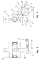
- Fig. 3 shows a schematic side view of the thrust element 15 with the Coupling element 18 and the table 4 of the embodiment.
- the clarity half of the feed finger 17 is not shown here.
- the table 4 has a guide 5 trained pins 12 for engagement with the base body 3.
- a positioning device 20 for crimp contacts 1 is assigned to the table.
- the positioning device 20 has a receiving element 27 for rods 24, on which a Guide element 21 is fastened with a screw 25.
- the bars 24 run in the receiving element 27 formed passages 28.
- a clamping screw 32 is provided for clamping the Bars 24 in the passage 28, a clamping screw 32 is provided.
- the bars 24 and the receiving element 27 together form a holding device 23.
- the table 4 has a guide area 33 for the here Feed finger 17, not shown.
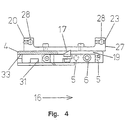
- FIG. 4 is a table 4 in a partially sectioned and schematic front view shown.
- a partially cut table 4 is the range of motion of the feed finger 17 along the table side 19 and in the guide area 33 can be seen particularly well.
- the groove 31 is for the coupling element 18 shown.
- the positioning device 20 with the holding device 23 and the Receiving element 27 shown. Passages 28 are provided for receiving rods 24 intended.
- the crimp contacts 1 are guided on a table 4 and have contact elements 22.
- the table 4 is relative movable to the base body 3, which has a pressing device 2.
- the leadership 5 for the table 4 relative to the base body 3 has an adjusting mechanism 6, with which the position of the table 4 is infinitely adjustable relative to the base body 3.
- the Guide 5 has pins 12 which are guided in receptacles 13 of the base body 3 are.
- the base body 3 is the feed unit 14 for the crimp contacts with the push element 15 assigned.
- the thrust element 15 is between two stops 35 forth. With each to and fro movement of the thrust element 15, the Band of crimp contacts 1 in the feed direction 16 to the pressing device 2 further conveyed.
- On the table 4 is a positioning device 20 with a guide element 21 arranged.
- the guide element 21 engages in the contact elements 22 of the Crimp contacts 1 on.
- the guide element 21 is via rods 24 and a receiving element 27 set on table 4.
- the feed finger 17 has a groove 31 for Engagement with the coupling element 18.
- a thread 34 for a bolt is formed in the base body 3.
- the bolt can be designed as a grub screw and is used for locking against the Screw 10 screwed.
Landscapes
- Engineering & Computer Science (AREA)
- Manufacturing & Machinery (AREA)
- Manufacturing Of Electrical Connectors (AREA)
Description
ein Crimpwerkzeug der eingangs genannten Art anzugeben, bei dem ein sicherer Langzeitbetrieb mit konstruktiv einfachen Mitteln erreicht ist.
- Fig. 1
- in sechs Vorder-, Drauf- und Seitenansichten, teilweise geschnitten und schematisch, ein Ausführungsbeispiel eines Tischs eines erfindungsgemäßen Crimpwerkzeugs,
- Fig. 2
- in einer Vorderansicht, schematisch, das Schubelement mit Koppelelement und Vorschubfinger des Ausführungsbeispiels,
- Fig. 3
- in einer Seitenansicht, schematisch, das Schubelement mit Koppelelement und Tisch des Ausführungsbeispiels,
- Fig. 4
- in einer Vorderansicht, teilweise geschnitten und schematisch, den Tisch des Ausführungsbeispiels und
- Fig. 5
- in einer Vorderansicht, schematisch, das Ausführungsbeispiel des erfindungsgemäßen Crimpwerkzeugs.
Claims (13)
- Crimpwerkzeug zum Crimpen von Crimpkontakten (1), insbesondere von Crimpkontakten (1) in Bandform, mit einem eine Preßeinrichtung (2) umfassenden Grundkörper (3) und einem dem Grundkörper (3) zugeordneten Tisch (4) zur Führung der Grimpkontakte (1), wobei die Crimpkontakte (1) der Preßeinrichtung (2) über den Tisch (4) zugeführt werden, wobei die Position des Tischs (4) relativ zum Grundkörper (3) entlang einer Führung (5) veränderbar ist, wobei ein Stellmechanismus (6) zur stufenlosen Positionierung des Tischs (4) entlang der Führung (5) vorgesehen ist und wobei der Stellmechanismus (6) ein zwischen dem Tisch (4) und dem Grundkörper (3) in Richtung der Führung (5) wirkendes elastisches Mittel (7) umfaßt, wobei das elastische Mittel (7) den Tisch (4) gegen einen dem Grundkörper (3) zugeordneten Anschlag (8) drückt dadurch gekennzeichnet, daß der Anschlag (8) eine durch den Tisch (4) geführte und in ein Gewinde in dem Grundkörper (3) geschraubte Schraube (10) ist, so daß die Verstellung der Position des Tischs (4) relativ zum Grundkörper (3) durch ein Hinein- oder Herausschrauben der Schraube (10) erfolgt.
- Crimpwerkzeug nach Anspruch 1, dadurch gekennzeichnet, daß das elastische Mittel (7) um den Anschlag (8) herum verläuft.
- Crimpwerkzeug nach Anspruch 1 oder 2, dadurch gekennzeichnet, daß das elastische Mittel (7) eine Schraubenfeder ist.
- Crimpwerkzeug nach einem der Ansprüche 1 bis 3, dadurch gekennzeichnet, daß die Schraube (10) selbstsichemd ist und/oder durch Druckbeaufschlagung gegen ein ungewolltes Herausdrehen gesichert ist.
- Crimpwerkzeug nach einem der Ansprüche 1 bis 4, dadurch gekennzeichnet, daß die Position der Schraube (10) in dem Gewinde mittels eines durch den Grundkörper (3) zur Schraube (10) hin geschraubten Bolzens gesichert ist.
- Crimpwerkzeug nach Anspruch 5, dadurch gekennzeichnet, daß der Bolzen eine Madenschraube ist.
- Crimpwerkzeug nach einem der Ansprüche 1 bis 6, dadurch gekennzeichnet, daß die Führung (5) mindestens einen und vorzugsweise zwei dem Grundkörper (3) und/oder dem Tisch (4) zugeordneten Stift (12) bzw. zugeordnete Stifte (12) umfaßt.
- Crimpwerkzeug nach Anspruch 7, dadurch gekennzeichnet, daß die Stifte (12) in in dem Tisch (4) bzw. in dem Grundkörper (3) ausgebildeten Aufnahmen (13) verlaufen.
- Crimpwerkzeug nach einem der Ansprüche 1 bis 8, dadurch gekennzeichnet, daß dem Grundkörper (3) eine Vorschubeinheit (14) für die Crimpkontakte (1) zugeordnet ist.
- Crimpwerkzeug nach Anspruch 9, dadurch gekennzeichnet, daß die Vorschubeinheit (14) ein Schubelement (15) und einen in Zuführrichtung (16) der Crimpkontakte (1) hin- und herbewegbaren Vorschubfinger (17) umfaßt, wobei der Vorschubfinger (17) mit dem Schubelement (15) über ein Koppelelement (18) wirkverbunden ist.
- Crimpwerkzeug nach Anspruch 10, dadurch gekennzeichnet, daß der Vorschubfinger (17) entlang einer Tischseite (19), vorzugsweise mittels des Tischs (4), geführt ist.
- Crimpwerkzeug nach Anspruch 10 oder 11, dadurch gekennzeichnet, daß der Abstand des Vorschubfingers (17) zum Tisch (4) während und nach der Betätigung des Stellmechanismus (6) konstant bleibt.
- Crimpwerkzeug nach einem der Ansprüche 10 bis 12, dadurch gekennzeichnet, daß das Koppeielement (18) in dem Vorschubfinger (17) derart geführt ist, daß sich der Abstand von Koppelelement (18) und Vorschubfinger (17) während der Betätigung des Stellmechanismus (6) im gleichen Maß verändert wie der Abstand von Tisch (4) und Grundkörper (3).
Applications Claiming Priority (5)
| Application Number | Priority Date | Filing Date | Title |
|---|---|---|---|
| DE19749260 | 1997-11-07 | ||
| DE19749260 | 1997-11-07 | ||
| DE19750770 | 1997-11-10 | ||
| DE1997150770 DE19750770A1 (de) | 1997-11-10 | 1997-11-10 | Crimpwerkzeug |
| PCT/DE1998/003349 WO1999025045A1 (de) | 1997-11-07 | 1998-11-09 | Crimpwerkzeug |
Publications (2)
| Publication Number | Publication Date |
|---|---|
| EP1029387A1 EP1029387A1 (de) | 2000-08-23 |
| EP1029387B1 true EP1029387B1 (de) | 2002-02-13 |
Family
ID=26041413
Family Applications (1)
| Application Number | Title | Priority Date | Filing Date |
|---|---|---|---|
| EP98965073A Expired - Lifetime EP1029387B1 (de) | 1997-11-07 | 1998-11-09 | Crimpwerkzeug |
Country Status (4)
| Country | Link |
|---|---|
| US (1) | US6298707B1 (de) |
| EP (1) | EP1029387B1 (de) |
| DE (1) | DE59803090D1 (de) |
| WO (1) | WO1999025045A1 (de) |
Cited By (2)
| Publication number | Priority date | Publication date | Assignee | Title |
|---|---|---|---|---|
| EP1764884A1 (de) | 2005-09-19 | 2007-03-21 | komax Holding AG | Crimppresse |
| US7757386B2 (en) | 2005-09-19 | 2010-07-20 | Komax Holding Ag | Crimping press |
Families Citing this family (4)
| Publication number | Priority date | Publication date | Assignee | Title |
|---|---|---|---|---|
| DE19937351A1 (de) | 1999-08-11 | 2001-03-15 | Wolfgang Hanke | Crimpwerkzeug |
| US8887380B2 (en) * | 2009-04-24 | 2014-11-18 | Tyco Electronics Corporation | Wire stop for a terminal crimping machine |
| CN111570707B (zh) * | 2020-06-09 | 2022-01-11 | 泰安市华伟重工有限责任公司 | 一种锻造操作机的夹钳装置 |
| CN114221192B (zh) * | 2021-10-20 | 2024-03-19 | 中铁十六局集团电气化工程有限公司 | 一种电力工程用压接机 |
Family Cites Families (9)
| Publication number | Priority date | Publication date | Assignee | Title |
|---|---|---|---|---|
| US4718160A (en) * | 1986-07-10 | 1988-01-12 | Panduit Corp. | Terminal strip applicator |
| US4805278A (en) * | 1986-07-10 | 1989-02-21 | Panduit Corp. | Terminal strip applicator |
| DE3937029C1 (en) * | 1989-11-07 | 1991-03-14 | Bernhard Dr.-Ing. 4782 Erwitte De Juergenhake | Crimping machine attaching contact parts to cable ends - has pivotable part with projections engaging recesses spaced along chain of contact parts |
| JP3060834B2 (ja) * | 1994-06-13 | 2000-07-10 | 住友電装株式会社 | 端子圧着装置 |
| US5577318A (en) * | 1995-07-27 | 1996-11-26 | Molex Incorporated | Electrical terminal applicator with improved track adjustment means |
| US5666719A (en) * | 1996-07-01 | 1997-09-16 | The Whitaker Corporation | Feed mechanism for a terminal applicator |
| US5799391A (en) * | 1996-09-25 | 1998-09-01 | Spring Air . . . Works, Inc. | Apparatus for significantly advancing a carrier strip and crimping various terminal configurations |
| US5887340A (en) * | 1997-08-25 | 1999-03-30 | The Whitaker Corporation | Feed position locking device for a terminal applicator |
| US6116069A (en) * | 1998-02-20 | 2000-09-12 | Icm Corporation | Axial deformation crimping machine for cable-type end connectors |
-
1998
- 1998-11-09 EP EP98965073A patent/EP1029387B1/de not_active Expired - Lifetime
- 1998-11-09 WO PCT/DE1998/003349 patent/WO1999025045A1/de not_active Ceased
- 1998-11-09 DE DE59803090T patent/DE59803090D1/de not_active Expired - Fee Related
-
2000
- 2000-05-04 US US09/564,744 patent/US6298707B1/en not_active Expired - Fee Related
Cited By (2)
| Publication number | Priority date | Publication date | Assignee | Title |
|---|---|---|---|---|
| EP1764884A1 (de) | 2005-09-19 | 2007-03-21 | komax Holding AG | Crimppresse |
| US7757386B2 (en) | 2005-09-19 | 2010-07-20 | Komax Holding Ag | Crimping press |
Also Published As
| Publication number | Publication date |
|---|---|
| DE59803090D1 (de) | 2002-03-21 |
| WO1999025045A1 (de) | 1999-05-20 |
| US6298707B1 (en) | 2001-10-09 |
| EP1029387A1 (de) | 2000-08-23 |
Similar Documents
| Publication | Publication Date | Title |
|---|---|---|
| DE8807909U1 (de) | Knochenplatte, insbesondere Kleinknochenplatte | |
| DE4010111A1 (de) | Antitotgang-mutter | |
| EP1235520A1 (de) | Vorrichtung zum distrahieren oder komprimieren von knochen oder knochenteilen | |
| EP0613757A1 (de) | Werkstück-Spannvorrichtung | |
| DE10231997A1 (de) | Einstellbares Handwerkzeug mit zwei Funktionen | |
| DE4039806C2 (de) | Schraubverbindung für mindestens zwei lösbar miteinander zu verbindende Teile, insbesondere mit Längsnuten versehene Profilstäbe | |
| DE102016014860B3 (de) | Einschraubhilfe zum Halten und Ausrichten einer Schraube | |
| DE202016007588U1 (de) | Einschraubhilfe zum Halten und Ausrichten einer Schraube | |
| DE3445885A1 (de) | Scharnier | |
| EP3683535B1 (de) | Vorrichtung zur verstellung eines schaftteils an einem gewehrschaft und gewehrschaft mit einer derartigen vorrichtung | |
| EP1029387B1 (de) | Crimpwerkzeug | |
| EP1975353A1 (de) | Beschlag zur Verriegelung von Fenstern oder Türen | |
| DE2559656A1 (de) | Anordnung mit einem einstellbaren kniehebelmechanismus, insbesondere bei zangen u.dgl. | |
| DE10212343A1 (de) | Schlittensystem | |
| DE19963818A1 (de) | Zange mit verstellbarer Maulweite für Einhandbedienung | |
| DE19750770A1 (de) | Crimpwerkzeug | |
| EP3945936B1 (de) | Einzugs oder ausstossvorrichtung | |
| DE29720287U1 (de) | Crimpwerkzeug | |
| EP0611623B1 (de) | Aufspannvorrichtung | |
| DE19924664A1 (de) | Zange mit verstellbarer Maulweite | |
| DE102004054028A1 (de) | Vorrichtung zum Positionieren einer Tür | |
| DE10151912C1 (de) | Verbinder für Profilstäbe, die eine hinterschnittene Nut aufweisen, sowie Verfahren zum Verbinden von Profilstäben | |
| DE4326642A1 (de) | Verbindungseinrichtung für Profilteile | |
| DE102019106973B3 (de) | Positioniervorrichtung für einen Anschlagskörper am Schraubstock | |
| DE4441632C2 (de) | Spanneinrichtung für Baumständer |
Legal Events
| Date | Code | Title | Description |
|---|---|---|---|
| PUAI | Public reference made under article 153(3) epc to a published international application that has entered the european phase |
Free format text: ORIGINAL CODE: 0009012 |
|
| 17P | Request for examination filed |
Effective date: 20000527 |
|
| AK | Designated contracting states |
Kind code of ref document: A1 Designated state(s): DE FR GB IT |
|
| GRAG | Despatch of communication of intention to grant |
Free format text: ORIGINAL CODE: EPIDOS AGRA |
|
| GRAG | Despatch of communication of intention to grant |
Free format text: ORIGINAL CODE: EPIDOS AGRA |
|
| GRAH | Despatch of communication of intention to grant a patent |
Free format text: ORIGINAL CODE: EPIDOS IGRA |
|
| 17Q | First examination report despatched |
Effective date: 20010426 |
|
| GRAH | Despatch of communication of intention to grant a patent |
Free format text: ORIGINAL CODE: EPIDOS IGRA |
|
| GRAA | (expected) grant |
Free format text: ORIGINAL CODE: 0009210 |
|
| REG | Reference to a national code |
Ref country code: GB Ref legal event code: IF02 |
|
| AK | Designated contracting states |
Kind code of ref document: B1 Designated state(s): DE FR GB IT |
|
| PG25 | Lapsed in a contracting state [announced via postgrant information from national office to epo] |
Ref country code: GB Free format text: LAPSE BECAUSE OF FAILURE TO SUBMIT A TRANSLATION OF THE DESCRIPTION OR TO PAY THE FEE WITHIN THE PRESCRIBED TIME-LIMIT Effective date: 20020213 |
|
| REF | Corresponds to: |
Ref document number: 59803090 Country of ref document: DE Date of ref document: 20020321 |
|
| ET | Fr: translation filed | ||
| GBV | Gb: ep patent (uk) treated as always having been void in accordance with gb section 77(7)/1977 [no translation filed] |
Effective date: 20020213 |
|
| PLBE | No opposition filed within time limit |
Free format text: ORIGINAL CODE: 0009261 |
|
| STAA | Information on the status of an ep patent application or granted ep patent |
Free format text: STATUS: NO OPPOSITION FILED WITHIN TIME LIMIT |
|
| 26N | No opposition filed |
Effective date: 20021114 |
|
| PGFP | Annual fee paid to national office [announced via postgrant information from national office to epo] |
Ref country code: FR Payment date: 20031118 Year of fee payment: 6 |
|
| PGFP | Annual fee paid to national office [announced via postgrant information from national office to epo] |
Ref country code: DE Payment date: 20040130 Year of fee payment: 6 |
|
| PG25 | Lapsed in a contracting state [announced via postgrant information from national office to epo] |
Ref country code: DE Free format text: LAPSE BECAUSE OF NON-PAYMENT OF DUE FEES Effective date: 20050601 |
|
| PG25 | Lapsed in a contracting state [announced via postgrant information from national office to epo] |
Ref country code: FR Free format text: LAPSE BECAUSE OF NON-PAYMENT OF DUE FEES Effective date: 20050729 |
|
| REG | Reference to a national code |
Ref country code: FR Ref legal event code: ST |
|
| PG25 | Lapsed in a contracting state [announced via postgrant information from national office to epo] |
Ref country code: IT Free format text: LAPSE BECAUSE OF NON-PAYMENT OF DUE FEES;WARNING: LAPSES OF ITALIAN PATENTS WITH EFFECTIVE DATE BEFORE 2007 MAY HAVE OCCURRED AT ANY TIME BEFORE 2007. THE CORRECT EFFECTIVE DATE MAY BE DIFFERENT FROM THE ONE RECORDED. Effective date: 20051109 |