EP1028541B1 - Zellulare CDMA-Funkübertragungsanordnung - Google Patents
Zellulare CDMA-Funkübertragungsanordnung Download PDFInfo
- Publication number
- EP1028541B1 EP1028541B1 EP20000108847 EP00108847A EP1028541B1 EP 1028541 B1 EP1028541 B1 EP 1028541B1 EP 20000108847 EP20000108847 EP 20000108847 EP 00108847 A EP00108847 A EP 00108847A EP 1028541 B1 EP1028541 B1 EP 1028541B1
- Authority
- EP
- European Patent Office
- Prior art keywords
- pilot
- channel
- communication channel
- base station
- radio
- Prior art date
- Legal status (The legal status is an assumption and is not a legal conclusion. Google has not performed a legal analysis and makes no representation as to the accuracy of the status listed.)
- Expired - Lifetime
Links
Images


Classifications
-
- H—ELECTRICITY
- H04—ELECTRIC COMMUNICATION TECHNIQUE
- H04J—MULTIPLEX COMMUNICATION
- H04J13/00—Code division multiplex systems
- H04J13/16—Code allocation
-
- H—ELECTRICITY
- H04—ELECTRIC COMMUNICATION TECHNIQUE
- H04W—WIRELESS COMMUNICATION NETWORKS
- H04W52/00—Power management, e.g. Transmission Power Control [TPC] or power classes
- H04W52/04—Transmission power control [TPC]
- H04W52/30—Transmission power control [TPC] using constraints in the total amount of available transmission power
- H04W52/32—TPC of broadcast or control channels
-
- H—ELECTRICITY
- H04—ELECTRIC COMMUNICATION TECHNIQUE
- H04B—TRANSMISSION
- H04B1/00—Details of transmission systems, not covered by a single one of groups H04B3/00 - H04B13/00; Details of transmission systems not characterised by the medium used for transmission
- H04B1/69—Spread spectrum techniques
- H04B1/707—Spread spectrum techniques using direct sequence modulation
-
- H—ELECTRICITY
- H04—ELECTRIC COMMUNICATION TECHNIQUE
- H04B—TRANSMISSION
- H04B7/00—Radio transmission systems, i.e. using radiation field
- H04B7/24—Radio transmission systems, i.e. using radiation field for communication between two or more posts
- H04B7/26—Radio transmission systems, i.e. using radiation field for communication between two or more posts at least one of which is mobile
- H04B7/2628—Radio transmission systems, i.e. using radiation field for communication between two or more posts at least one of which is mobile using code-division multiple access [CDMA] or spread spectrum multiple access [SSMA]
- H04B7/2637—Radio transmission systems, i.e. using radiation field for communication between two or more posts at least one of which is mobile using code-division multiple access [CDMA] or spread spectrum multiple access [SSMA] for logical channel control
-
- H—ELECTRICITY
- H04—ELECTRIC COMMUNICATION TECHNIQUE
- H04B—TRANSMISSION
- H04B1/00—Details of transmission systems, not covered by a single one of groups H04B3/00 - H04B13/00; Details of transmission systems not characterised by the medium used for transmission
- H04B1/69—Spread spectrum techniques
- H04B1/707—Spread spectrum techniques using direct sequence modulation
- H04B1/7097—Interference-related aspects
-
- H—ELECTRICITY
- H04—ELECTRIC COMMUNICATION TECHNIQUE
- H04B—TRANSMISSION
- H04B2201/00—Indexing scheme relating to details of transmission systems not covered by a single group of H04B3/00 - H04B13/00
- H04B2201/69—Orthogonal indexing scheme relating to spread spectrum techniques in general
- H04B2201/707—Orthogonal indexing scheme relating to spread spectrum techniques in general relating to direct sequence modulation
- H04B2201/70701—Orthogonal indexing scheme relating to spread spectrum techniques in general relating to direct sequence modulation featuring pilot assisted reception
Definitions
- the present invention relates to a CDMA cellular radio transmission system for use in digital cellular mobile communication and the like. Further, the invention relates to a radio base station apparatus and a radio terminal apparatus for such system and a cellular radio transmission method.
- a multiple access method means a line connection method when a plurality of stations simultaneously communicate with one another in the same band zone.
- CDMA that is, Code Division Multiple Access is a technique in which multiple access is performed by means of spectrum spread communication for transmitting an information signal spectrum by spreading the spectrum over a band sufficiently wide in comparison with the original information band width and may also be called Spectrum Spread Multiple Access (SSMA).
- SSMA Spectrum Spread Multiple Access
- a direct spread method is a method of multiplying an information signal directly by a spread sequence code in the spread process.
- a coherent detection method has excellent static characteristics in comparison with a delay detection method and is a method in which Eb/IO necessary for obtaining a certain mean bit error rate is lowest.
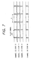
- a coherent detection scheme with interpolation has been proposed to compensate transmission signal distortion due to fading (Masaichi Sanbe "Method of Compensating for Fading Distortion of 16 QAM for Land Mobil Communication" JECS Paper B-11, Vol. J72-B-II No. 1 pp. 7-15, 1989).
- a pilot symbol 701 is, as shown in Fig. 7, inserted in an information symbol to be transmitted with each period T so as to make wave detection by estimating a channel transfer function, that is, the circuit condition.
- Fig. 4 shows the structure of a base station in a conventional CDMA cellular radio transmission system using a pilot channel.
- transmission data (2) to (m) of mobile stations m-1 (1 ⁇ m) are each spread by spread codes (2) to (m), and the spread data are then multiplied by weight before being multiplexed.
- a channel for use in transmitting the transmission data from each mobile station such as information data, control data and the like is called a "communication channel”.
- the aforementioned weight is used for transmission power control in the forward-link so as to add weight to transmission power among transmission channels.
- transmission data (1) 402 is spread by a spread code (1) 403 in a spread circuit 404, and the spread data is multiplied by weight W (1).
- the spread data in the communication channels 406 to 411 are then multiplexed in a multiplex circuit 412, and the multiplexed data is up-converted by a radio transmission unit 413 before being transmitted from an antenna 414.
- the transmission data (1) 402 since no information needs to be transmitted with the transmission data (1) 402, it may be unmodulated data (totally 0 or 1).
- Fig. 5 shows the structure of a mobile station in the conventional CDMA cellular radio transmission system using a pilot channel.
- the signal received from an antenna 501 is down-converted in a radio reception unit 502.
- a phase estimation circuit 511 detects phase information 512 from the output of a correlation circuit 505, and transfers the detected result to the detection circuit 516 of a communication channel 513.
- the pilot channel can be used as information other than coherent detection.
- reception power for each sampling (phase) is calculated in a power detection circuit 506 from the output of the correlator of the pilot channel 503, and a chip synchronous signal 508 is output by integrating (filtering) the reception power with a predetermined time constant in a chip synchronous circuit 507.
- This chip synchronous signal 508 is used to determine the phase of inverse spread with a spread code (i) 514 in the correlation circuit 515 of the communication channel 513.
- any other cell transmits pilot channels and the same spread code (1) 504 is used with shifting the phase
- the transmission power of the pilot channel required to obtain the chip synchronous signal 508 and the other-cell signal level information 510 can be lower than the power required for coherent detection, because the output of the power detection circuit is integrated in the chip synchronous circuit 507 and the other-cell monitor circuit 509.
- Unexamined Japanese Patent Publication (kokai) No. 7-76049 discloses that the base station controls the directivity of a transmission antenna on a communication channel so as to deal with the suppression of interference.
- Fig. 6 shows the situation in which the directivity is controlled.
- a base station 601 transmits signals to three mobile stations 602, 603, 604 while controlling the directivity of communication channels in the three directions of A, B, C.
- a pilot channel to be transmitted as a reference signal for coherent detection needs transmitting without directivity, because the pilot channel is commonly used for the communication channels. At this time, the propagating path of the pilot channel is different from that of the communication channel. Namely, as shown in Fig.
- paths 605, 606 refer to the situation in which the pilot channel transmitted without directivity has propagated through the path different from that of the communication channel, that is, the communication channel transmitted to have the directivity A never pass through the paths 605, 606. Therefore, the phase information of the pilot channel signal differs from that of communication channel signal.
- the weight W (1) 405 tends to become large in value (W1 > Max W2...Wm) as compared with the communication channel. If, however, W (1) is increased, the reliability of the reference signal for coherent detection is increased on one hand but since interference with communication channels (of any other station) is also increased, there arises a problem resulting in lowering communication channel quality.
- the base station controls the directivity of the transmission antenna on a communication channel basis, it is impossible to use the phase information of the pilot channel for making the coherent detection of the communication channel since the phase information obtained from the pilot channel differs from the detection phase of the communication channel.
- US-A-5 329 547 discloses a method and apparatus for encoding and decoding communication signals.
- reference symbols are inserted into a stream of input data signals to form a reference coded stream of input data symbols.
- a received communication signal is despread to derive a stream of reference samples and a stream of data samples.
- an estimated data symbol is detected from the stream of data samples by utilizing an estimated channel response determined from the stream of reference samples.
- EP-A-0 721 264 which is prior art to be considered under Article 54(3) EPC, a method and device for receiving code-division multiplex signals has been suggested.
- Each of a plurality of received spreaded signals from users is de-spreaded with a spreading code allocated to each user.
- Interference components among signal components in the de-spreaded signals are eliminated by a de-correlation filter.
- Pilot signals are detected by a pilot detection part from the interference-eliminated signals for multiple frames.
- the object of the present invention is to provide a radio transmission system, a radio base station and terminal apparatus as well as a cellular radio transmission method with an improved immunity against interference.
- the base station transmits, in addition to the pilot channel, the communication channel with the pilot symbol (known symbol) periodically inserted therein for the purpose of insert-type coherent detection, which makes unnecessary the transmission of the reference signal for coherent detection with high power so as to attain high reliability in comparison with the communication channel, whereby interference with the communication channel of any other station is reduced.
- the phase of the inverse spread code in the communication channel is obtainable by detecting the chip synchronous signal from the multiplex signal transmitted from the base station.
- the phase of the inverse spread code in the communication channel is obtainable and by detecting the other-cell signal information, the coherent detection can be made accurately from the pilot symbol inserted in the communication channel.
- Fig. 1 is a block diagram illustrating the structure of a base station in a cellular radio transmission system using a CDMA method according to Embodiment 1 of the present invention.
- reference numeral 101 denotes a pilot channel; 102, transmission data (1); 103, a spread code (1); 104, a spread circuit; 105, weight W (1); 106, a communication channel (1); 107, transmission data (2); 108, a pilot symbol (known symbol); 109, a switch; 110, a spread code (2); 111, a spread circuit; 112, weight W (2); 113, a communication channel (m-1); 114, a multi-circuit; 115, a radio transmission unit; and 116, an antenna.
- the transmission data (1) 102 is spread with the spread code (1) 103 in the spread circuit 104 and multiplied by the weight W (1) 105, and further the multiplied transmission data (1) 102 is output therefrom.
- the transmission data (1) 102 is not necessarily a piece of information to be transmitted and may be unmodulated data (data of totally 0 or 1).
- the number of communication channels is m-1.
- the communication channel (1) 106 transmits the transmission data (2) 107 on one hand, and transmits on the other hand the pilot symbol 108 which is switched via the switch 109 with each period T.
- the pilot symbol is spread with the spread code (2) 110 in the spread circuit 111 and multiplied by the weight W (2) 112 before being output.
- the same operation is performed in any other communication channel up to the communication channel (m-1).
- the outputs of the respective channels are multiplexed in the multi-circuit 114 and up-converted in the radio transmission unit 115. Then, the up-converted output is transmitted from the antenna 116.
- the pilot symbol (known symbol) for the purpose of insert-type coherent detection is periodically inserted in each communication channel. Accordingly, the interference with the communication channel of any other station can be reduced, because it is unnecessary to transmit a reference signal for coherent detection with high power in comparison with the communication channel in order to attain high reliability. Even when the communication channel is transmitted by exerting transmission antenna control, radio transmission excellent in static characteristics can be carried out since the pilot symbol inserted in the communication channel is usable for coherent detection on the mobile station side.
- the structure of a base station in the cellular radio transmission system using the CDMA method according to Embodiment 2 of the present invention is similar to the base station according to Embodiment 1 thereof.
- weight W (2) to W (m) in the communication channel are used for transmission power control, that is, for giving weight to the transmission power among the communication channels.
- the value of the weight W (1) 105 of the pilot channel is set lower than the values of weight of any other communication channel, for example, transmission with W1 ⁇ Min W2...Wm is carried out with respect to minimum values Min W2...Wm of W (2) to W (m).
- Fig. 2 is a channel format according to this embodiment of the invention.
- a pilot symbol 201 in addition to transmission data is inserted in each communication channel.
- the height of each channel indicates the transmission power thereof.
- W (2) to W (m) of the communication channels are set equal according to this embodiment, a pilot channel 203 is transmitted with low power in comparison with the communication channel.
- Fig. 2 shows a state in which a signal formed by superposing the pilot channel on the communication channels is continuously transmitted.
- the aforementioned channels can be transmitted in a multiplex mode even in a burst transmission method in which ON/OFF transmission in terms of time is effected, an intermittent transmission method or a TDD (Time Division Duplex) method in which the same radio frequency is divided for reception/transmission in terms of time.
- TDD Time Division Duplex
- the high reliability of the pilot channel as the reference signal for coherent detection is unnecessary. Since the pilot channel can be transmitted with low power in comparison with the communication channel, the interference with any other station by the pilot channel is reducible, and consequently communication channel quality can be improved.
- Fig. 3 shows a block diagram illustrating the structure of a mobile station in the cellular radio transmission system using the CDMA method according to Embodiment 3 of the invention.
- reference numeral 301 denotes an antenna; 302, a radio reception unit; 303, a pilot channel; 304, a spread code (1); 305, a correlation circuit; 306, a power detection circuit; 307, a chip synchronous circuit; 308, a chip synchronous signal; 309, an other-cell monitor circuit; 310, other-cell signal level information; 311, communication channel; 312, spread code (i); 313, a correlation circuit; 314, a detection circuit; 315, a binary value decision circuit; and 316 reception data.
- the operation of the mobile station according to this embodiment will be described.
- the signal received by the antenna 301 is down-converted in the radio reception unit 302.
- the signal is inversely spread with the spread code (1) 304 in the correlation circuit 305, and reception power is calculated on a sampling (phase) basis in the power detection circuit 306.
- the signal is subjected to integration (filtering) with a predetermined time constant in the chip synchronous circuit 307.
- the chip synchronous signal 308 is output.
- the chip synchronous signal 308 is used to determine the phase of the inverse spread with respect to the spread code (i) in the correlation circuit 313 of the communication channel 311.
- the other-cell signal level information 310 is obtainable by retrieving the reception level of a pilot channel having a different phase from the output of the power detection circuit 306 via the other-cell monitor circuit 309.
- the signal inversely spread with the spread code (i) 312 in the correlation circuit 313 is subjected to coherent detection by using the inserted pilot symbol in the detection circuit 314 and demodulated according to the decision made by the binary value decision circuit 313.
- the reception data 316 is output.
- the correlator of the communication channel is formed with a digital matched filer and a plurality of sliding correlators so as to obtain the chip synchronous information by using the output of the correlator. Further, power detection is also not always necessary to obtain the chip synchronous signal 308. Moreover, an arrangement for obtaining the other-cell signal level information 310 is unnecessary when a system is not adopted in which any other cell uses the same spread code (1) 304 and transmits the pilot channel by shifting the phase.
- the mobile station is provided with the chip synchronous circuit 307 for obtaining chip synchronization from the pilot channel, the other-cell monitor circuit 309 for obtaining the other-cell signal information and the detection circuit 314 for making coherent detection from the communication channel. Accordingly, the phase of the inverse spread code in the communication channel is obtained by detecting the chip synchronous signal and the other-cell signal information from the pilot channel transmitted with power lower than that of the communication channel from the base station. Moreover, even when the base station carries out transmissions by controlling the directivity of the transmission antenna on each communication channel, accurate coherent detection is possible from the pilot symbol inserted in the communication channel.
- the base station shown in Fig. 1 according to Embodiment 1 is combined with the mobile station shown in Fig. 3 according to Embodiment 3.
- the base station transmits, in addition to the pilot channel, the communication channel with the pilot symbol (known symbol) periodically inserted therein for the purpose of insert-type coherent detection. Accordingly, it is not necessary to transmit the reference signal for coherent detection with high power so as to attain high reliability in comparison with the communication channel. Therefore, interference with the communication channel of any other station can be reduced and the coherent detection can be made on the mobile station side by using the pilot symbol inserted in the communication channel. Even when transmission is made by controlling the directivity of the transmission antenna for each communication channel on the base station side, the phase of the inverse spread code in the communication channel is obtainable, and by detecting the other-cell signal information, the coherent detection in one's own cell can be made accurately.
- the pilot symbol known symbol
- the base station shown in Fig. 2 according to Embodiment 2 is combined with the mobile station shown in Fig. 3 according to Embodiment 3.
- the pilot channel is not necessary to obtain the high reliability as the reference signal for coherent detection. Accordingly, the base station sets the weight for making transmission power lower than that of the communication channel to thereby further reduce the interference among the base stations due to the pilot channel.
- accurate coherent detection can be effected by making the coherent detection from the communication channel with the pilot symbol inserted therein with respect to the pilot channel transmitted with power lower than that of the communication channel.
- the base station in the cellular radio transmission system using the direct spread CDMA method according to the present invention is provided with the means for outputting the pilot channel, the means for outputting the communication channel with the pilot symbol inserted therein and the means for transmitting the combination of the pilot and communication channels superposed at the same frequency. Consequently, the pilot channel need not attain high reliability as the reference signal for coherent detection and the interference with any other station by the pilot channel is reduced by transmitting the pilot channel with a lower power in comparison with the communication channel.
- the base station transmits the communication channel by controlling the antenna directivity on a communication channel basis coherent detection is made from the pilot symbol inserted in the communication channel with the effect of allowing accurate coherent detection to be made.
Landscapes
- Engineering & Computer Science (AREA)
- Computer Networks & Wireless Communication (AREA)
- Signal Processing (AREA)
- Mobile Radio Communication Systems (AREA)
- Transmitters (AREA)
Claims (9)
- Funk-Basisstationsvorrichtung, die ein Direktspreiz-CDMA-Verfahren verwendet, die umfasst:eine Einrichtung (114, 115) zum Multiplexen und Übertragen eines Steuerkanals (101) und eines Kommunikationskanals (106, 113), der ein darin eingefügtes Steuersymbol enthält, auf der gleichen Frequenz.
- Funk-Basisstationsvorrichtung, die ein Direktspreiz-CDMA-Verfahren verwendet, nach Anspruch 1, die eine Steuereinrichtung für die Richtwirkung einer Sendeantenne für wenigstens einen Kanal umfasst.
- Funk-Endgerätvorrichtung, die ein Direktspreiz-CDMA-Verfahren verwendet und die geeignet ist, das von der Funk-Basisstationsvorrichtung nach Anspruch 1 oder 2 übertragene Signal zu empfangen.
- Funk-Endgerätvorrichtung, die ein Direktspreiz-CDMA-Verfahren verwendet, nach Anspruch 3, die des Weiteren umfasst:eine Einrichtung (307) zum Erhalten einer Chip-Synchronisierung aus dem von der Funk-Basisstationsvorrichtung übertragenen Signal; undeine Einrichtung (314) zum Herstellen einer kohärenten Erfassung unter Verwendung des Steuersignals (108) in dem Steuer- oder dem Kommunikationskanal (101, 106, 113).
- Funk-Übertragungssystem, das ein Direktspreiz-CDMA-Verfahren verwendet, das eine Funk-Basisstationsvorrichtung und eine Funk-Endgerätvorrichtung umfasst, wobei die Funk-Basisstation eine Einrichtung (114, 115) zum Multiplexen und Übertragen eines Steuerkanals und eines Kommunikationskanals, der ein darin eingefügtes Steuersymbol enthält, auf der gleichen Frequenz umfasst; und
die Funk-Endgerätvorrichtung eine Einrichtung (307) zum Erhalten einer Chip-Synchronisierung aus dem von der Funk-Basisstation übertragenen Signal umfasst; und
eine Einrichtung zum Herstellen einer kohärenten Erfassung unter Verwendung des Steuersignals in dem Steuer- oder dem Kommunikationskanal. - Funk-Übertragungssystem, das ein Direktspreiz-CDMA-Verfahren verwendet, nach Anspruch 5, wobei die Funk-Basisstation eine Steuereinrichtung für die Richtwirkung einer Sendeantenne für wenigstens einen Kanal umfasst.
- Zellulares Funk-Übertragungsverfahren, das ein Direktspreiz-CDMA-Verfahren verwendet, das den folgenden Schritt umfasst:Multiplexen und Übertragen eines Steuerkanals und eines Kommunikationskanals, der ein darin eingefügtes Steuersymbol enthält, auf der gleichen Frequenz durch eine Funk-Basisstation.
- Zellulares Funk-Übertragungsverfahren nach Anspruch 7, das des Weiteren die folgenden Schritte umfasst:Erhalten einer Chip-Synchronisierung aus dem von der Funk-Basisstation übertragenen Signal durch eine Funk-Endgerätvorrichtung; undHerstellen einer kohärenten Erfassung unter Verwendung des Steuersignals in dem Kommunikationskanal durch die Funk-Endgerätvorrichtung.
- Zellulares Funk-Übertragungsverfahren nach Anspruch 8, wobei wenigstens ein Kanal von der Funk-Basisstationsvorrichtung unter Steuerung der Richtwirkung einer Sendeantenne übertragen wird.
Applications Claiming Priority (3)
| Application Number | Priority Date | Filing Date | Title |
|---|---|---|---|
| JP5971196 | 1996-03-15 | ||
| JP5971196A JP2934185B2 (ja) | 1996-03-15 | 1996-03-15 | Cdmaセルラ無線基地局装置および移動局装置および送信方法 |
| EP19970104408 EP0795969B1 (de) | 1996-03-15 | 1997-03-14 | Zellulare CDMA-Funkübertragungsanordnung |
Related Parent Applications (1)
| Application Number | Title | Priority Date | Filing Date |
|---|---|---|---|
| EP19970104408 Division EP0795969B1 (de) | 1996-03-15 | 1997-03-14 | Zellulare CDMA-Funkübertragungsanordnung |
Publications (3)
| Publication Number | Publication Date |
|---|---|
| EP1028541A2 EP1028541A2 (de) | 2000-08-16 |
| EP1028541A3 EP1028541A3 (de) | 2000-12-06 |
| EP1028541B1 true EP1028541B1 (de) | 2002-08-14 |
Family
ID=13121073
Family Applications (2)
| Application Number | Title | Priority Date | Filing Date |
|---|---|---|---|
| EP20000108847 Expired - Lifetime EP1028541B1 (de) | 1996-03-15 | 1997-03-14 | Zellulare CDMA-Funkübertragungsanordnung |
| EP19970104408 Expired - Lifetime EP0795969B1 (de) | 1996-03-15 | 1997-03-14 | Zellulare CDMA-Funkübertragungsanordnung |
Family Applications After (1)
| Application Number | Title | Priority Date | Filing Date |
|---|---|---|---|
| EP19970104408 Expired - Lifetime EP0795969B1 (de) | 1996-03-15 | 1997-03-14 | Zellulare CDMA-Funkübertragungsanordnung |
Country Status (6)
| Country | Link |
|---|---|
| US (4) | US6028852A (de) |
| EP (2) | EP1028541B1 (de) |
| JP (1) | JP2934185B2 (de) |
| KR (1) | KR100422845B1 (de) |
| CN (1) | CN1096201C (de) |
| DE (2) | DE69702875T2 (de) |
Families Citing this family (62)
| Publication number | Priority date | Publication date | Assignee | Title |
|---|---|---|---|---|
| JP3200547B2 (ja) * | 1995-09-11 | 2001-08-20 | 株式会社日立製作所 | Cdma方式移動通信システム |
| JP2934185B2 (ja) * | 1996-03-15 | 1999-08-16 | 松下電器産業株式会社 | Cdmaセルラ無線基地局装置および移動局装置および送信方法 |
| DE69840527D1 (de) * | 1997-04-17 | 2009-03-19 | Ntt Docomo Inc | Sendegerät für ein Mobilfunksystem |
| US9118387B2 (en) * | 1997-11-03 | 2015-08-25 | Qualcomm Incorporated | Pilot reference transmission for a wireless communication system |
| US7184426B2 (en) * | 2002-12-12 | 2007-02-27 | Qualcomm, Incorporated | Method and apparatus for burst pilot for a time division multiplex system |
| CN1134126C (zh) * | 1997-12-10 | 2004-01-07 | 三菱电机株式会社 | 移动通信系统 |
| JP3266091B2 (ja) * | 1998-03-04 | 2002-03-18 | 日本電気株式会社 | セルラシステム |
| GB2335828B (en) * | 1998-03-04 | 2003-08-20 | Internat Mobile Satellite Orga | Satellite Communications System |
| US6744754B1 (en) * | 1998-06-09 | 2004-06-01 | Lg Information & Communications, Ltd. | Control of forward link power CDMA mobile communication system |
| CN1068745C (zh) * | 1998-07-17 | 2001-07-18 | 中国人民解放军信息工程学院 | 实现共用时分导频同步正交码分多址信道的方法 |
| KR100306286B1 (ko) * | 1998-08-04 | 2001-09-29 | 윤종용 | 부호분할 다중접속 통신시스템의 채널 통신 장치 및 방법 |
| JP3029030B2 (ja) * | 1998-08-05 | 2000-04-04 | 日本電気株式会社 | パイロット信号を含む受信信号の復調方法およびその装置 |
| US6393010B1 (en) * | 1998-08-19 | 2002-05-21 | Qualcomm Incorporated | Time offset technique for increasing the capacity of a CDMA system |
| US6396817B2 (en) | 1998-08-31 | 2002-05-28 | Qualcomm Incorporated | Signal splitting method for limiting peak power in a CDMA system |
| KR100401211B1 (ko) * | 1998-09-03 | 2004-03-30 | 삼성전자주식회사 | 부호분할다중접속통신시스템에서역방향파일럿신호의통신장치및방법 |
| US6411649B1 (en) * | 1998-10-20 | 2002-06-25 | Ericsson Inc. | Adaptive channel tracking using pilot sequences |
| JP2000151557A (ja) | 1998-11-13 | 2000-05-30 | Nec Corp | Cdma通信装置 |
| JP3380481B2 (ja) * | 1998-12-17 | 2003-02-24 | 松下電器産業株式会社 | 基地局装置 |
| US7406098B2 (en) * | 1999-01-13 | 2008-07-29 | Qualcomm Incorporated | Resource allocation in a communication system supporting application flows having quality of service requirements |
| US6393012B1 (en) * | 1999-01-13 | 2002-05-21 | Qualcomm Inc. | System for allocating resources in a communication system |
| JP3410379B2 (ja) * | 1999-02-26 | 2003-05-26 | 松下電器産業株式会社 | 無線通信基地局装置及び無線通信方法 |
| EP1039657A1 (de) * | 1999-03-19 | 2000-09-27 | Alcatel | Verfahren zur Pilotsignalsleistungsregelung in einem CDMA Mobilfunksystem und Basisstation und Mobilstation für ein solches System |
| EP1069696B1 (de) * | 1999-06-24 | 2006-09-27 | Alcatel | Empfänger und Verfahren mit verbesserter Leistung für CDMA Übertragung |
| EP1065800A1 (de) * | 1999-07-02 | 2001-01-03 | Lucent Technologies Inc. | CDMA-System mit verbesserten Pilot-Kanälen |
| US6996080B1 (en) * | 1999-07-23 | 2006-02-07 | Itt Manufacturing Enterprises, Inc. | Chip-synchronous CDMA multiplexer and method resulting in constant envelope signals |
| US6633552B1 (en) * | 1999-08-06 | 2003-10-14 | Qualcomm Incorporated | Method and apparatus for determining the closed loop power control set point in a wireless packet data communication system |
| US6680987B1 (en) * | 1999-08-10 | 2004-01-20 | Hughes Electronics Corporation | Fading communications channel estimation and compensation |
| US8064409B1 (en) | 1999-08-25 | 2011-11-22 | Qualcomm Incorporated | Method and apparatus using a multi-carrier forward link in a wireless communication system |
| US6115406A (en) * | 1999-09-10 | 2000-09-05 | Interdigital Technology Corporation | Transmission using an antenna array in a CDMA communication system |
| US6621804B1 (en) * | 1999-10-07 | 2003-09-16 | Qualcomm Incorporated | Method and apparatus for predicting favored supplemental channel transmission slots using transmission power measurements of a fundamental channel |
| JP3793380B2 (ja) | 1999-10-22 | 2006-07-05 | 株式会社エヌ・ティ・ティ・ドコモ | Cdma移動通信システムにおける下りリンクのパイロットチャネルの送信方法およびcdma移動通信システム |
| US6665288B1 (en) * | 1999-11-08 | 2003-12-16 | Ericsson Inc. | Method and apparatus for reducing synchronization code interference in CDMA communications systems |
| JP3522619B2 (ja) | 2000-01-05 | 2004-04-26 | 株式会社エヌ・ティ・ティ・ドコモ | マルチキャリアcdma伝送システムにおける送信機 |
| KR100459564B1 (ko) * | 2000-06-21 | 2004-12-03 | 삼성전자주식회사 | 이동통신시스템에서 서비스 부하를 단말기에 보고하기위한 장치 및 방법 |
| US6411608B2 (en) | 2000-07-12 | 2002-06-25 | Symbol Technologies, Inc. | Method and apparatus for variable power control in wireless communications systems |
| US6765974B1 (en) | 2000-07-19 | 2004-07-20 | Radwin Ltd. | Rach starting time vicinity estimation |
| EP1653756A1 (de) * | 2000-10-19 | 2006-05-03 | NTT DoCoMo, Inc. | Übertragungsverfahren eines Abwärtspilotkanals in einem CDMA-Mobilkommunikationssystem, und CDMA-Kommunikationssystem |
| US7068683B1 (en) | 2000-10-25 | 2006-06-27 | Qualcomm, Incorporated | Method and apparatus for high rate packet data and low delay data transmissions |
| US6973098B1 (en) * | 2000-10-25 | 2005-12-06 | Qualcomm, Incorporated | Method and apparatus for determining a data rate in a high rate packet data wireless communications system |
| JP3506330B2 (ja) * | 2000-12-27 | 2004-03-15 | 松下電器産業株式会社 | データ送信装置 |
| JP2004289191A (ja) * | 2001-01-19 | 2004-10-14 | Yozan Inc | Ds−cdmaシステムにおけるパスサーチ方法および受信装置 |
| JP5079189B2 (ja) | 2001-04-13 | 2012-11-21 | Kddi株式会社 | 多ビームセルラ無線基地局、移動機及びスペクトラム拡散信号送信方法 |
| CN101626616B (zh) * | 2001-06-13 | 2015-05-20 | 英特尔公司 | 以低于心跳请求的能级进行心跳信号传输 |
| IL159361A0 (en) * | 2001-06-26 | 2004-06-01 | Qualcomm Inc | Method and apparatus for adaptive server selection in a data communication system |
| US6757520B2 (en) * | 2001-06-26 | 2004-06-29 | Qualcomm Incorporated | Method and apparatus for selecting a serving sector in a data communication system |
| JP4448633B2 (ja) * | 2001-08-31 | 2010-04-14 | 富士通株式会社 | 移動体通信端末 |
| US7453801B2 (en) * | 2001-11-08 | 2008-11-18 | Qualcomm Incorporated | Admission control and resource allocation in a communication system supporting application flows having quality of service requirements |
| US20030179737A1 (en) * | 2002-03-25 | 2003-09-25 | Avner Dor | Processing non-pilot channels in a CDMA searcher |
| JP4165238B2 (ja) * | 2003-01-29 | 2008-10-15 | 日本電気株式会社 | パスサーチ回路及びその方法ならびにプログラム |
| US7385617B2 (en) | 2003-05-07 | 2008-06-10 | Illinois Institute Of Technology | Methods for multi-user broadband wireless channel estimation |
| JP3799030B2 (ja) * | 2003-05-09 | 2006-07-19 | 松下電器産業株式会社 | Cdma送信装置およびcdma送信方法 |
| DE602004012069T2 (de) * | 2004-05-03 | 2009-02-26 | Alcatel Lucent | Übertragungsmodusselektion mittels Qualitätsschätzung eines zusammengesetzten Signals |
| US7894402B2 (en) * | 2005-04-15 | 2011-02-22 | Alcatel-Lucent Usa Inc. | High rate packet data spatial division multiple access (SDMA) |
| US8339930B2 (en) * | 2005-05-16 | 2012-12-25 | Qualcomm Incorporated | Pilot transmission and channel estimation with pilot weighting |
| US8243850B2 (en) * | 2006-10-24 | 2012-08-14 | Samsung Electronics Co., Ltd. | Method and system for generating reference signals in a wireless communication system |
| US8019451B2 (en) * | 2006-11-22 | 2011-09-13 | Target Brands, Inc. | Financial transaction product with media player |
| CN101247185B (zh) * | 2008-03-05 | 2011-06-22 | 中兴通讯股份有限公司 | 一种用于检测信号高低功率变化的装置及方法 |
| US8149929B2 (en) * | 2008-06-17 | 2012-04-03 | Telefonaktiebolaget L M Ericsson (Publ) | Receiver and method for processing radio signals using soft pilot symbols |
| US8391253B2 (en) * | 2008-11-20 | 2013-03-05 | Telefonaktiebolaget L M Ericsson (Publ) | Time-division multiplexed pilot signal for integrated mobile broadcasts |
| GB2474794B (en) | 2008-11-27 | 2011-06-15 | Ipwireless Inc | Communication system, communication units, and method for employing a pilot transmission scheme |
| US8811200B2 (en) * | 2009-09-22 | 2014-08-19 | Qualcomm Incorporated | Physical layer metrics to support adaptive station-dependent channel state information feedback rate in multi-user communication systems |
| KR20160075995A (ko) * | 2014-12-19 | 2016-06-30 | 한국전자통신연구원 | 물리 채널 전송 방법 및 장치 |
Family Cites Families (21)
| Publication number | Priority date | Publication date | Assignee | Title |
|---|---|---|---|---|
| JP2959579B2 (ja) | 1990-06-19 | 1999-10-06 | キヤノン株式会社 | X線露光装置 |
| US5103459B1 (en) * | 1990-06-25 | 1999-07-06 | Qualcomm Inc | System and method for generating signal waveforms in a cdma cellular telephone system |
| US5170413A (en) * | 1990-12-24 | 1992-12-08 | Motorola, Inc. | Control strategy for reuse system assignments and handoff |
| US5329547A (en) * | 1993-03-11 | 1994-07-12 | Motorola, Inc. | Method and apparatus for coherent communication in a spread-spectrum communication system |
| JPH0776049A (ja) * | 1993-06-25 | 1995-03-20 | Rojiyaasu Inoatsuku:Kk | スポンジローラの製造方法及びその方法により製造される電子機器用スポンジローラ |
| MY112371A (en) * | 1993-07-20 | 2001-05-31 | Qualcomm Inc | System and method for orthogonal spread spectrum sequence generation in variable data rate systems |
| JP2576388B2 (ja) * | 1993-11-08 | 1997-01-29 | 日本電気株式会社 | 基地局送受信装置 |
| JP3158821B2 (ja) * | 1993-12-14 | 2001-04-23 | 株式会社日立製作所 | Cdma移動通信システムおよび装置 |
| FI941072A7 (fi) * | 1994-03-07 | 1995-09-08 | Nokia Mobile Phones Ltd | Tiedonsiirtomenetelmä, lähetin sekä vastaanotin |
| US5544156A (en) * | 1994-04-29 | 1996-08-06 | Telefonaktiebolaget Lm Ericsson | Direct sequence CDMA coherent uplink detector |
| JP3118548B2 (ja) * | 1994-06-22 | 2000-12-18 | 株式会社エヌ・ティ・ティ・ドコモ | ディジタル通信受信機用同期検波装置および同期方法 |
| EP0716520B1 (de) * | 1994-06-23 | 2004-05-12 | NTT DoCoMo, Inc. | Cdma demodulationsschaltung und -verfahren |
| EP0721264B1 (de) * | 1994-06-23 | 2003-11-26 | Ntt Mobile Communications Network Inc. | Verfahren und anordnung zum empfangen eines code-division-multiplexsignals |
| CA2153617A1 (en) * | 1994-07-14 | 1996-01-15 | Takayuki Nakano | Cdma receiving apparatus |
| CA2153516C (en) * | 1994-07-20 | 1999-06-01 | Yasuo Ohgoshi | Mobile station for cdma mobile communication system and detection method of the same |
| US5822359A (en) * | 1994-10-17 | 1998-10-13 | Motorola, Inc. | Coherent random access channel in a spread-spectrum communication system and method |
| CA2197342C (en) * | 1995-06-13 | 2001-11-06 | Mamoru Sawahashi | Cdma demodulating apparatus |
| US5809061A (en) * | 1995-08-14 | 1998-09-15 | Sigtek, Inc. | CDMA communication system with pilot tone control |
| US5719898A (en) * | 1995-09-29 | 1998-02-17 | Golden Bridge Technology, Inc. | Fuzzy-logic spread-spectrum adaptive power control |
| US5850393A (en) * | 1995-11-09 | 1998-12-15 | Ntt Mobile Communications Network, Inc. | Transmitter receiver for mobile communication system |
| JP2934185B2 (ja) * | 1996-03-15 | 1999-08-16 | 松下電器産業株式会社 | Cdmaセルラ無線基地局装置および移動局装置および送信方法 |
-
1996
- 1996-03-15 JP JP5971196A patent/JP2934185B2/ja not_active Expired - Lifetime
-
1997
- 1997-03-13 US US08/815,621 patent/US6028852A/en not_active Expired - Lifetime
- 1997-03-14 DE DE69702875T patent/DE69702875T2/de not_active Expired - Lifetime
- 1997-03-14 EP EP20000108847 patent/EP1028541B1/de not_active Expired - Lifetime
- 1997-03-14 DE DE69714792T patent/DE69714792T2/de not_active Expired - Lifetime
- 1997-03-14 EP EP19970104408 patent/EP0795969B1/de not_active Expired - Lifetime
- 1997-03-15 KR KR1019970008880A patent/KR100422845B1/ko not_active Expired - Lifetime
- 1997-03-15 CN CN97109576A patent/CN1096201C/zh not_active Expired - Lifetime
-
1999
- 1999-12-09 US US09/457,785 patent/US6400700B1/en not_active Expired - Lifetime
-
2000
- 2000-07-12 US US09/615,325 patent/US6493330B1/en not_active Expired - Lifetime
- 2000-10-02 US US09/676,507 patent/US6480479B1/en not_active Expired - Lifetime
Also Published As
| Publication number | Publication date |
|---|---|
| EP0795969A2 (de) | 1997-09-17 |
| DE69702875D1 (de) | 2000-09-28 |
| KR970068214A (ko) | 1997-10-13 |
| DE69714792T2 (de) | 2002-12-05 |
| EP0795969B1 (de) | 2000-08-23 |
| JPH09252266A (ja) | 1997-09-22 |
| EP1028541A2 (de) | 2000-08-16 |
| JP2934185B2 (ja) | 1999-08-16 |
| CN1165460A (zh) | 1997-11-19 |
| US6493330B1 (en) | 2002-12-10 |
| US6028852A (en) | 2000-02-22 |
| US6480479B1 (en) | 2002-11-12 |
| EP1028541A3 (de) | 2000-12-06 |
| CN1096201C (zh) | 2002-12-11 |
| KR100422845B1 (ko) | 2004-07-12 |
| EP0795969A3 (de) | 1998-12-23 |
| DE69714792D1 (de) | 2002-09-19 |
| US6400700B1 (en) | 2002-06-04 |
| DE69702875T2 (de) | 2000-12-07 |
Similar Documents
| Publication | Publication Date | Title |
|---|---|---|
| EP1028541B1 (de) | Zellulare CDMA-Funkübertragungsanordnung | |
| JP2863993B2 (ja) | Cdma無線多重送信装置およびcdma無線多重伝送装置およびcdma無線受信装置およびcdma無線多重送信方法 | |
| JP3408545B2 (ja) | スペクトラム拡散通信システムにおける移動局の同期 | |
| EP0798872B1 (de) | Mobiles CDMA-Nachrichtenübertragungssystem | |
| US6351458B2 (en) | CDMA cellular wireless communication system | |
| EP0668668A1 (de) | CDMA/TDD mobile Kommunikationsanordnung mit Wahl der Übertragungsantennen | |
| EP0794627B1 (de) | Spreizspektrumübertragungsgerät | |
| KR100355327B1 (ko) | 통신 단말 장치 및 그와 통신하는 기지국 장치와 무선 통신 방법 | |
| US6370131B1 (en) | CDMA radio multiplex transmitting device and a CDMA radio multiplex receiving device | |
| EP0964529A2 (de) | Einrichtung zur Kanalschätzung und Übertragungsendgerät | |
| US6047015A (en) | Mobile radio apparatus | |
| JP3411150B2 (ja) | Cdmaセルラ無線通信装置 | |
| US7280583B1 (en) | Method of transmitting data signals between a master station and a plurality of slave stations, master station and slave station | |
| EP1176730A1 (de) | Störungsschätzung in einem Kommunikationssystem | |
| JPH08168075A (ja) | 移動無線装置 | |
| JP3150312B2 (ja) | Cdmaセルラ無線基地局装置及び移動局装置及び送信方法及び受信方法 | |
| KR100304670B1 (ko) | 파일럿 및 트래픽 채널을 이용한 채널 추정기, 그 방법 그리고 이를 구비한 직접 시퀀스 코드분할다중접속 수신기 | |
| JPH10126313A (ja) | Cdma移動体通信装置 | |
| JP3203322B2 (ja) | Cdma基地局装置 | |
| JPH10262028A (ja) | Cdma無線多重送信装置およびcdma無線多重伝送装置およびcdma無線多重送信方法 | |
| CN1148452A (zh) | 使用多个天线进行信号捕获和信道估算的方法和设备 | |
| KR100319751B1 (ko) | 공간-시간 다이버시티 수신기용 채널 예측장치 및 그 방법 | |
| JP3353551B2 (ja) | 符号多重受信装置 | |
| JPH11341553A (ja) | スペクトラム拡散通信方式 | |
| JPH06164546A (ja) | 移動通信システム |
Legal Events
| Date | Code | Title | Description |
|---|---|---|---|
| PUAI | Public reference made under article 153(3) epc to a published international application that has entered the european phase |
Free format text: ORIGINAL CODE: 0009012 |
|
| AC | Divisional application: reference to earlier application |
Ref document number: 795969 Country of ref document: EP |
|
| AK | Designated contracting states |
Kind code of ref document: A2 Designated state(s): DE FI FR GB SE |
|
| AX | Request for extension of the european patent |
Free format text: AL;LT;LV;RO;SI |
|
| PUAL | Search report despatched |
Free format text: ORIGINAL CODE: 0009013 |
|
| RIN1 | Information on inventor provided before grant (corrected) |
Inventor name: WATANABE, MASATOSHI Inventor name: KATO, OSAMU Inventor name: MIYA, KAZUYUKI |
|
| AK | Designated contracting states |
Kind code of ref document: A3 Designated state(s): AT BE CH DE DK ES FI FR GB GR IE IT LI LU MC NL PT SE |
|
| AX | Request for extension of the european patent |
Free format text: AL;LT;LV;RO;SI |
|
| RIN1 | Information on inventor provided before grant (corrected) |
Inventor name: KATO, OSAMU Inventor name: MIYA, KAZUYUKI Inventor name: WATANABE, MASATOSHI |
|
| 17P | Request for examination filed |
Effective date: 20010122 |
|
| 17Q | First examination report despatched |
Effective date: 20010405 |
|
| AKX | Designation fees paid |
Free format text: DE FI FR GB SE |
|
| GRAG | Despatch of communication of intention to grant |
Free format text: ORIGINAL CODE: EPIDOS AGRA |
|
| GRAG | Despatch of communication of intention to grant |
Free format text: ORIGINAL CODE: EPIDOS AGRA |
|
| GRAH | Despatch of communication of intention to grant a patent |
Free format text: ORIGINAL CODE: EPIDOS IGRA |
|
| GRAH | Despatch of communication of intention to grant a patent |
Free format text: ORIGINAL CODE: EPIDOS IGRA |
|
| GRAA | (expected) grant |
Free format text: ORIGINAL CODE: 0009210 |
|
| AC | Divisional application: reference to earlier application |
Ref document number: 795969 Country of ref document: EP |
|
| AK | Designated contracting states |
Kind code of ref document: B1 Designated state(s): DE FI FR GB SE |
|
| REG | Reference to a national code |
Ref country code: GB Ref legal event code: FG4D |
|
| RIN1 | Information on inventor provided before grant (corrected) |
Inventor name: KATO, OSAMU Inventor name: WATANABE, MASATOSHI Inventor name: MIYA, KAZUYUKI |
|
| REF | Corresponds to: |
Ref document number: 69714792 Country of ref document: DE Date of ref document: 20020919 |
|
| ET | Fr: translation filed | ||
| PLBE | No opposition filed within time limit |
Free format text: ORIGINAL CODE: 0009261 |
|
| STAA | Information on the status of an ep patent application or granted ep patent |
Free format text: STATUS: NO OPPOSITION FILED WITHIN TIME LIMIT |
|
| 26N | No opposition filed |
Effective date: 20030515 |
|
| REG | Reference to a national code |
Ref country code: GB Ref legal event code: 732E Free format text: REGISTERED BETWEEN 20140612 AND 20140618 |
|
| REG | Reference to a national code |
Ref country code: DE Ref legal event code: R082 Ref document number: 69714792 Country of ref document: DE Representative=s name: GRUENECKER, KINKELDEY, STOCKMAIR & SCHWANHAEUS, DE |
|
| REG | Reference to a national code |
Ref country code: DE Ref legal event code: R081 Ref document number: 69714792 Country of ref document: DE Owner name: PANASONIC INTELLECTUAL PROPERTY CORPORATION OF, US Free format text: FORMER OWNER: PANASONIC CORPORATION, KADOMA-SHI, OSAKA, JP Effective date: 20140711 Ref country code: DE Ref legal event code: R082 Ref document number: 69714792 Country of ref document: DE Representative=s name: GRUENECKER, KINKELDEY, STOCKMAIR & SCHWANHAEUS, DE Effective date: 20140711 Ref country code: DE Ref legal event code: R082 Ref document number: 69714792 Country of ref document: DE Representative=s name: GRUENECKER PATENT- UND RECHTSANWAELTE PARTG MB, DE Effective date: 20140711 |
|
| REG | Reference to a national code |
Ref country code: FR Ref legal event code: TP Owner name: PANASONIC INTELLECTUAL PROPERTY CORPORATION OF, US Effective date: 20140722 |
|
| REG | Reference to a national code |
Ref country code: FR Ref legal event code: PLFP Year of fee payment: 20 |
|
| PGFP | Annual fee paid to national office [announced via postgrant information from national office to epo] |
Ref country code: DE Payment date: 20160308 Year of fee payment: 20 |
|
| PGFP | Annual fee paid to national office [announced via postgrant information from national office to epo] |
Ref country code: GB Payment date: 20160309 Year of fee payment: 20 Ref country code: SE Payment date: 20160311 Year of fee payment: 20 Ref country code: FR Payment date: 20160208 Year of fee payment: 20 Ref country code: FI Payment date: 20160309 Year of fee payment: 20 |
|
| REG | Reference to a national code |
Ref country code: DE Ref legal event code: R071 Ref document number: 69714792 Country of ref document: DE |
|
| REG | Reference to a national code |
Ref country code: GB Ref legal event code: PE20 Expiry date: 20170313 |
|
| REG | Reference to a national code |
Ref country code: SE Ref legal event code: EUG |
|
| PG25 | Lapsed in a contracting state [announced via postgrant information from national office to epo] |
Ref country code: GB Free format text: LAPSE BECAUSE OF EXPIRATION OF PROTECTION Effective date: 20170313 |