EP1069696B1 - Empfänger und Verfahren mit verbesserter Leistung für CDMA Übertragung - Google Patents
Empfänger und Verfahren mit verbesserter Leistung für CDMA Übertragung Download PDFInfo
- Publication number
- EP1069696B1 EP1069696B1 EP99440158A EP99440158A EP1069696B1 EP 1069696 B1 EP1069696 B1 EP 1069696B1 EP 99440158 A EP99440158 A EP 99440158A EP 99440158 A EP99440158 A EP 99440158A EP 1069696 B1 EP1069696 B1 EP 1069696B1
- Authority
- EP
- European Patent Office
- Prior art keywords
- receiver
- path
- channels
- channel
- paths
- Prior art date
- Legal status (The legal status is an assumption and is not a legal conclusion. Google has not performed a legal analysis and makes no representation as to the accuracy of the status listed.)
- Expired - Lifetime
Links
- 230000005540 biological transmission Effects 0.000 title claims description 6
- 238000000034 method Methods 0.000 title description 4
- 238000012935 Averaging Methods 0.000 claims description 11
- 230000001934 delay Effects 0.000 claims description 9
- 238000000605 extraction Methods 0.000 claims 1
- 238000001228 spectrum Methods 0.000 description 3
- 108010003272 Hyaluronate lyase Proteins 0.000 description 2
- 239000000523 sample Substances 0.000 description 2
- 230000007480 spreading Effects 0.000 description 2
- 230000008901 benefit Effects 0.000 description 1
- 230000000295 complement effect Effects 0.000 description 1
- 230000003111 delayed effect Effects 0.000 description 1
- 238000001514 detection method Methods 0.000 description 1
- 238000010586 diagram Methods 0.000 description 1
- PCHJSUWPFVWCPO-UHFFFAOYSA-N gold Chemical compound [Au] PCHJSUWPFVWCPO-UHFFFAOYSA-N 0.000 description 1
- 239000010931 gold Substances 0.000 description 1
- 229910052737 gold Inorganic materials 0.000 description 1
- 230000008569 process Effects 0.000 description 1
- 230000004044 response Effects 0.000 description 1
Images


Classifications
-
- H—ELECTRICITY
- H04—ELECTRIC COMMUNICATION TECHNIQUE
- H04B—TRANSMISSION
- H04B1/00—Details of transmission systems, not covered by a single one of groups H04B3/00 - H04B13/00; Details of transmission systems not characterised by the medium used for transmission
- H04B1/69—Spread spectrum techniques
- H04B1/707—Spread spectrum techniques using direct sequence modulation
- H04B1/7097—Interference-related aspects
- H04B1/711—Interference-related aspects the interference being multi-path interference
- H04B1/7113—Determination of path profile
-
- H—ELECTRICITY
- H04—ELECTRIC COMMUNICATION TECHNIQUE
- H04B—TRANSMISSION
- H04B1/00—Details of transmission systems, not covered by a single one of groups H04B3/00 - H04B13/00; Details of transmission systems not characterised by the medium used for transmission
- H04B1/69—Spread spectrum techniques
- H04B1/707—Spread spectrum techniques using direct sequence modulation
- H04B1/7097—Interference-related aspects
- H04B1/711—Interference-related aspects the interference being multi-path interference
- H04B1/7115—Constructive combining of multi-path signals, i.e. RAKE receivers
- H04B1/712—Weighting of fingers for combining, e.g. amplitude control or phase rotation using an inner loop
Definitions
- the invention relates to a receiver for enhanced performance for CDMA transmission as described in the subject of the independent claims.
- the transmitted signal is reflected and refracted by a variety of smooth or rough terrains, so that it is replicated at the receiver with several time delays.
- Each individual path also arrives at is own amplitude and carrier phase.
- Propagation characteristics are qualitatively the same for all structures of signals though they will vary quantitatively with carrier frequency and terrain characteristics.
- the structures of the individual propagation paths can be identified and possibly exploited only on the extent that they can be distinguished from one other.
- spread spectrum signals employ pseudo random sequences with chip time Tc inversely proportional to the spreading bandwidth. In this case the individual paths can be distinguished if they mutually separated by delays greater than Tc for then the various delayed versions of the signal will be mutually uncorrelated.
- Fig. 1 The situation is shown in Fig. 1.
- the path amplitudes ⁇ will depend on the relative propagation distances and the reflective or refractive properties of the area. However in many cases particularly in confined areas each of the distinguishable multipath components will actually be itself the linear combination of several indistinguishable paths of varying amplitudes. To exploit energy in the multiple components of multipath propagation they must be identifies and acquired. It is particularly important to determine the relative delays and subsequently when possible their amplitudes and phases. This can be performed even with fully modulated signals, but the estimate is much precise and resulting performance is much improved if the path identification and parameter estimation is performed on an unmodulated signal. Unmodulated segments can be inserted every so often in the modulated signal particularly with time division multiplexing. However in spread spectrum systems it is much more effective and easier to separate the unmodulated pilot signals from the data modulated signal by assigning it an individual pseudo random sequence.
- a pilot sequence for determining multipath component characteristics is well justified for one-to-many transmission channels such as the forward down link from a base station to multiple users.
- the optimum demodulator structure for a L multipath propagation channel is known as Rake receiver.
- Each mulipath component demodulator is called a "finger" of the rake.
- the pilot sequence tracking of a particular demodulator is started by time delay estimation of a given path as determined by the pilots sequences searcher.
- the demodulator forms the weighted phase-adjusted and delay-adjusted sum of L components.
- the profile of the powers of each of the L paths is taken by checking the pilot sequence of one pilot channel on a slot by slot basis.
- This power profile is computed by noncoherent averaging of instantaneous channel profiles performed on this slot by slot basis. So the demodulator has to wait for the next pilot sequence in the next time slot to get more information to optimize the power profile.
- the performance of this solution depends extremely on the signal to noise ratio of the pilot sequence. This means that the result of the demodulation in the receiver depends on the pilot sequence length itself and the distortions in the dedicated channel. Moreover for high bitrate the correlation length is shorter because of the lower spreading factor of the signal. Thus for different bit rates performances of the path selection algorithm can be different.
- Patent application EP 0 836 288 discloses a spread spectrum method and system for communication between a base station and a plurality of mobile units.
- the base station receives over two antennas A and B signals from the different mobile units. Then, the signals are sent to a line condition predictiuon circuit which is responsible to predict the line conditions between antenna A and the different mobile unit and the line conditions between antenna B and the mobile units. The result of this estimation is the selection of the antenna over which the different signals from the mobile units will be received at the base station.
- the invention as described below increases performance of a demodulator in a CDMA receiver due to a method using more than one pilot sequence to extract good information about path delays and so to get an optimized channel profile.
- DPCH dedicated physical channel
- pilot sequence 21 is followed by a data field 22.
- the correlation length is higher than in the example with a higher bit rate. So the performance of a receiver checking only the pilot sequence of the DPCH depends on the data rate.
- Fig. 3 shows different channels that can be used in our invention.
- multiple common channels 23 are transmitted in parallel on the downlink.
- primary and secondary common control physical channels (PCCPCH and SCCPCH) or SCH (Synchronization Channel) are broadcasted.
- PCCPCH and SCCPCH primary and secondary common control physical channels
- SCH Synchronization Channel
- pilot sequences used for common channels can be used to have new additional power profiles of the channel. These new profiles are more reliable because downlink common channels are transmitting relatively high power to be well detected by all users in the cell.
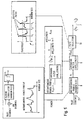
- Fig. 4 shows the functional block diagram of a rake receiver.
- the rake receiver 1 is a fundamental element of the mobile station demodulator.
- a typical Rake receiver comprises three basic algorithms: a path searcher 3 a channel estimator 4 and a combiner 5.
- the path searcher 3 estimates the number and locations (time delays) 7 of the paths in a frequency selective channel. These delay estimates 7 are then used by the channel estimotor4 to get the complex coefficients Ci of the propagation channel.
- the combiner coherently combines the channel coefficient estimates obtained for each path to enhance the useful data signal information before detection.
- the principle of the Rake receiver is to combine the maximum number of different paths, by introducing delays in the receiver. These paths and delays ( ⁇ i is the delay of the i th path) are respectively detected and estimated by the functional block called path searcher 3.
- the second block of the Rake receiver is the channel estimator 4, which performs the estimation of the channel impulse response over all the detected paths by the path searcher 3. These estimations are also used to combine coherently each received path. This combination of the paths is performed by the combiner 5.
- the path-searcher algorithm is an important functional part in a Rake receiver.
- the aim of this algorithm is to estimate the number and the location of the paths in a multipath channel. These estimations are also used by the channel estimator 4 and the combiner. Those are connected to the path searcher 3.
- the path searcher 3 uses the pilot sequence 21 of the Dedicated Physical Channel 20. This pilot sequence is split on I&Q branches, spread with a Hadamard code and scrambled with a Gold code, according to the ETSI specification.
- the path searcher needs a power profile prior to the path selection operation.
- the structure of a path searcher 3 in details is shown in figure 5.
- the path searcher comprises an instantaneous profile analyzer 8 connected to an averaging filter 9 and a path selector 10.
- the instantaneous profile analyzer 8 extract the energy distribution of the measured signal of the slot i of the pilot sequence 21.
- the result is an instantaneous power profile shown in fig. 5 over a definite window size.
- To get a more reliable profile it is computed by noncoherent averaging the instantaneous channel profiles performed on a slot by slot-basis.
- the noncoherent averaging is performed over AVG_LENGTH slots by an averaging filter 9.
- the instantaneous profiles Pi, p1+1... are used.
- the last step is the path selector that selected the pathes with power densities above a predefined threshold.
- the result is a set of delays.
- Fig 7 is a parallel configuration of a receiver.
- the pilot sequences of these channels are connected to a selection device 12 taking a probe of each pilot sequence for further analysis.
- These single probes connected to a parallel-serial converter 11.
- the result is a data stream including channel information of more than one single pilot sequence. This data stream is analyzed in the way describes above.
- the P/S converter 1 is connected to an instantaneous profile analyzer 8, an averaging filter 9 and a path selector 10.
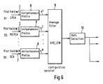
- FIG. 6 A second realization of the inventional idea is explained in figure 6.
- the incoming pilot sequences are inputted in parallel instantaneous profile analyzers 8.
- the analyzers 8 extract the instantaneous profiles P N i for each pilot sequence received.
- the single power profiles are averaged in one averaging filter 9 and the result selected by a path selector 10.
Landscapes
- Engineering & Computer Science (AREA)
- Computer Networks & Wireless Communication (AREA)
- Signal Processing (AREA)
- Mobile Radio Communication Systems (AREA)
- Radio Transmission System (AREA)
Claims (3)
- Empfänger für eine CDMA-Funkübertragung, umfassend einen Rake-Receiver (1) mit einem Wegesucher (3), einer Kanalschätzfunktion (4) und einem Kombinator (5) zum Auswählen optimaler Kanalwege, wo der Wegesucher (3), der zum Auswählen eines Satzes von Wegeverzögerungen (7) angeordnet ist, einen Augenblicksprofilanalysator (8), einen Mittelwertfilter (9) und einen Wegeselektor (10) umfaßt, dadurch gekennzeichnet, daß mindestens zwei Augenblicksprofilanalysatoren (8) mit dem Mittelwertfilter (9) verbunden sind.
- Empfänger nach Anspruch 1, außerdem umfassend Einrichtungen zum Durchführen der parallelen Extraktion von Daten von parallelen empfangenen Kanälen, die Pilotfolgen einschließen.
- Empfänger nach Anspruch 1, der außerdem angepaßt ist, um Signale zu empfangen, die auf Kanälen mit konstanten Bitraten und/oder Kanälen mit sich ändernden Bitraten übertragen wurden.
Priority Applications (5)
| Application Number | Priority Date | Filing Date | Title |
|---|---|---|---|
| EP99440158A EP1069696B1 (de) | 1999-06-24 | 1999-06-24 | Empfänger und Verfahren mit verbesserter Leistung für CDMA Übertragung |
| DE69933371T DE69933371T2 (de) | 1999-06-24 | 1999-06-24 | Empfänger und Verfahren mit verbesserter Leistung für CDMA Übertragung |
| US09/377,032 US6496494B1 (en) | 1999-06-24 | 1999-08-19 | Receiver and method with enhanced performance for CDMA transmission |
| JP2000173061A JP2001036432A (ja) | 1999-06-24 | 2000-06-09 | Cdma伝送用の向上した性能を有する受信機と方法 |
| CNB001187430A CN1186884C (zh) | 1999-06-24 | 2000-06-23 | 用于码分多址传输的具有增强性能的方法和接收机 |
Applications Claiming Priority (1)
| Application Number | Priority Date | Filing Date | Title |
|---|---|---|---|
| EP99440158A EP1069696B1 (de) | 1999-06-24 | 1999-06-24 | Empfänger und Verfahren mit verbesserter Leistung für CDMA Übertragung |
Publications (2)
| Publication Number | Publication Date |
|---|---|
| EP1069696A1 EP1069696A1 (de) | 2001-01-17 |
| EP1069696B1 true EP1069696B1 (de) | 2006-09-27 |
Family
ID=8242345
Family Applications (1)
| Application Number | Title | Priority Date | Filing Date |
|---|---|---|---|
| EP99440158A Expired - Lifetime EP1069696B1 (de) | 1999-06-24 | 1999-06-24 | Empfänger und Verfahren mit verbesserter Leistung für CDMA Übertragung |
Country Status (5)
| Country | Link |
|---|---|
| US (1) | US6496494B1 (de) |
| EP (1) | EP1069696B1 (de) |
| JP (1) | JP2001036432A (de) |
| CN (1) | CN1186884C (de) |
| DE (1) | DE69933371T2 (de) |
Families Citing this family (8)
| Publication number | Priority date | Publication date | Assignee | Title |
|---|---|---|---|---|
| JP3487842B2 (ja) * | 1999-07-15 | 2004-01-19 | インフィネオン テクノロジーズ アクチェンゲゼルシャフト | モバイル無線チャネルのチャネルインパルス応答を推定する方法 |
| US6801564B2 (en) * | 2000-02-23 | 2004-10-05 | Ipr Licensing, Inc. | Reverse link correlation filter in wireless communication systems |
| JP2002026768A (ja) * | 2000-07-07 | 2002-01-25 | Nec Corp | 通信装置 |
| US20020136234A1 (en) * | 2001-02-14 | 2002-09-26 | Hakan Eriksson | Tuning the fingers of rake receiver |
| SG114534A1 (en) * | 2002-03-12 | 2005-09-28 | Oki Techno Ct Singapore Pte | Reduced-complexity multipath interference cancellation |
| US7142586B2 (en) * | 2002-09-18 | 2006-11-28 | Telefonaktiebolaget Lm Ericsson (Publ) | Robust delay estimation architecture |
| US7349461B2 (en) * | 2003-02-13 | 2008-03-25 | Qualcomm Incorporated | Efficient back-end channel matched filter (CMF) |
| EP1655854A1 (de) * | 2004-11-03 | 2006-05-10 | Alcatel | Verfahren zur Berechnung des Verzögerungsprofils in einem zellularen Kommunicationssystem. |
Family Cites Families (8)
| Publication number | Priority date | Publication date | Assignee | Title |
|---|---|---|---|---|
| JP2655068B2 (ja) * | 1993-12-30 | 1997-09-17 | 日本電気株式会社 | スペクトラム拡散受信機 |
| US5671221A (en) * | 1995-06-14 | 1997-09-23 | Sharp Microelectronics Technology, Inc. | Receiving method and apparatus for use in a spread-spectrum communication system |
| DE69629633T2 (de) * | 1995-07-19 | 2004-06-17 | Nec Corp. | Vielfaltnachrichtenübertragungssystem mit Kodemultiplexvielfachzugriff |
| CN1092431C (zh) * | 1995-11-29 | 2002-10-09 | Ntt移动通信网株式会社 | 分集接收机及其控制方法 |
| JP2934185B2 (ja) * | 1996-03-15 | 1999-08-16 | 松下電器産業株式会社 | Cdmaセルラ無線基地局装置および移動局装置および送信方法 |
| JP3310160B2 (ja) * | 1996-03-29 | 2002-07-29 | 松下電器産業株式会社 | スペクトラム拡散方式受信装置 |
| JPH1051354A (ja) * | 1996-05-30 | 1998-02-20 | N T T Ido Tsushinmo Kk | Ds−cdma伝送方法 |
| JP3720141B2 (ja) * | 1996-10-01 | 2005-11-24 | 松下電器産業株式会社 | 移動体通信方法およびその装置 |
-
1999
- 1999-06-24 DE DE69933371T patent/DE69933371T2/de not_active Expired - Lifetime
- 1999-06-24 EP EP99440158A patent/EP1069696B1/de not_active Expired - Lifetime
- 1999-08-19 US US09/377,032 patent/US6496494B1/en not_active Expired - Lifetime
-
2000
- 2000-06-09 JP JP2000173061A patent/JP2001036432A/ja active Pending
- 2000-06-23 CN CNB001187430A patent/CN1186884C/zh not_active Expired - Lifetime
Also Published As
| Publication number | Publication date |
|---|---|
| JP2001036432A (ja) | 2001-02-09 |
| DE69933371D1 (de) | 2006-11-09 |
| CN1287414A (zh) | 2001-03-14 |
| EP1069696A1 (de) | 2001-01-17 |
| US6496494B1 (en) | 2002-12-17 |
| CN1186884C (zh) | 2005-01-26 |
| DE69933371T2 (de) | 2007-01-11 |
Similar Documents
| Publication | Publication Date | Title |
|---|---|---|
| EP1069697B1 (de) | Empfänger und Verfahren für CDMA Übertragung mit verbessertem Wegsucher | |
| EP0779000B1 (de) | Kodeerfassungsverfahren in einer cdma-kommunikationsanordnung unter verwendung mehrerer walsh kanäle | |
| CA2174912C (en) | Transmission diversity system | |
| EP1210803B1 (de) | Auf schätzung der leistungspektraldichte basierte festellung der datenrate | |
| KR100335689B1 (ko) | 통신 단말 장치 및 무선 수신 방법 | |
| AU1306400A (en) | A cdma receiver that shares a tracking device among multiple rake branches | |
| KR100355327B1 (ko) | 통신 단말 장치 및 그와 통신하는 기지국 장치와 무선 통신 방법 | |
| US20060203894A1 (en) | Method and device for impulse response measurement | |
| EP0844743A2 (de) | Spreizspektrumempfänger zur Verwendung in einem Kommunikationssystem | |
| US20030053522A1 (en) | Method and device for estimating a channel propagation | |
| EP1069696B1 (de) | Empfänger und Verfahren mit verbesserter Leistung für CDMA Übertragung | |
| KR100737792B1 (ko) | 무선 전기 통신국용 수신기 및 그 통신 방법 | |
| US7352799B2 (en) | Channel estimation in spread spectrum system | |
| EP1066689B1 (de) | Empfangsverfahren und Empfänger | |
| US7688774B2 (en) | Interference cancellation in radio system receiver | |
| KR100504360B1 (ko) | 수신기 및 수신 방법 | |
| US20050018758A1 (en) | Receiving spread spectrum signal in radio system | |
| KR100725276B1 (ko) | 데이터 전송 방법 및 수신기 | |
| EP1672808B1 (de) | Verzögerungswertauswahl für einen RAKE-Empfänger | |
| CA2202621C (en) | Code acquisition in a cdma communication system using multiple walsh channels | |
| Zakharov et al. | Detection of preamble of random access burst in W-CDMA system | |
| KR20070121002A (ko) | Rake 수신기에 대하여 지연 값들을 선택하는 방법 및컴퓨터 판독가능 매체 | |
| HK1013375B (en) | Code acquisition in a cdma communication system using multiple walsh channels | |
| WO2006066765A1 (en) | Selecting peak delay values for a rake receiver |
Legal Events
| Date | Code | Title | Description |
|---|---|---|---|
| PUAI | Public reference made under article 153(3) epc to a published international application that has entered the european phase |
Free format text: ORIGINAL CODE: 0009012 |
|
| 17P | Request for examination filed |
Effective date: 19991222 |
|
| AK | Designated contracting states |
Kind code of ref document: A1 Designated state(s): DE ES FI FR GB IT SE |
|
| AX | Request for extension of the european patent |
Free format text: AL;LT;LV;MK;RO;SI |
|
| AKX | Designation fees paid |
Free format text: DE ES FI FR GB IT SE |
|
| 17Q | First examination report despatched |
Effective date: 20041122 |
|
| GRAP | Despatch of communication of intention to grant a patent |
Free format text: ORIGINAL CODE: EPIDOSNIGR1 |
|
| GRAS | Grant fee paid |
Free format text: ORIGINAL CODE: EPIDOSNIGR3 |
|
| GRAA | (expected) grant |
Free format text: ORIGINAL CODE: 0009210 |
|
| AK | Designated contracting states |
Kind code of ref document: B1 Designated state(s): DE ES FI FR GB IT SE |
|
| PG25 | Lapsed in a contracting state [announced via postgrant information from national office to epo] |
Ref country code: IT Free format text: LAPSE BECAUSE OF FAILURE TO SUBMIT A TRANSLATION OF THE DESCRIPTION OR TO PAY THE FEE WITHIN THE PRE;WARNING: LAPSES OF ITALIAN PATENTS WITH EFFECTIVE DATE BEFORE 2007 MAY HAVE OCCURRED AT ANY TIME BEFORE 2007. THE CORRECT EFFECTIVE DATE MAY BE DIFFERENT FROM THE ONE RECORDED.SCRIBED TIME-LIMIT Effective date: 20060927 Ref country code: FI Free format text: LAPSE BECAUSE OF FAILURE TO SUBMIT A TRANSLATION OF THE DESCRIPTION OR TO PAY THE FEE WITHIN THE PRESCRIBED TIME-LIMIT Effective date: 20060927 |
|
| REG | Reference to a national code |
Ref country code: GB Ref legal event code: FG4D |
|
| REF | Corresponds to: |
Ref document number: 69933371 Country of ref document: DE Date of ref document: 20061109 Kind code of ref document: P |
|
| PG25 | Lapsed in a contracting state [announced via postgrant information from national office to epo] |
Ref country code: SE Free format text: LAPSE BECAUSE OF FAILURE TO SUBMIT A TRANSLATION OF THE DESCRIPTION OR TO PAY THE FEE WITHIN THE PRESCRIBED TIME-LIMIT Effective date: 20061227 |
|
| PG25 | Lapsed in a contracting state [announced via postgrant information from national office to epo] |
Ref country code: ES Free format text: LAPSE BECAUSE OF FAILURE TO SUBMIT A TRANSLATION OF THE DESCRIPTION OR TO PAY THE FEE WITHIN THE PRESCRIBED TIME-LIMIT Effective date: 20070107 |
|
| ET | Fr: translation filed | ||
| RAP2 | Party data changed (patent owner data changed or rights of a patent transferred) |
Owner name: ALCATEL LUCENT |
|
| PLBE | No opposition filed within time limit |
Free format text: ORIGINAL CODE: 0009261 |
|
| STAA | Information on the status of an ep patent application or granted ep patent |
Free format text: STATUS: NO OPPOSITION FILED WITHIN TIME LIMIT |
|
| 26N | No opposition filed |
Effective date: 20070628 |
|
| REG | Reference to a national code |
Ref country code: FR Ref legal event code: GC Effective date: 20140717 |
|
| REG | Reference to a national code |
Ref country code: FR Ref legal event code: PLFP Year of fee payment: 17 |
|
| REG | Reference to a national code |
Ref country code: FR Ref legal event code: CA Effective date: 20150521 |
|
| REG | Reference to a national code |
Ref country code: FR Ref legal event code: CA Effective date: 20150521 |
|
| REG | Reference to a national code |
Ref country code: FR Ref legal event code: PLFP Year of fee payment: 18 |
|
| REG | Reference to a national code |
Ref country code: FR Ref legal event code: PLFP Year of fee payment: 19 |
|
| REG | Reference to a national code |
Ref country code: FR Ref legal event code: PLFP Year of fee payment: 20 |
|
| PGFP | Annual fee paid to national office [announced via postgrant information from national office to epo] |
Ref country code: DE Payment date: 20180625 Year of fee payment: 20 |
|
| PGFP | Annual fee paid to national office [announced via postgrant information from national office to epo] |
Ref country code: FR Payment date: 20180620 Year of fee payment: 20 |
|
| PGFP | Annual fee paid to national office [announced via postgrant information from national office to epo] |
Ref country code: GB Payment date: 20180620 Year of fee payment: 20 |
|
| REG | Reference to a national code |
Ref country code: DE Ref legal event code: R071 Ref document number: 69933371 Country of ref document: DE |
|
| REG | Reference to a national code |
Ref country code: GB Ref legal event code: PE20 Expiry date: 20190623 |
|
| PG25 | Lapsed in a contracting state [announced via postgrant information from national office to epo] |
Ref country code: GB Free format text: LAPSE BECAUSE OF EXPIRATION OF PROTECTION Effective date: 20190623 |