EP1028515A1 - Permanentmagnetgenerator - Google Patents
Permanentmagnetgenerator Download PDFInfo
- Publication number
- EP1028515A1 EP1028515A1 EP98950414A EP98950414A EP1028515A1 EP 1028515 A1 EP1028515 A1 EP 1028515A1 EP 98950414 A EP98950414 A EP 98950414A EP 98950414 A EP98950414 A EP 98950414A EP 1028515 A1 EP1028515 A1 EP 1028515A1
- Authority
- EP
- European Patent Office
- Prior art keywords
- support
- stator
- drive
- rotary shaft
- magnetic body
- Prior art date
- Legal status (The legal status is an assumption and is not a legal conclusion. Google has not performed a legal analysis and makes no representation as to the accuracy of the status listed.)
- Withdrawn
Links
Images


Classifications
-
- H—ELECTRICITY
- H02—GENERATION; CONVERSION OR DISTRIBUTION OF ELECTRIC POWER
- H02K—DYNAMO-ELECTRIC MACHINES
- H02K7/00—Arrangements for handling mechanical energy structurally associated with dynamo-electric machines, e.g. structural association with mechanical driving motors or auxiliary dynamo-electric machines
- H02K7/18—Structural association of electric generators with mechanical driving motors, e.g. with turbines
- H02K7/1807—Rotary generators
-
- H—ELECTRICITY
- H02—GENERATION; CONVERSION OR DISTRIBUTION OF ELECTRIC POWER
- H02K—DYNAMO-ELECTRIC MACHINES
- H02K21/00—Synchronous motors having permanent magnets; Synchronous generators having permanent magnets
- H02K21/12—Synchronous motors having permanent magnets; Synchronous generators having permanent magnets with stationary armatures and rotating magnets
-
- H—ELECTRICITY
- H02—GENERATION; CONVERSION OR DISTRIBUTION OF ELECTRIC POWER
- H02K—DYNAMO-ELECTRIC MACHINES
- H02K7/00—Arrangements for handling mechanical energy structurally associated with dynamo-electric machines, e.g. structural association with mechanical driving motors or auxiliary dynamo-electric machines
- H02K7/18—Structural association of electric generators with mechanical driving motors, e.g. with turbines
-
- H—ELECTRICITY
- H02—GENERATION; CONVERSION OR DISTRIBUTION OF ELECTRIC POWER
- H02K—DYNAMO-ELECTRIC MACHINES
- H02K16/00—Machines with more than one rotor or stator
-
- H—ELECTRICITY
- H02—GENERATION; CONVERSION OR DISTRIBUTION OF ELECTRIC POWER
- H02K—DYNAMO-ELECTRIC MACHINES
- H02K53/00—Alleged dynamo-electric perpetua mobilia
Definitions
- the present invention relates generally to a permanent magnetic generator which can generate electricity by the use of a drive motor.
- the permanent magnetic generator can be prevented to happen to a cogging phenomenon (the revolving with a trembling caused by an attracted phenomenon of the magnetic force when a motor is started), the cost for manufacturing and its weight can be reduced.
- the present invention is suitable for mounting to real property or movable property such as a building, a mountain hut, a ship, an automobile, or the like.
- a generator comprises an annular magnets (rotor) disposed North and South poles mutually to the direction of rotation, a stator (generative coil housing) have annular coils therein with projections (yoke projection) formed of the silicon steel plate as many poles, five pieces for example as the rotor into the annular magnet and silts which are formed on the projections to the same direction of projection as respectively to decrease the electromotive force on the projection.
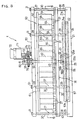
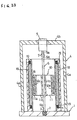
- the above-mentioned permanent magnetic generator comprises a support member 4 further which is composed of a pair of stationary columns 4a, 4a fixedly provided at the base 1 and a support arm 4b disposed horizontally and fixed to the upper ends of the columns 4a, 4a; a drive motor 5 which is supported fixedly at the support arm 4b of the support member 4 such that the drive motor 5 is centrally located with respect to the axis of the permanent magnetic rotor 10; a rotary shaft having an elongated bar-like shape, the upper end 6a of the rotary shaft 6 coaxially connected to the output shaft 5a of the drive motor 5 via a coupling 7, while the lower end 6b of the rotary shaft 6 entering an inverted-conical depression 3 to be supported by the bearing at the base 1; a permanent magnetic rotor 10 fixed to the rotary shaft, having a plurality of permanent magnets 12a, 12b, or the like; and a stator 15 having a cylindrical shape and which is disposed on the base 1 such that a predetermined gap 16
- the permanent magnetic rotor 10 is composed of a synthetic resin mold 11 and a plurality of permanent magnets 12a, 12b, 12c, and 12d.
- the synthetic resin mold 11 is fixedly disposed on the central portion of the rotary shaft 6, and each end surface thereof has a wheel-like shape.
- the permanent magnets 12a, 12b, 12c, and 12d are circumferentially arranged within an outer tubular portion 11a of the synthetic resin mold 11.
- the synthetic mold 11 is further composed of an outer tubular portion 11a, an inner tubular fixing portion 11b through which the rotary shaft 6 penetrates, and the connection portions 11c radially connect the inner tubular fixing portion 11b and the outer tubular portion 11a.
- the permanent magnet generator of the present invention is a reformed generator to the above-mentioned invention to efficiently generate electricity in a still more amount.
- the present invention provides a permanent magnetic generator which comprises a base 21, a stator member 35, a drive-motor support 50, a rotoary shaft 55, a rotor 60, a second magnet body 56, a bearing member 80, and a drive motor 70.
- the stator member 35 is horizontally disposed above the base 21 through support members 27 and has a stator support 36.
- the drive- motor support 50 is horizontally disposed and fixed to the support members 27 such that a space 61 is formed above the stator member 35.
- the rotary shaft 55 penetrtes a first center hole 42 formed in the stator support 36 and a second center hole 51 formed in the drive-motor support 50 and is supported by means of bearing 43 and 52.
- the rotor 60 is fixed to the rotary shaft 55 to be located within the space 61 and has annular permanent magnets 65 that face stator windings 38 of the stator member 35.
- the second magnet body 56 is fixedly attached to the projected lower end 55a of the rotary shaft 55 such that the second magnetic body 56 floats due to a repulsive force generated between the first and second magnetic bodies 23 and 56.
- the bearing member 80 is attached to the drive-motor support 50 in order to support the rotary shaft 55 urged upward through the second magnetic body 56.
- the drive motor 70 is fixed to the drive-motor support 50 and is adapted to rotate the rotary shaft 55 through power transmission means 74 and 75. Therefore, the rotary shaft can be improved to the performance for its rotation.
- the present invention provides a permanent magnetic generator including a rotor 60 which further comprises: a rotary plate 62, annular steel plates 64, and annular permanent magnets 65.
- the rotary plate 62 is horizontally disposed and fixed to the rotary shaft 55.
- the annular steel plates 64 are integrally fixed to the lower surface of the rotary plate 62 such that they are opposed to conductor attachment blocks 37 of the stator member 35.
- the annular permanent magnets 65 are integrally fixed to the lower surface of the rotary plate 62 such that the annular steel plates 64 and the annular permanent magnets 65 are alternately arranged and are opposed to stator windings 38 of the conductor attachment blocks 37 in a non-contatng state. Therefore, a strong magnetic field can be generated within the space 61, and the rotary shaft can be improved to the performance for its rotation.
- the present invention provides a permanent magnetic generator with comprises a first magnetic body 23 fixedly provided on a base 21, a stator member 35, a drive-motor support 50B, a rotarty shaft 55B, a rotor 60, a second magnetic body 56B, and a drive motor 70B.
- the stator member 35 is horizontally disposed above the base21 through support members 27 and has a stator support 36.
- the drive-motor support 50 is horizontally disposed and fixed to the support members 27 such that a space 61 is formed above the stator member 35.
- the rotary shaft 55B penetrtes a first center hole 42 formed in the stator support 36 and a second center hole 51 formed in the drive-motor support 50 and is supported by means of bearing 43 and 52.
- the rotor 60 is fixed to the rotary shaft 55B to be located within the space 61 and has annular permanent magnets 65 that face stator windings 38 of the stator member 35.
- the second magnetic body 56B is fixedly attached to the projected lower end 55a of the rotary shaft 55B such that the second magnetic body 56B floats due to a repulsive force generated between the first and second magnetic bodies 23 and 56.
- the drive motor 70B is vertically disposed on the upper surface of the drive-motor support 50B at the center portion thereof through a drive-motor support blocks 71B.
- the drive shaft 72B of the drive motor 70B is coaxial with and connected to the projected tip end of the rotary shaft 55B, with is urged upward through the second magnetic body. Therefore, the same effect as that of the invention described in Claim 1 can
- Figs. 1 to 8 illustrate in each explanation view showing a first embodiment of the present invention.
- Fig. 9 and Fig. 10 illustrate in each schematic explanation view showing a variation of main part of the first embodiment of the present invention.
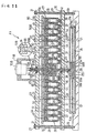
- Fig. 11 illustrates in a schematic cross-sectional explanation view showing a second embodi-ment of the present invention.
- Figs. 12 to 14 illustrate in each schematic explanation view showing an example of a prior art which is proposed by the present invention.
- Figs. 1 to 9 illustrate a first embodiment of a permanent magnetic generator X.
- Numeral 21 denotes a circular base.
- a circular depression 22 is formed over a large area on the upper surface 21a of the base 21.
- Numeral 23 denotes a first magnetic body fixedly provided in the depression 22.
- the first magnetic body 23 is composed of a stationary yoke 24 formed of iron and having a concave cross section fitted to the depression 22, and a flat magnet 25 fixed to the center portion of the bottom surface of the stationary yoke 24.
- the upper surface 21a of the base 21, the upper surface 24a of the circumferential edge portion of the stationary yoke 24, and the upper surface 25a of the magnet 25 are located on a circumferentially common plane.
- the magnet 25 has a south pole on the side of the upper surface 25a and a north pole on the side of the lower surface 25b. Accordingly, due to the effect of the polarity (north pole) of the maagnet 25, a north pole is formed in the vicinity of the upper surface 24a of the circumferential edge portion of the stationary yoke 24 having a function for generating magnetism.
- Numeral 27 denotes each of a plurality of support members which are vertically dIsposed on the base 21.
- six support members 27 are povided along the circumferential edge of the base 21 at predetermined intervals.
- Numeral 28 denotes a support shaft having an external thread at either end.
- the support shaft 28 is fixedly screwed into a tapped hole formed at the circumferential edge of the base 21.
- Numeral 29 denotes a lower support pipe which is fitted onto a lower portion of the support shaft 28.
- Numeral 30 denotes an upper support pipe which is fitted onto an upper portion of the support shaft 28 such that the stator member 35 is interposed between the lower and upper support pipes 29 and 30.
- Numeral 31 denotes a lock nut which is in screw engagement with the projected upper end of the support shaft 28 in order to fix the drive-motor support to the upper support pipe 30.
- the upper support pipe 30 has a length approximately double that of the lower support pipe 29, and the support shaft 28 penetrates the support pipes 29 and 30.
- the stator member 35 is mainly composed of a circular, nonmagnetic stator support 36, a plurality of (lots of) nonmagnetic conductor attachment blocks 37, and a plurality of stator windings 38.
- the stator support 36 is fixedly supported by means of the support members 27.
- the conductor attachment blocks 37 are radially and circumferentially disposed on the upper surface of the stator support 36 such that a predetermined space is formed between adjacent attachment blocks 37.
- the stator windings 38 (one generating coil on the whole) are fixedly provided in the conductor attachment blocks 37.
- diamagnetic material used herein means feeble magnetic substance (substain contains little magnetic substance) and material which is lighter than iron, regardless of whether the substance is nonferrous metal (such as titanium, stainless, or the like) or a nonmetal (such as synthetic resin, ceramics, cloth,or paper).
- the nonmagnetic stator support 36 in this embodiment is composed of a lower support 40 formed of wood and horizontally disposed to face the upper surface 21a of the base 21, and an upper support 41 formed of synthetic resin and integrally fixed to the upper surface of the lower support 40.
- the supports 40 and 41 are supported by mean of the support shafts 28 to be located on the upper ends of the lower support pipes 29 of the support members 27.
- a through-hole serving as a first center hole 42 is formed in the stator support 36.
- a first ball bearing 43 is provided within the first center hole 42 at a stepped portion thereof.
- a large number of engagement grooves 44 for receiving the conductor attachment blocks are formed radially and circumferentially on the upper surface of the upper support 41 at predetermined intervals.
- Each of the nonmagnetic conductor attachment blocks 37 in this embodiment generally has a shape of a vertically elongated block having trapezoidal or fan-shaped upper and lower end surfaces.
- Numeral 45 denotes a vertical elongated hole that penetrates the conductor attachment blocks 37 in a redial direction (from front surface 37a to back surface 37b) with respect to a rotary shaft 55, which will be described later.
- the vertical elongated hole 45 is formed at an approximate center portion of the conductor attachment blocks 37.
- Numeral 46 denotes a through-hole which is formed from the trapezoidal upper surface 37c toward the vertical elongated hole 45.
- the through-hole 46 perpendicularly intersects the vertical elongated hole 45 to communicate therewith.
- Numeral 47 denotes an engagement portion which is projected from the trapezoidal lower surface 37d of the conductor attachment blocks 37 and is engaged with the engagement grooves 44 of the upper support 41.
- Each of the stator windings 38 is shaped in a form of an elongated tubular body (bobbinless coil) having a track-shaped opposite ends.
- the stator windings 38 is inserted into the above-mentioned vertical elongated hole 45, and fixed by means of a fixing pin 46 inserted into the through-hole 46.
- the stator winding 38 has a cavity portion 49 which penetrates the stator winding 38.
- the conductor attachment blocks 37 is made of synthetic resin to reduce its weight.
- Numeral 50 denotes a drive-motor support that is horizontally disposed and fixed to the upper ends of the support members 27.
- the drive-motor support 50 is supported by mean of the support shafts 28 to be located on the upper ends of the upper support pipes 30 of the support members 27 and is fixed by means of lock nuts 31 that are in screw engagement with the support shafts 28.
- a through-hole serving as a second center hole 51 is formed in the drive-motor support 50.
- a second ball bearing 52 is provided within the second center hole 51 at a stepped portion thereof.
- the drive-motor support 50 is also made of wood or synthetic resin to reduced its weight.
- Numeral 55 denotes a rotary shaft journaled by means of the first ball bearing 43 of the stator support 36 and the second ball bearing 52 of the drive-motor support 50.
- a lower end portion 55a of the rotary shaft 55 penetrates the first center hole 42 of the stator support 36 and projects to the vicinity of the magnet 25 of the first magnetic bodt 23. Meanwhile, an upper end portion of the rotary shaft 55 penetrates the second center hole 51 of the drive-motor support 50.
- the projected tip endportion of the rotary shaft 55 is sharpened into a conical shape.
- the second magnetic body 56 is composed of a floating yoke 57 formed of iron and having an inverted concave cross section, and a flat floating magnet 58 fixed to the center portion of the inner wall of the floating yoke 57.
- the bottom surface 57a of the circumferential edge portion of the floating yoke 57 and the lower surface 58a of the floating magnet 58 are located on a substantially common plane.
- the floating magnet 58 has a south pole on the side of the lower surface 58a and a north pole on the side of the upper surface 58b. Accordingly, due to the effect of the polarity (north pole) of the floating magnet 58, a north pole is formed in the vicinity of the lower surface 57a of the circumferential edge portion of the floating yoke 57. Therefore, the rotary shaft 55 is always urged upward through the second magnet body 56, which repulses against the first magnetic body 23.
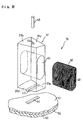
- Numeral 60 denotes a rotor formed of iron.
- the rotor 60 is fixed to the rotary shaft 55 to be located within a space provided between the stator support 36 of the stator member 35 and the drive-motor support 50.
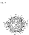
- the stator 60 in the present embodiment is composed of a horizontal rotary plate 62, a sleeve 63, a plurality of (four plates in all) annular steel plates 64, and annular permanent magnets 65.
- the rotary plate 62 is fixed to the rotary shaft 55 at a portion near the upper end of the rotary shaft 55.
- the sleeve 63 is fixedly attached on the lower surface of the rotary plate 62 at the center thereof and fitted onto the rotary shaft 55.
- the annular steel plates 64 are integrally attached to the lower surface of the rotary plate 62 such that the steel plate 64 are nested (concentric circle) around the sleeve 63 and that a predetermined space is formed between adjacent two steel plates 64 in order to receive two conductor attachment blocks 37 therebetween.
- the permanent magnets 65 are integrally attached to the lower surface of the rotary plate 62 such that the annular steel plates 64 and the annular permanent magnets 65 alternately face the stator windings 38 of the conductor attachment blocks 37 in a non-contacting state.
- the plurality of annular permanent magnets 65 and the plurality of annular plates 64 are alternately enter such that the annular permanent magnet 65 first enters the first space, the annular steel plates 64 then enter the second space, the annular permanent magnet 65 then enters the third space, the annular steel plates 64 then enter the fourth space, etc. Therefore, at least one conductor attachment blocks 37 is sandwiched between the annular permanent magnet 65 and the annular steel plate 64 in a non-contacting state.
- the sleeve 63 has a large thickness or diameter in order to increase the mass of the rotor 60 to thereby obtain a so-called flywheel effect, as well as to prevent vibration and deflection of the rotor 60.
- Each of the annular permanent magnets 65 concentrically disposed on the lower surface of the rotary plate 62 is composed of a plurality of curved permanent magnet plates (not indicated by reference numerals) that are combined such that north and south poles are alternately formed in the circumferential direction (such that the north and south poles are alternately formed on both the inner surface side and the outer surface side of the permanent magnet plates).
- the annular permanent magnets 65 are fixedly fitted into the fitting windows of annular attachment walls 66 formed of iron and concentrically and integrally attached to the lower surface of the rotary plate 62.
- Numeral 70 denotes a drive motor fixedly disposed above the drive-motor support 50 through a drive-motor support bracket 71.
- This drive motor is started through use of a power supply, not illustrate, such as a battery a condenser, a home power supply, or the like.
- the drive motor 70 is not coaxial with the rotary shaft 55, but is disposed in the vicinity of the rotary shaft 55 such that the drive shaft 72 of the drive motor 70 is directed downward.
- a lower end portion of the drive shaft 72 is journaled by means of a third ball bearing 73 provided on the upper surface of the drive-motor support 50. Further, a drive gear 74 is fixedly provided on the drive shaft 72 at a portion near the lower end thereof. The drive gear 74 is in meshing engagement with a driven gear 75 fixed to the projected upper end of the rotary shaft 55.
- Numeral 80 denotes a bearing member attached to the central portion of the upper surface of the drive-motor support 50 in order to support the projected tip end of the rotary shaft 55.
- the bearing member 80 is composed of a bearing block 81 having an angle-like shape or a frame-like shape and a fourth ball bearing 82 which is provided on the inner wall surface of the upper horizontal wall of the bearing block 81 and supports the shaped tip end of the rotary shaft 55.
- the list and second ball bearings 43 and 52 bear only a tangential friction force in the circumferential direction of the rotary shaft 55. Further, the fourth bearing 82 bears only a friction force generated due to upward abutting motion of the sharpened tip end of the rotary shaft 50. Therefore, as compared with ordinary machines and devices, the rotary shaft 50 rotates smoothly in a state in which the friction resistance with the bearing member is decreased.
- the stator support 36 of the stator member 35 is composed of a lower support 40 formed of wood and the upper support 41 formed of synthetic resin, however, the lower and upper supports 40 and 41 may be formed integrally through use of a synthetic resin material or a ceramic material.
- stator support 36 of the stator member 35 and the conductor attachment blocks 37 may be formed integrally through use of a synthetic resin material or a ceramic material.
- tip end portion of the rotary shaft 60 is sharply pointed as in the case of a nail, however, the bearing 82 supports to the tip end thereof may be formed in an inverted-conical depression 3.
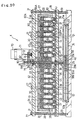
- the plurality of conductor attachment blocks 37 disposed on the upper surface of the stator support 36 of the stator member 35 at predetermined intervals in the circumferential direction may be integrally connected through an annular fixing plate 85.
- the annular fixing plate 85 is fixed to the upper surfaces 37c of the conductor attachment blocks 37 disposed in the circumferential direction by means of fixing pins 48A inserted into attachment through-holes 86 formed at predetermined intervals.
- At least one of the annular steel plates 64 of the rotor 60A may be formed to have a wall thickness greater than that of other annular steel plates 64 to produce an effect of flywheel therein.
- an outermost annular steel plate 64A has a slightly larger wall thickness to obtain a sufficient inertia moment and flywheel effect
- the rotor 60A gets a large inertia force so that the resistance by counter electromotive force, when electricity is generated, is controlled by inertial moment and flywheel effect due to the rotor 60A even if the drive motor 70 stops.
- the permanent magnet 65 of the rotor 60 (60A) is a neodymium magnet, for example having BHmax of 41.1 MGO.
- Fig. 11 illustartes a second embodiment of the present invention; this is distinguished from the first embodiment in that a drive motor 70B is vertically disposed on the upper surface of the drive-motor support 50B at the center portion thereof through a drive-motor support blocks 71B, having a drive shaft 72B of the drive motor 70B which is coaxial with and connected to the projected tip end of the rotary shaft 55B, which is urged upward through the second magnetic body
- the coupling 90 having a fitting hole 91 formed in the shape of a square to a downward direction is attached fixedly to a projected end portion of the drive shaft 72B of the drive motor 70B. Therefore, the projected upper end portion, formed in a square shape, of the rotary shaft 55B which rises due to the repelling power with the second magnetic body 56B is always inserting into the fitting hole 91 of the coupling 90.
- the second magnetic body integrally provided to the rotary shaft rise up corresponding to the nature of poles of the first magnetic body adjasent the base so that the frictional resistance of rotary shaft to the bearing reduces it to a minimum.
- the rotor of the permanent magnetic generator has a large diameter and enough mass (weight), and it gets a large inertia moment,the resistance by a counter electromotive force is controlled by inertial moment and flywheel effect due to the permanent magnetic rotor, then, the permanent magnetic generator rotates and continues to generate even if there is no power source for driving far a limited time.
- the rotor have the anuular steel plate faces to the fixed winding of stator member, magnetic field produces into the space in more strong. Therefore, it can be improve to generate electricity in amount. Furthermore, in such embodiment that elongated fixed winding (bobbinless coil) is attached to the conductor fitting piece of the stator member, its weight can be reduced. In addition, in such embodiment that the stator member without the fixed winding is formed of nonmagnetic material a cogging phenomenon is slight.
- the present invetion is suitable for mounting to real property or movable property such as a building, a mountain hut, a ship, an automobile, or the like.
Landscapes
- Engineering & Computer Science (AREA)
- Power Engineering (AREA)
- Permanent Magnet Type Synchronous Machine (AREA)
- Iron Core Of Rotating Electric Machines (AREA)
- Connection Of Motors, Electrical Generators, Mechanical Devices, And The Like (AREA)
- Motor Or Generator Frames (AREA)
Applications Claiming Priority (4)
| Application Number | Priority Date | Filing Date | Title |
|---|---|---|---|
| JP31592097 | 1997-10-31 | ||
| JP9315920A JPH11136915A (ja) | 1997-10-31 | 1997-10-31 | 永久磁石型発電機 |
| PCT/JP1998/004865 WO1999023743A1 (fr) | 1997-10-31 | 1998-10-27 | Generateur a aimant permanent |
| US09/562,035 US6285103B1 (en) | 1997-10-31 | 2000-05-01 | Permanent magnetic generator |
Publications (2)
| Publication Number | Publication Date |
|---|---|
| EP1028515A1 true EP1028515A1 (de) | 2000-08-16 |
| EP1028515A4 EP1028515A4 (de) | 2003-01-02 |
Family
ID=26568470
Family Applications (1)
| Application Number | Title | Priority Date | Filing Date |
|---|---|---|---|
| EP98950414A Withdrawn EP1028515A4 (de) | 1997-10-31 | 1998-10-27 | Permanentmagnetgenerator |
Country Status (8)
| Country | Link |
|---|---|
| US (1) | US6285103B1 (de) |
| EP (1) | EP1028515A4 (de) |
| JP (1) | JPH11136915A (de) |
| CN (1) | CN1088937C (de) |
| AU (1) | AU9649098A (de) |
| TW (1) | TW417345B (de) |
| WO (1) | WO1999023743A1 (de) |
| ZA (1) | ZA989927B (de) |
Cited By (4)
| Publication number | Priority date | Publication date | Assignee | Title |
|---|---|---|---|---|
| WO2003075439A3 (en) * | 2002-03-05 | 2004-03-18 | Kazimierz Ziolko | Method and device for transforming mechanical energy into electrical energy or electrical energy into mechanical energy |
| EP2038989A4 (de) * | 2006-05-29 | 2011-08-03 | Kye Jung Park | Kernloser motor mit konzentrisch angeordneten rotoren und antriebsvorrichtung mit dem motor |
| ITMI20121982A1 (it) * | 2012-11-21 | 2014-05-22 | Maurizio Cassano | Dispositivo per la generazione di energia elettrica a rotori combinati con statori |
| WO2013149242A3 (en) * | 2012-03-30 | 2014-08-28 | Samuels Davian A | Generator comprising permanent magnets and conductors and method to produce electrical energy therewith |
Families Citing this family (9)
| Publication number | Priority date | Publication date | Assignee | Title |
|---|---|---|---|---|
| KR100442122B1 (ko) * | 2001-07-31 | 2004-07-30 | 한국전기연구원 | 영구 자석을 이용한 브러시리스 발전기 |
| US20040251757A1 (en) * | 2003-06-10 | 2004-12-16 | Porter James M. | High efficiency torque converter |
| JP2010525774A (ja) * | 2007-04-18 | 2010-07-22 | ゲ−ヨン パク | 同心円状に配置された回転子を有するモータ及び前記モータを備える駆動装置 |
| CN102035321B (zh) * | 2010-11-29 | 2013-09-04 | 深圳市大族激光科技股份有限公司 | 一种双边直驱无槽力矩电机 |
| DE102012020435A1 (de) * | 2012-10-18 | 2013-12-19 | Audi Ag | Elektrischer Dämpfer für ein Kraftfahrzeug |
| TW201544689A (zh) * | 2014-05-21 | 2015-12-01 | Lin Xu Guang | 磁浮式動力裝置 |
| JP6062134B1 (ja) * | 2016-04-07 | 2017-01-18 | 三菱電機株式会社 | 固定子および電動機 |
| WO2019204455A1 (en) * | 2018-04-19 | 2019-10-24 | Inductive Ventures Llc | Combination brake-generator inverted motor |
| TWI886953B (zh) * | 2024-05-15 | 2025-06-11 | 林碧霞 | 垂直軸風力發電裝置之發電機 |
Family Cites Families (11)
| Publication number | Priority date | Publication date | Assignee | Title |
|---|---|---|---|---|
| DE2103737C3 (de) * | 1971-01-27 | 1978-08-24 | Max 5060 Bergisch Gladbach Baermann | Magnetische Axiallagerung für Elektrizitätszähler |
| DE2108590A1 (de) * | 1971-02-23 | 1972-09-07 | Siemens Ag | Anordnung zur Lagerung einer hochtourig, insbesondere elektromotorisch angetriebenen Welle |
| JPS58142025A (ja) * | 1982-02-13 | 1983-08-23 | Toshiba Corp | スピンドル装置 |
| JPH0756616Y2 (ja) * | 1990-08-07 | 1995-12-25 | 株式会社ゼクセル | モータのロータマグネットの着磁構造 |
| DE4130016A1 (de) * | 1990-12-24 | 1993-03-11 | Erich Rabe | Elektronisch kommutierte gleichstrommaschine |
| US5314868A (en) * | 1991-08-06 | 1994-05-24 | Koyo Seiko Co., Ltd. | Bearing device |
| JPH08109867A (ja) * | 1994-10-07 | 1996-04-30 | Takashi Nosaka | 回転力増強装置とその発電装置 |
| JPH0953550A (ja) * | 1995-08-17 | 1997-02-25 | Denso Corp | 始動発電装置 |
| JPH09121522A (ja) * | 1995-10-23 | 1997-05-06 | Sawafuji Electric Co Ltd | フラット回転機 |
| CZ410497A3 (cs) * | 1996-12-20 | 1998-07-15 | W. Schlafhorst Ag Und Co. | Axiální uložení pro otevřený dopřádací rotor |
| JPH10336954A (ja) * | 1997-05-26 | 1998-12-18 | Mitsuhiro Fukada | 永久磁石型発電機 |
-
1997
- 1997-10-31 JP JP9315920A patent/JPH11136915A/ja active Pending
-
1998
- 1998-10-27 CN CN98812717A patent/CN1088937C/zh not_active Expired - Fee Related
- 1998-10-27 TW TW087117717A patent/TW417345B/zh not_active IP Right Cessation
- 1998-10-27 EP EP98950414A patent/EP1028515A4/de not_active Withdrawn
- 1998-10-27 WO PCT/JP1998/004865 patent/WO1999023743A1/ja not_active Ceased
- 1998-10-27 AU AU96490/98A patent/AU9649098A/en not_active Abandoned
- 1998-10-31 ZA ZA989927A patent/ZA989927B/xx unknown
-
2000
- 2000-05-01 US US09/562,035 patent/US6285103B1/en not_active Expired - Fee Related
Cited By (4)
| Publication number | Priority date | Publication date | Assignee | Title |
|---|---|---|---|---|
| WO2003075439A3 (en) * | 2002-03-05 | 2004-03-18 | Kazimierz Ziolko | Method and device for transforming mechanical energy into electrical energy or electrical energy into mechanical energy |
| EP2038989A4 (de) * | 2006-05-29 | 2011-08-03 | Kye Jung Park | Kernloser motor mit konzentrisch angeordneten rotoren und antriebsvorrichtung mit dem motor |
| WO2013149242A3 (en) * | 2012-03-30 | 2014-08-28 | Samuels Davian A | Generator comprising permanent magnets and conductors and method to produce electrical energy therewith |
| ITMI20121982A1 (it) * | 2012-11-21 | 2014-05-22 | Maurizio Cassano | Dispositivo per la generazione di energia elettrica a rotori combinati con statori |
Also Published As
| Publication number | Publication date |
|---|---|
| CN1088937C (zh) | 2002-08-07 |
| AU9649098A (en) | 1999-05-24 |
| ZA989927B (en) | 1999-05-05 |
| WO1999023743A1 (fr) | 1999-05-14 |
| EP1028515A4 (de) | 2003-01-02 |
| JPH11136915A (ja) | 1999-05-21 |
| TW417345B (en) | 2001-01-01 |
| US6285103B1 (en) | 2001-09-04 |
| CN1283321A (zh) | 2001-02-07 |
Similar Documents
| Publication | Publication Date | Title |
|---|---|---|
| US6285103B1 (en) | Permanent magnetic generator | |
| US6172438B1 (en) | Two-phase permanent-magnet electric rotating machine | |
| CN101501962B (zh) | 磁悬浮电动机和泵 | |
| BG99044A (en) | Rotary magnetic device | |
| KR102156481B1 (ko) | 자기부상 회전체를 포함하는 축방향 모터 | |
| JP2008545366A (ja) | トルクコンバータおよびトルクコンバータを使用するシステム | |
| JP2002335658A (ja) | モータ | |
| US4843268A (en) | Asymmetric field electromagnetic motor | |
| US4980590A (en) | Flat brushless motor with a back-yoke formed as an eccentric weight to induce vibrations | |
| JPH08178011A (ja) | フライホイール装置 | |
| RU2000113791A (ru) | Подвеска роторов генераторов в магнитном поле | |
| OA11375A (en) | Permanent magnet generator. | |
| US11108287B2 (en) | Spherical electromagnetic machine with two degrees of unconstrained rotational freedom | |
| US6958556B2 (en) | Structure of rotors in stepping motors | |
| US3421032A (en) | Synchronous reaction motor with deadshaft rotor mount | |
| JP2571775Y2 (ja) | 小型同期モータ | |
| KR101604637B1 (ko) | 양극평형운동을 이용한 시간차 발전기가 부착된 진공 전동기 | |
| KR100257778B1 (ko) | 브러시리스 모터 | |
| JPH0946964A (ja) | 発電装置 | |
| KR102685213B1 (ko) | 자석의 Metal Magnet Interaction (MMI) 현상을 이용한 이중척력 장치 | |
| EP1253703A1 (de) | Kraftanlage | |
| JP2005033973A (ja) | 磁石及び電磁石による駆動力発生装置及びこれを組み込んだ回転電機や駆動装置 | |
| JP2025054863A (ja) | 回転電気装置及び発電装置 | |
| US3525004A (en) | Magnetic drive | |
| KR100383576B1 (ko) | 편향된 자력선을 갖는 자석의 제조방법 및 그 자력을 이용한 동력장치 |
Legal Events
| Date | Code | Title | Description |
|---|---|---|---|
| PUAI | Public reference made under article 153(3) epc to a published international application that has entered the european phase |
Free format text: ORIGINAL CODE: 0009012 |
|
| 17P | Request for examination filed |
Effective date: 20000518 |
|
| AK | Designated contracting states |
Kind code of ref document: A1 Designated state(s): CH DE FR GB LI PT |
|
| A4 | Supplementary search report drawn up and despatched |
Effective date: 20021118 |
|
| AK | Designated contracting states |
Kind code of ref document: A4 Designated state(s): CH DE FR GB LI PT |
|
| RIC1 | Information provided on ipc code assigned before grant |
Free format text: 7H 02K 21/12 A, 7H 02K 7/18 B, 7H 02K 7/09 B |
|
| 18D | Application deemed to be withdrawn |
Effective date: 20030503 |