EP1028181A1 - Pot spinning machine and method for centrifugal spinning - Google Patents
Pot spinning machine and method for centrifugal spinning Download PDFInfo
- Publication number
- EP1028181A1 EP1028181A1 EP00100169A EP00100169A EP1028181A1 EP 1028181 A1 EP1028181 A1 EP 1028181A1 EP 00100169 A EP00100169 A EP 00100169A EP 00100169 A EP00100169 A EP 00100169A EP 1028181 A1 EP1028181 A1 EP 1028181A1
- Authority
- EP
- European Patent Office
- Prior art keywords
- spinning
- thread guide
- guide
- thread
- drive device
- Prior art date
- Legal status (The legal status is an assumption and is not a legal conclusion. Google has not performed a legal analysis and makes no representation as to the accuracy of the status listed.)
- Granted
Links
Images
Classifications
-
- D—TEXTILES; PAPER
- D01—NATURAL OR MAN-MADE THREADS OR FIBRES; SPINNING
- D01H—SPINNING OR TWISTING
- D01H1/00—Spinning or twisting machines in which the product is wound-up continuously
- D01H1/08—Spinning or twisting machines in which the product is wound-up continuously cup, pot or disc type, in which annular masses of yarn are formed by centrifugal action
Definitions
- the invention relates to a centrifuge spinning machine for Manufacture of yarn with the in the preamble of claim 1 mentioned features and a method for Centrifugal spinning of yarn with the in the preamble of Claim 9 mentioned features.
- centrifuge or pot spinning machine and a method of the generic type are known for example from DE 42 08 039 A1 and DE 43 24 039 A1.
- Centrifugal spinning machines of this type generally comprise a large number of spinning stations, each of which has a spin pot (centrifuge) which can be set in rotation.
- Such spinning stations are fed via a sliver drafting device, preferably a drafting device, sliver which is spun into a thread under the action of the spinning pot rotating about its central axis.
- the thread passes through a tubular thread guide and exits at its mouth, forming a thread leg.
- the thread is deposited in layers on the inner wall of the spinning pot as a so-called spinning cake. This placing of the spinning cake takes place by generating a relative movement between the thread guide and the spinning pot in the axial direction.
- This relative movement also referred to as a traversing movement, is generated by a drive device for the thread guide and / or the spinning pot.
- a ring spinning device is known from DE 41 02 549 A1, with a drive device for generating an axial relative movement between a rotor rotating on a spinning ring and a yarn carrier arranged on a spindle bank.
- the drive device comprises, for example, a lifting carriage which can be displaced by a spindle arrangement.
- the spindle is preferably driven by an electric motor.
- it is disadvantageous that a relatively complicated arrangement must be provided, which requires a relatively large amount of space.
- the exposed drive spindle requires a relatively high level of maintenance, since, particularly in the fiber flight environment of a spinning mill, it has a strong tendency to flow.
- the invention has for its object a device and to create a process with which in a simple manner a relative movement between a thread guide and a Spinning pot is achievable.
- the drive device is an electric motor
- the Rotor is directly operatively connected to the thread guide
- the rotor is a cylinder that the Thread guide takes form-fitting.
- the electric motor is a stepper motor (Claim 5).
- This can be defined by appropriate Control of the stepper motor an exact positioning or exact axial displacement of the thread guide can be realized relative to the spinning pot.
- the stepper motor is controlled proportionally Shifting the thread guide so that the on the inner circumference of the Spinnkuchen deposited spinning pot through a uniform thread position.
- the object is further achieved by a method solved with the features mentioned in claim 9.
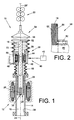
- a spinning station 10 of a centrifuge or pot spinning machine is shown. Centrifugal spinning machines generally have a large number of such spinning stations 10, which are arranged either side by side in a row or in a ring. Each spinning station 10 has a centrifuge spinning device 12, which is shown in FIG. 1 in a schematic longitudinal section.
- the centrifuge spinning device 12 comprises a rotatably mounted, drivable spin pot (centrifuge) 14, in the interior 16 of which a thread guide 18 engages.
- the longitudinal axis 22 of the thread guide 18 coincides with the axis of rotation 24 of the spinning pot 14.
- a roving 26 'stretched in a drafting device 32 can be introduced into the spinning centrifuge 14 by the thread guide 18 and is subsequently spun into a thread 26 under the action of the rotating spinning centrifuge 14.
- the thread 26 emerging from the thread guide opening 36 while forming a thread leg 28 is deposited as a so-called spinning cake 20 on the inner wall 30 of the spinning centrifuge 14.
- a drive device 38 is assigned to the thread guide 18, by means of which an axial relative movement of the thread guide 18 and thus its mouth 36 to the spinning centrifuge 14 can be predetermined.
- the relative movement of the thread guide 18 takes place on the one hand in an oscillating manner, on the other hand the thread guide 18 is constantly shifted somewhat downwards, so that the spinning cake 20 receives a so-called cop winding.
- the drive device 38 is preferably designed as a stepper motor 40 which can be controlled via a control device 42.
- the stepper motor 40 comprises a fixedly mounted stator 44 and a rotor 46 arranged inside the stator.
- the structure and mode of operation of stepper motors 40 are generally known, so that they will not be discussed in more detail in the context of the present description.
- the rotor 46 is designed as a cylinder 48 which has an internal thread 50.
- the internal thread 50 meshes with an external thread 52 of the thread guide 18.
- the meshing threads 50 and 52 lead to an interlocking operative connection between the drive device 38 and the thread guide 18.
- the thread guide 18 itself is in this case by an anti-rotation device 58, which is shown in more detail in FIG. 2 is fixed against rotation.
- the spinning centrifuge 14 is rotated about the axis of rotation 24 at high speed by an electromotive drive device 64.
- roving 26 ' which was previously drawn in a drafting device 32, for example, is fed into the spinning centrifuge 14 via a thread guide 18.
- the roving emerging from the thread guide mouth 36 rests against the inner wall 30 of the spinning centrifuge 14 under the effect of the rotating flow circulating in the spinning centrifuge 14 and is thereby spun into a thread 26.
- the thread 26 forming a circumferential thread leg 28 between the thread guide mouth 36 and the inner wall 30 of the spinning centrifuge 14 is attached to the inner wall 30 of the spinning pot 14 and forms a so-called spinning cake 20 there.
- the thread 26 is placed on the inner wall 30 of the spin pot 14 in the manner of a cop winding. That is, as is known per se, the thread guide 18 is always shifted back and forth by a certain, constant stroke and, at the same time, is continuously shifted somewhat downwards with respect to the rotating spinning pot 14. As a result, the mouth 36 of the thread guide 18 is also displaced relative to the inner wall 30 of the spin pot 14, so that the contact area of the thread leg 28 varies accordingly.
- the above-described thread depositing technique which leads to the formation of a spool cake 20 that can be easily rewound, is predetermined by the control device 42, which takes over a correspondingly manually specified or programmable control of the drive device 38 via a computing unit.
- the stepping motor 40 Corresponding to the actuation of the drive device 38, here the stepping motor 40, its rotor 46, that is to say the cylinder 48, rotates so that it is due to the positive connection between the internal thread 50 of the rotor 46 and the external thread 52 by means of an anti-rotation device 58 against rotation fixed thread guide 18 comes to an axial displacement of the thread guide 18.
- the anti-rotation device 58 can, as indicated in FIG. 2, consist of a longitudinal groove 60 in the area of the external thread 52 of the thread guide 18 and securing element 62.
- the securing element 62 which is fixed, for example, in a rotationally fixed manner on the stator 44 of the stepping motor 40, thereby fits into the longitudinal groove 60.
- the drive device 38 the thread guide 18th almost encompasses, there is only an extremely small amount of space available Arrangement of the drive device 38 necessary. Furthermore, hereby achieved that the actuator, here the rotor 46, directly is operatively connected to the thread guide 18. Hereby the arrangement of intermediate transmission members is not necessary. The driving force can thus be immediate and be initiated precisely. At the same time it is achieved that the drive device 38 the storage of the thread guide 18th takes over. This is practically flying through the Drive device 38 mounted so that on the additional Arrangement of additional bearings or the like can be dispensed with can.
- the centrifuge spinning device 12 is also a cover 54 assigned on the one hand to the drive device 38 and on the other hand at the upper end of the thread guide 18th supports.
- the cover 54 has one flexible cylindrical sheath 56 which the thread guide 18th engages above the drive device 38.
- the wrapping 56 is used, for example, by a so-called bellows educated.
- the cover 54 ensures a seal of the positive connection between the thread guide 18 and the drive device 38. This in particular avoided that during operation of the Centrifuge spinning devices 12 more or less an inevitable fiber fly or the like Impairment of the function of the drive device 38 could cause. Due to the flexibility of the casing 56 can the cover 54 of the lifting movement of the thread guide 18 without more to follow. The seal is thus during everyone Operating phase of the centrifuge spinning device 12 guaranteed.
- the positive connection between the Drive device 38 and the thread guide 18 also in this way be designed so that the drive device 38, for example is designed as a traveling wave motor, the actuator in Friction with the thread guide 18 is. This will also an immediate, that is, in a simple manner direct transmission of the drive energy to the thread guide 18 possible.
Abstract
Description
Die Erfindung betrifft eine Zentrifugenspinnmaschine zum Herstellen von Garn mit den im Oberbegriff des Anspruchs 1 genannten Merkmalen sowie ein Verfahren zum Zentrifugenspinnen von Garn mit den im Oberbegriff des Anspruchs 9 genannten Merkmalen.The invention relates to a centrifuge spinning machine for Manufacture of yarn with the in the preamble of claim 1 mentioned features and a method for Centrifugal spinning of yarn with the in the preamble of Claim 9 mentioned features.
Eine Zentrifugen- oder Topfspinnmaschine und ein Verfahren
der gattungsgemäßen Art sind beispielsweise aus der
DE 42 08 039 A1 und der DE 43 24 039 A1 bekannt.
Derartige Zentrifugenspinnmaschinen umfassen in der Regel
eine Vielzahl von Spinnstellen, die jeweils einen in Rotation
versetzbaren Spinntopf (Zentrifuge) aufweisen. Derartigen
Spinnstellen wird über eine Faserbandverzugseinrichtung,
vorzugsweise einem Streckwerk, Faserband zugeführt, das unter
der Wirkung des um seine Mittelachse rotierenden Spinntopfes
zu einem Faden versponnen wird. Der Faden durchläuft dabei
einen rohrförmigen Fadenführer und tritt an dessen Mündung,
einen Garnschenkel bildend, aus.
Der Faden wird dabei an der Innenwand des Spinntopfes in
Lagen als sogenannter Spinnkuchen abgelegt. Dieses Ablegen
des Spinnkuchens erfolgt, indem eine Relativbewegung zwischen
Fadenführer und Spinntopf in axialer Richtung erzeugt wird.
Diese auch als Changierbewegung bezeichnete Relativbewegung
wird durch eine Antriebseinrichtung für den Fadenführer
und/oder den Spinntopf erzeugt.A centrifuge or pot spinning machine and a method of the generic type are known for example from DE 42 08 039 A1 and DE 43 24 039 A1.
Centrifugal spinning machines of this type generally comprise a large number of spinning stations, each of which has a spin pot (centrifuge) which can be set in rotation. Such spinning stations are fed via a sliver drafting device, preferably a drafting device, sliver which is spun into a thread under the action of the spinning pot rotating about its central axis. The thread passes through a tubular thread guide and exits at its mouth, forming a thread leg.
The thread is deposited in layers on the inner wall of the spinning pot as a so-called spinning cake. This placing of the spinning cake takes place by generating a relative movement between the thread guide and the spinning pot in the axial direction. This relative movement, also referred to as a traversing movement, is generated by a drive device for the thread guide and / or the spinning pot.
Nach Beendigung der Spinnzeit beziehungsweise nach Erreichen einer vorbestimmten Garnmenge im Spinntopf wird das bis zu diesem Zeitpunkt gesponnene Material auf eine auf dem Fadenführer bereitgehaltene Umspulhülse umgewickelt.After the end of the spinning time or after reaching it a predetermined amount of yarn in the spinning pot is up to material spun onto a on the Thread guide held ready wound winding tube.
Aus der DE 41 02 549 A1 ist eine Ringspinneinrichtung
bekannt, mit einer Antriebseinrichtungen zum Erzeugen einer
axialen Relativbewegung zwischen einem auf einem Spinnring
umlaufenden Läufer und einem auf einer Spindelbank
angeordneten Garnträger. Die Antriebseinrichtung umfaßt
beispielsweise einen Hubschlitten, der durch eine
Spindelanordnung verlagerbar ist. Der Antrieb der Spindel
erfolgt vorzugsweise elektromotorisch.
Bei diesen bekannten Antriebseinrichtungen ist nachteilig,
daß eine relativ komplizierte Anordnung vorzusehen ist, die
einen relativ großen Bauraum benötigt. Außerdem erfordert die
frei liegenden Antriebsspindel einen relativ hohen
Wartungsaufwand, da sie, insbesondere in der Faserflug
beaufschlagten Umgebung einer Spinnerei, stark zur Verflusung
neigt.A ring spinning device is known from DE 41 02 549 A1, with a drive device for generating an axial relative movement between a rotor rotating on a spinning ring and a yarn carrier arranged on a spindle bank. The drive device comprises, for example, a lifting carriage which can be displaced by a spindle arrangement. The spindle is preferably driven by an electric motor.
In these known drive devices, it is disadvantageous that a relatively complicated arrangement must be provided, which requires a relatively large amount of space. In addition, the exposed drive spindle requires a relatively high level of maintenance, since, particularly in the fiber flight environment of a spinning mill, it has a strong tendency to flow.
Der Erfindung liegt die Aufgabe zugrunde, eine Vorrichtung und ein Verfahren zu schaffen, mit der/dem in einfacher Weise eine Relativbewegung zwischen einem Fadenführer und einem Spinntopf erzielbar ist.The invention has for its object a device and to create a process with which in a simple manner a relative movement between a thread guide and a Spinning pot is achievable.
Erfindungsgemäß wird diese Aufgabe durch eine Zentrifugenspinnmaschine mit den im Anspruch 1 genannten Merkmalen gelöst.According to the invention, this object is achieved by a Centrifuge spinning machine with those mentioned in claim 1 Features resolved.
Dadurch, daß der im Fadenführer geführte Faden durch die Drehachse des Rotors der Antriebseinrichtung läuft ist eine sehr kompakte Bauweise möglich. The fact that the thread guided in the thread guide through the The axis of rotation of the rotor of the drive device is running very compact design possible.
Das heißt, auf die Anordnung von Zwischenübertragungsgliedern kann verzichtet werden. Neben der Einsparung an Bauraum wird dadurch auch eine erhebliche Montagevereinfachung erzielt.That is, on the arrangement of intermediate transmission links can be dispensed with. In addition to saving on installation space this also considerably simplifies assembly.
Des weiteren wird durch die Verringerung der anzutreibenden Masse erreicht, daß der Energieeinsatz zum Erzeugen einer Relativbewegung zwischen Fadenführer und Spinntopf minimiert ist. Somit wird die Effektivität der gesamten Zentrifugenspinnvorrichtung erhöht.Furthermore, by reducing the amount to be driven Mass achieved that the energy used to generate a Relative movement between thread guide and spinning pot minimized is. Thus, the effectiveness of the whole Centrifuge spinning device increased.
In bevorzugter Ausgestaltung der Erfindung ist vorgesehen, daß die Antriebseinrichtung ein Elektromotor ist, dessen Rotor mit dem Fadenführer unmittelbar wirkverbunden ist, wobei vorzugsweise der Rotor ein Zylinder ist, der den Fadenführer formschlüssig aufnimmt. Hierdurch wird in besonders einfacher Weise eine Übertragung der Antriebsenergie des Elektromotors auf den Fadenführer möglich, da der Rotor des Elektromotors unmittelbar auf den Fadenführer wirkt. Insbesondere wird somit eine sehr genaue Positionierung des Fadenführers möglich, da durch das Fehlen von zwischengeschalteten Übertragungsgliedern Toleranzfehler, Schlupffehler oder dergleichen vermieden werden.In a preferred embodiment of the invention, that the drive device is an electric motor, the Rotor is directly operatively connected to the thread guide, preferably the rotor is a cylinder that the Thread guide takes form-fitting. This will in a particularly simple way of transferring the Driving energy of the electric motor on the thread guide possible because the rotor of the electric motor directly on the Thread guide works. In particular, it becomes a very accurate one Positioning of the thread guide possible because of the absence tolerance errors of intermediate transmission elements, Slip errors or the like can be avoided.
Eine vorteilhafte Ausführungsform ist gegeben, wenn der Rotor
des Elektromotors, wie im Anspruch 4 dargelegt, eine
Innenverzahnung aufweist, die mit einer Außenverzahnung des
Fadenführers kämmt. Hierdurch wird eine sichere,
formschlüssige Verbindung zwischen dem Rotor und dem
Fadenführer erreicht. Über das Außengewinde des Fadenführers
sowie das entsprechende Innengewinde des Rotors kann die
Relativbewegung des Fadenführers bezüglich des Spinntopfes
exakt reproduzierbar eingestellt werden. An advantageous embodiment is given when the rotor of the electric motor, as set out in claim 4, has an internal toothing which meshes with an external toothing of the thread guide. This ensures a safe,
positive connection between the rotor and the thread guide reached. The relative movement of the thread guide with respect to the spinning pot can be set exactly reproducibly via the external thread of the thread guide and the corresponding internal thread of the rotor.
Ferner ist in bevorzugter Ausgestaltung der Erfindung vorgesehen, daß der Elektromotor ein Schrittmotor ist (Anspruch 5). Hierdurch kann durch entsprechende definierte Ansteuerung des Schrittmotors eine exakte Positionierung beziehungsweise exakte axiale Verlagerung des Fadenführers relativ zu dem Spinntopf realisiert werden. Entsprechend der Ansteuerung des Schrittmotors erfolgt eine proportionale Verlagerung des Fadenführers, so daß der am Innenumfang des Spinntopfes abgelegte Spinnkuchen sich durch eine gleichmäßige Fadenlage auszeichnet.Furthermore, in a preferred embodiment of the invention provided that the electric motor is a stepper motor (Claim 5). This can be defined by appropriate Control of the stepper motor an exact positioning or exact axial displacement of the thread guide can be realized relative to the spinning pot. According to the The stepper motor is controlled proportionally Shifting the thread guide so that the on the inner circumference of the Spinnkuchen deposited spinning pot through a uniform thread position.
Erfindungsgemäß wird die Aufgabe ferner durch ein Verfahren mit den im Anspruch 9 genannten Merkmalen gelöst. Dadurch, daß der im Fadenführer geführte Faden durch die Drehachse eines Rotors der Antriebseinrichtung läuft, wobei der Fadenführer zum Erzielen einer Axialbewegung unmittelbar mit einer Antriebskraft beaufschlagt wird, läßt sich eine sehr genaue Relativbewegung des Fadenführers zu dem Spinntopf erzielen. Dieses unmittelbare Angreifen der Antriebskraft an den Fadenführer führt zu einer Minimierung der Positionierungsfehler während der Relativbewegung des Fadenführers. Hierdurch läßt sich die Qualität der erzielten Spinnkuchen in hohem Maße optimieren.According to the invention, the object is further achieved by a method solved with the features mentioned in claim 9. Thereby, that the thread guided in the thread guide through the axis of rotation a rotor of the drive device runs, the Thread guide to achieve an axial movement immediately with a driving force is applied, a very achieve exact relative movement of the thread guide to the spinning pot. This immediate attack on the driving force the thread guide leads to a minimization of the Positioning error during the relative movement of the Thread guide. This allows the quality of the achieved Optimize spin cake to a high degree.
Weitere bevorzugte Ausgestaltungen der Erfindung ergeben sich aus den übrigen, in den Unteransprüchen genannten Merkmalen.Further preferred configurations of the invention result from the other features mentioned in the subclaims.
Die Erfindung wird nachfolgend anhand eines in den Zeichnungen dargestellten Ausführungsbeispiels näher erläutert. The invention is described in the following in the Drawings shown embodiment closer explained.
Es zeigt:
- Fig.1
- eine erfindungsgemäße Zentrifugenspinnstelle in Seitenansicht, teilweise im Schnitt,
- Fig.2
- die Verdrehsicherung für den Fadenführer in einem größerern Maßstab.
- Fig. 1
- a centrifuge spinning station according to the invention in side view, partly in section,
- Fig. 2
- the twist lock for the thread guide on a larger scale.
In der Figur ist eine Spinnstelle 10 einer Zentrifugen- oder
Topfspinnmaschine gezeigt. Zentrifugenspinnmaschinen besitzen
in der Regel eine Vielzahl derartiger Spinnstellen 10, die
entweder reihenförmig oder ringförmig nebeneinanderliegend
angeordnet sind. Jede Spinnstelle 10 besitzt eine
Zentrifugenspinnvorrichtung 12, die in der Figur 1 in einem
schematischen Längsschnitt dargestellt ist.
Die Zentrifugenspinnvorrichtung 12 umfaßt einen rotierbar
gelagerten, antreibbaren Spinntopf (Zentrifuge) 14, in dessen
Innenraum 16 ein Fadenführer 18 eingreift. Die Längsachse 22
des Fadenführers 18 fällt dabei mit der Drehachse 24 des
Spinntopfs 14 zusammen.
Durch den Fadenführer 18 kann ein in einem Streckwerk 32
verstrecktes Vorgarn 26' in die Spinnzentrifuge 14 eingeführt
werden, das anschließend unter der Wirkung der rotierenden
Spinnzentrifuge 14 zu einem Faden 26 versponnen wird. Der
unter Ausbildung eines Fadenschenkels 28 aus der
Fadenführermündung 36 austretende Faden 26 wird dabei als
sogenannter Spinnkuchen 20 an der Innenwandung 30 der
Spinnzentrifuge 14 abgelegt.In the figure, a
The
A roving 26 'stretched in a
Dem Fadenführer 18 ist eine Antriebseinrichtung 38
zugeordnet, mittels der eine axiale Relativbewegung des
Fadenführers 18 und somit dessen Mündung 36 zur
Spinnzentrifuge 14 vorgebbar ist. Die Relativbewegung des
Fadenführers 18 erfolgt dabei einerseits changierend,
anderseits wird der Fadenführer 18 ständig etwas nach unten
verlagert, so daß der Spinnkuchen 20 eine sogenannte
Kopswicklung erhält.
Die Antriebseinrichtung 38 ist vorzugsweise als Schrittmotor
40 ausgebildet, der über eine Steuereinrichtung 42
ansteuerbar ist. Der Schrittmotor 40 umfaßt einen ortsfest
gelagerten Stator 44 sowie einen innerhalb des Stators
angeordneten Rotor 46. Aufbau und Wirkungsweise von
Schrittmotoren 40 sind allgemein bekannt, so daß im Rahmen
der vorliegenden Beschreibung hierauf nicht näher eingegangen
werden soll.
Der Rotor 46 ist als Zylinder 48 ausgebildet, der ein
Innengewinde 50 besitzt. Das Innengewinde 50 kämmt mit einem
Außengewinde 52 des Fadenführers 18. Die kämmenden Gewinde 50
und 52 führen zu einer formschlüssigen Wirkverbindung
zwischen der Antriebseinrichtung 38 und dem Fadenführer 18.
Der Fadenführer 18 selber ist hierbei durch eine
Verdrehsicherung 58, die in Fig. 2 näher dargestellt ist,
gegen Rotation festgelegt.A
The
The
Während des Betriebes der Spinnstelle 10 wird die
Spinnzentrifuge 14 durch eine elektromotorische
Antriebseinrichtung 64 mit hoher Drehzahl um die Drehachse 24
rotiert. Außerdem wird über einen Fadenführer 18 Vorgarn 26',
das vorher z.B. in einem Streckwerk 32 verstreckt wurde, in
die Spinnzentrifuge 14 eingespeist. Das aus der
Fadenführermündung 36 austretende Vorgarn legt sich unter der
Wirkung der in der Spinnzentrifuge 14 umlaufenden
Rotationsströmung an die Innenwandung 30 der Spinnzentrifuge
14 an und wird dabei zu einem Faden 26 versponnen. Der
zwischen der Fadenführermündung 36 und der Innenwandung 30
der Spinnzentrifuge 14 einen umlaufenden Fadenschenkel 28
bildende Faden 26 lagert sich an der Innenwandung 30 des
Spinntopfes 14 an und bildet dort einen sogenannten
Spinnkuchen 20.
Zur Ausbildung eines möglichst gut umspulbaren Spinnkuchens
20, wird der Faden 26 dabei nach Art einer Kopswicklung auf
der Innenwandung 30 des Spinntopf 14 abgelegt.
Das heißt, der Fadenführer 18 wird, wie an sich bekannt,
stets um einen bestimmten, gleichbleibenden Hub hin- und
herchangiert und dabei gleichzeitig bezüglich des rotierenden
Spinntopfes 14 fortlaufend etwas nach unten verlagert.
Hierdurch wird auch die Mündung 36 des Fadenführers 18
relativ zur Innenwandung 30 des Spinntopfes 14 verlagert, so
daß der Anlagebereich des Fadenschenkels 28 entsprechend
variiert. Die vorbeschriebene Fadenablagetechnik, die zur
Ausbildung eines gut umspulbaren Spinnkuchens 20 führt, wird
über die Steuereinrichtung 42 vorgegeben, die eine
entsprechend manuell vorgebbare oder über eine Recheneinheit
programmierbare Ansteuerung der Antriebseinrichtung 38
übernimmt.During the operation of the
To form a
That is, as is known per se, the
As a result, the
Entsprechend der Ansteuerung der Antriebseinrichtung 38, hier
des Schrittmotors 40, erfolgt eine Rotation seines Rotors 46,
das heißt des Zylinders 48, so daß es aufgrund der
formschlüssigen Verbindung zwischen dem Innengewinde 50 des
Rotors 46 und dem Außengewinde 52 des durch eine
Verdrehsicherung 58 gegen Rotation festgelegten Fadenführers
18 zu einer axialen Verlagerung des Fadenführes 18 kommt.
Die Verdrehsicherung 58 kann, wie in Fig.2 angedeutet, aus
einer Längsnut 60 im Bereich des Außengewindes 52 des
Fadenführers 18 und Sicherungselement 62 bestehen. Das z.B.
drehfest am Stator 44 des Schrittmotors 40 festgelegte
Sicherungselement 62 faßt dabei in die Längsnut 60.Corresponding to the actuation of the
The
Dadurch, daß die Antriebseinrichtung 38 den Fadenführer 18
quasi umgreift, ist nur ein äußerst geringer Bauraum zur
Anordnung der Antriebseinrichtung 38 notwendig. Ferner wird
hierdurch erreicht, daß der Aktor, hier der Rotor 46, unmittelbar
mit dem Fadenführer 18 wirkverbunden ist. Hierdurch
wird die Anordnung von Zwischenübertragungsgliedern nicht
notwendig. Die Antriebskraft kann somit unmittelbar und
präzise eingeleitet werden. Gleichzeitig wird erreicht, daß
die Antriebseinrichtung 38 die Lagerung des Fadenführers 18
übernimmt. Dieser ist quasi fliegend durch die
Antriebseinrichtung 38 gelagert, so daß auf die zusätzliche
Anordnung weiterer Lager oder dergleichen verzichtet werden
kann.Characterized in that the
Der Zentrifugenspinnvorrichtung 12 ist ferner eine Abdeckung
54 zugeordnet, die sich einerseits an der Antriebseinrichtung
38 und andererseits am oberen Ende des Fadenführers 18
abstützt. Die Abdeckung 54 besitzt eine im wesentlichen
flexible zylindrische Umhüllung 56, die den Fadenführer 18
oberhalb der Antriebseinrichtung 38 umgreift. Die Umhüllung
56 wird beispielsweise von einem sogenannten Faltenbalg
gebildet. The
Die Abdeckung 54 gewährleistet eine Abdichtung der
formschlüssigen Verbindung zwischen dem Fadenführer 18 und
der Antriebseinrichtung 38. Hierdurch wird insbesondere
vermieden, daß während des Betriebes der
Zentrifugenspinnvorrichtungen 12 mehr oder weniger
zwangsläufig anfallender Faserflug oder dergleichen eine
Beeinträchtigung der Funktion der Antriebseinrichtung 38
bewirken könnte. Durch die Flexibilität der Umhüllung 56 kann
die Abdeckung 54 der Hubbewegung des Fadenführers 18 ohne
weiteres folgen. Die Abdichtung ist somit während jeder
Betriebsphase der Zentrifugenspinnvorrichtung 12
gewährleistet.The
Nach weiteren, nicht dargestellten Ausführungsbeispielen kann
die kraftschlüssige Verbindung zwischen der
Antriebseinrichtung 38 und dem Fadenführer 18 auch derart
gestaltet sein, daß die Antriebseinrichtung 38 beispielsweise
als Wanderwellenmotor ausgebildet ist, deren Aktor in
Reibschluß mit dem Fadenführer 18 steht. Hierdurch wird
ebenfalls in einfacher Weise eine unmittelbare, das heißt
direkte Übertragung der Antriebsenergie auf den Fadenführer
18 möglich.According to further embodiments, not shown
the positive connection between the
Claims (9)
dadurch gekennzeichnet,
daß der im Fadenführer (18) geführte Faden (26) durch die Drehachse eines Rotors 46) der Antriebseinrichtung (38) läuft.Centrifugal spinning machine with at least one spinning station, each of which has a spinning pot which can be set in rotation, a thread guide which can be fed with roving, and a drive device for generating an axial relative movement between the thread guide and the spinning pot, a thread emerging from the thread guide being depositable as a spinning cake on the inner wall of the spinning pot,
characterized,
that the thread (26) guided in the thread guide (18) runs through the axis of rotation of a rotor 46) of the drive device (38).
Applications Claiming Priority (2)
| Application Number | Priority Date | Filing Date | Title |
|---|---|---|---|
| DE19905859 | 1999-02-12 | ||
| DE19905859A DE19905859A1 (en) | 1999-02-12 | 1999-02-12 | Centrifugal spinning machine and method for centrifugal spinning |
Publications (2)
| Publication Number | Publication Date |
|---|---|
| EP1028181A1 true EP1028181A1 (en) | 2000-08-16 |
| EP1028181B1 EP1028181B1 (en) | 2003-06-25 |
Family
ID=7897280
Family Applications (1)
| Application Number | Title | Priority Date | Filing Date |
|---|---|---|---|
| EP00100169A Expired - Lifetime EP1028181B1 (en) | 1999-02-12 | 2000-01-11 | Pot spinning machine and method for centrifugal spinning |
Country Status (7)
| Country | Link |
|---|---|
| US (1) | US6240715B1 (en) |
| EP (1) | EP1028181B1 (en) |
| JP (1) | JP2000234221A (en) |
| CN (1) | CN1263905C (en) |
| AT (1) | ATE243785T1 (en) |
| DE (2) | DE19905859A1 (en) |
| TR (1) | TR200000389A3 (en) |
Cited By (1)
| Publication number | Priority date | Publication date | Assignee | Title |
|---|---|---|---|---|
| US7172399B2 (en) | 2002-12-13 | 2007-02-06 | Saurer Gmbh & Co. Kg | Spin beam |
Families Citing this family (1)
| Publication number | Priority date | Publication date | Assignee | Title |
|---|---|---|---|---|
| JP6402891B2 (en) * | 2014-03-06 | 2018-10-10 | Toto株式会社 | Remote control device |
Citations (4)
| Publication number | Priority date | Publication date | Assignee | Title |
|---|---|---|---|---|
| CH323562A (en) * | 1954-09-08 | 1957-08-15 | Spinnerei Karl Marx Veb | Linearly guided traversing device for centrifugal rayon spinning machines |
| US3314223A (en) * | 1962-10-30 | 1967-04-18 | Bobkowicz Emilian | Apparatus for yarn production |
| EP0498171A2 (en) * | 1991-02-08 | 1992-08-12 | W. SCHLAFHORST AG & CO. | Method and apparatus for producing a yarn by the centrifugal spinning method |
| DE4236379A1 (en) * | 1992-10-28 | 1994-05-05 | Schlafhorst & Co W | Centrifugal spinning machine - has reserve pneumatic mechanism to extract yarn from pot during power failure |
Family Cites Families (4)
| Publication number | Priority date | Publication date | Assignee | Title |
|---|---|---|---|---|
| DE4102549A1 (en) | 1991-01-29 | 1992-07-30 | Schlafhorst & Co W | Spinning frame - has separate drives for traverse winding motion and lifter mechanism |
| DE4208039C2 (en) | 1992-03-13 | 2002-01-17 | Schlafhorst & Co W | Pot spinning device |
| DE4324039A1 (en) | 1993-07-17 | 1995-01-19 | Schlafhorst & Co W | Transport system on a can-spinning machine |
| DE19548675A1 (en) * | 1995-12-23 | 1997-06-26 | Csm Gmbh | Spinning tube drive for centrifugal or vacuum spinner |
-
1999
- 1999-02-12 DE DE19905859A patent/DE19905859A1/en not_active Withdrawn
-
2000
- 2000-01-11 DE DE50002624T patent/DE50002624D1/en not_active Expired - Fee Related
- 2000-01-11 AT AT00100169T patent/ATE243785T1/en not_active IP Right Cessation
- 2000-01-11 EP EP00100169A patent/EP1028181B1/en not_active Expired - Lifetime
- 2000-02-07 US US09/499,432 patent/US6240715B1/en not_active Expired - Fee Related
- 2000-02-09 JP JP2000032215A patent/JP2000234221A/en not_active Withdrawn
- 2000-02-10 TR TR2000/00389A patent/TR200000389A3/en unknown
- 2000-02-12 CN CNB001023136A patent/CN1263905C/en not_active Expired - Fee Related
Patent Citations (4)
| Publication number | Priority date | Publication date | Assignee | Title |
|---|---|---|---|---|
| CH323562A (en) * | 1954-09-08 | 1957-08-15 | Spinnerei Karl Marx Veb | Linearly guided traversing device for centrifugal rayon spinning machines |
| US3314223A (en) * | 1962-10-30 | 1967-04-18 | Bobkowicz Emilian | Apparatus for yarn production |
| EP0498171A2 (en) * | 1991-02-08 | 1992-08-12 | W. SCHLAFHORST AG & CO. | Method and apparatus for producing a yarn by the centrifugal spinning method |
| DE4236379A1 (en) * | 1992-10-28 | 1994-05-05 | Schlafhorst & Co W | Centrifugal spinning machine - has reserve pneumatic mechanism to extract yarn from pot during power failure |
Cited By (1)
| Publication number | Priority date | Publication date | Assignee | Title |
|---|---|---|---|---|
| US7172399B2 (en) | 2002-12-13 | 2007-02-06 | Saurer Gmbh & Co. Kg | Spin beam |
Also Published As
| Publication number | Publication date |
|---|---|
| EP1028181B1 (en) | 2003-06-25 |
| CN1263905C (en) | 2006-07-12 |
| TR200000389A2 (en) | 2000-09-21 |
| DE50002624D1 (en) | 2003-07-31 |
| ATE243785T1 (en) | 2003-07-15 |
| DE19905859A1 (en) | 2000-08-17 |
| TR200000389A3 (en) | 2000-09-21 |
| JP2000234221A (en) | 2000-08-29 |
| US6240715B1 (en) | 2001-06-05 |
| CN1263174A (en) | 2000-08-16 |
Similar Documents
| Publication | Publication Date | Title |
|---|---|---|
| EP1749906B1 (en) | Piecing arrangement for a rotor type open-end spinning machine | |
| EP0644281B1 (en) | Procedure and device for producing a twisted yarn | |
| DE2215444C2 (en) | Device for winding coils axially retractable in a stator of a dynamo-electric machine | |
| EP2733241A1 (en) | Two to one spinning machine | |
| EP0165428A2 (en) | Textile machine with several winding units, whereby a yarn is wound on a conical spool at a constant speed | |
| CH688826A5 (en) | Apparatus for winding of packages. | |
| DE4343933A1 (en) | Electric drive for appts. with several, coaxial, driven shafts | |
| CH694853A5 (en) | Wire electric discharge machining apparatus comprising wire bobbin on which wire electrode is wound | |
| CH693380A5 (en) | Method and device for winding a continuously advancing yarn. | |
| EP0701014B1 (en) | Procedure for piecing yarn in a device, for producing a twisted yarn in an integrated spinning and twisting process, as well as a device to carry out the procedure | |
| DE19915529A1 (en) | Winder for conical cross wound bobbins, has a sensor to register the bobbin diameter and a sensor to monitor the position and/or movement direction of the yarn guide to set the yarn store in the yarn feed system | |
| EP1028181B1 (en) | Pot spinning machine and method for centrifugal spinning | |
| EP0696656B1 (en) | Procedure and device for producing a twisted yarn | |
| DE4336109C2 (en) | Method and device for making a thread | |
| EP0165444B1 (en) | Drive for a waxing device and method for driving such a device | |
| EP1126058A2 (en) | Device for driving rotating components in an open-end spinning machine | |
| EP0799787B1 (en) | Winding machine | |
| EP0697476B1 (en) | Procedure for producing a twisted yarn in an integrated spinning and twisting process using the two-for-one principle, as well as a device to carry out the procedure | |
| DE4427876C1 (en) | A combined open end rotor spinning and twist unit producing ply yarn | |
| EP0732441A2 (en) | Cable-making machine | |
| EP0468191A1 (en) | Method of spinning fibres into yarn and spinning machine for carrying out the method | |
| DE19746819A1 (en) | Control of under-winding of waste on self-cleaning ring spindle | |
| DE3347739A1 (en) | Stranding machine | |
| DE3810876C2 (en) | ||
| EP3611295A1 (en) | Yarn accumulating device for a spinning or winding machine |
Legal Events
| Date | Code | Title | Description |
|---|---|---|---|
| PUAI | Public reference made under article 153(3) epc to a published international application that has entered the european phase |
Free format text: ORIGINAL CODE: 0009012 |
|
| AK | Designated contracting states |
Kind code of ref document: A1 Designated state(s): AT CH DE GB IT LI |
|
| AX | Request for extension of the european patent |
Free format text: AL;LT;LV;MK;RO;SI |
|
| 17P | Request for examination filed |
Effective date: 20010216 |
|
| AKX | Designation fees paid |
Free format text: AT CH DE GB IT LI |
|
| GRAH | Despatch of communication of intention to grant a patent |
Free format text: ORIGINAL CODE: EPIDOS IGRA |
|
| GRAH | Despatch of communication of intention to grant a patent |
Free format text: ORIGINAL CODE: EPIDOS IGRA |
|
| GRAA | (expected) grant |
Free format text: ORIGINAL CODE: 0009210 |
|
| RIN1 | Information on inventor provided before grant (corrected) |
Inventor name: SOPALA, MICHAEL Inventor name: KOLTZE, KARL Inventor name: BRUSS, KARL-HEINZ |
|
| AK | Designated contracting states |
Designated state(s): AT CH DE GB IT LI |
|
| REG | Reference to a national code |
Ref country code: GB Ref legal event code: FG4D Free format text: NOT ENGLISH |
|
| REG | Reference to a national code |
Ref country code: CH Ref legal event code: EP |
|
| GBT | Gb: translation of ep patent filed (gb section 77(6)(a)/1977) | ||
| REF | Corresponds to: |
Ref document number: 50002624 Country of ref document: DE Date of ref document: 20030731 Kind code of ref document: P |
|
| RAP2 | Party data changed (patent owner data changed or rights of a patent transferred) |
Owner name: SAURER GMBH & CO. KG |
|
| PG25 | Lapsed in a contracting state [announced via postgrant information from national office to epo] |
Ref country code: GB Free format text: LAPSE BECAUSE OF NON-PAYMENT OF DUE FEES Effective date: 20040111 Ref country code: AT Free format text: LAPSE BECAUSE OF NON-PAYMENT OF DUE FEES Effective date: 20040111 |
|
| PLBE | No opposition filed within time limit |
Free format text: ORIGINAL CODE: 0009261 |
|
| STAA | Information on the status of an ep patent application or granted ep patent |
Free format text: STATUS: NO OPPOSITION FILED WITHIN TIME LIMIT |
|
| 26N | No opposition filed |
Effective date: 20040326 |
|
| GBPC | Gb: european patent ceased through non-payment of renewal fee |
Effective date: 20040111 |
|
| PG25 | Lapsed in a contracting state [announced via postgrant information from national office to epo] |
Ref country code: IT Free format text: LAPSE BECAUSE OF NON-PAYMENT OF DUE FEES;WARNING: LAPSES OF ITALIAN PATENTS WITH EFFECTIVE DATE BEFORE 2007 MAY HAVE OCCURRED AT ANY TIME BEFORE 2007. THE CORRECT EFFECTIVE DATE MAY BE DIFFERENT FROM THE ONE RECORDED. Effective date: 20050111 |
|
| PGFP | Annual fee paid to national office [announced via postgrant information from national office to epo] |
Ref country code: DE Payment date: 20070102 Year of fee payment: 8 |
|
| PGFP | Annual fee paid to national office [announced via postgrant information from national office to epo] |
Ref country code: CH Payment date: 20070104 Year of fee payment: 8 |
|
| REG | Reference to a national code |
Ref country code: CH Ref legal event code: PL |
|
| PG25 | Lapsed in a contracting state [announced via postgrant information from national office to epo] |
Ref country code: LI Free format text: LAPSE BECAUSE OF NON-PAYMENT OF DUE FEES Effective date: 20080131 Ref country code: DE Free format text: LAPSE BECAUSE OF NON-PAYMENT OF DUE FEES Effective date: 20080801 Ref country code: CH Free format text: LAPSE BECAUSE OF NON-PAYMENT OF DUE FEES Effective date: 20080131 |