EP1027196B1 - Modified slot extrusion die - Google Patents
Modified slot extrusion die Download PDFInfo
- Publication number
- EP1027196B1 EP1027196B1 EP98949521A EP98949521A EP1027196B1 EP 1027196 B1 EP1027196 B1 EP 1027196B1 EP 98949521 A EP98949521 A EP 98949521A EP 98949521 A EP98949521 A EP 98949521A EP 1027196 B1 EP1027196 B1 EP 1027196B1
- Authority
- EP
- European Patent Office
- Prior art keywords
- die
- discharge
- accordance
- flow
- slots
- Prior art date
- Legal status (The legal status is an assumption and is not a legal conclusion. Google has not performed a legal analysis and makes no representation as to the accuracy of the status listed.)
- Expired - Lifetime
Links
Images

Classifications
-
- B—PERFORMING OPERATIONS; TRANSPORTING
- B28—WORKING CEMENT, CLAY, OR STONE
- B28B—SHAPING CLAY OR OTHER CERAMIC COMPOSITIONS; SHAPING SLAG; SHAPING MIXTURES CONTAINING CEMENTITIOUS MATERIAL, e.g. PLASTER
- B28B3/00—Producing shaped articles from the material by using presses; Presses specially adapted therefor
- B28B3/20—Producing shaped articles from the material by using presses; Presses specially adapted therefor wherein the material is extruded
- B28B3/26—Extrusion dies
- B28B3/269—For multi-channeled structures, e.g. honeycomb structures
-
- B—PERFORMING OPERATIONS; TRANSPORTING
- B28—WORKING CEMENT, CLAY, OR STONE
- B28B—SHAPING CLAY OR OTHER CERAMIC COMPOSITIONS; SHAPING SLAG; SHAPING MIXTURES CONTAINING CEMENTITIOUS MATERIAL, e.g. PLASTER
- B28B3/00—Producing shaped articles from the material by using presses; Presses specially adapted therefor
- B28B3/20—Producing shaped articles from the material by using presses; Presses specially adapted therefor wherein the material is extruded
- B28B3/26—Extrusion dies
-
- B—PERFORMING OPERATIONS; TRANSPORTING
- B29—WORKING OF PLASTICS; WORKING OF SUBSTANCES IN A PLASTIC STATE IN GENERAL
- B29C—SHAPING OR JOINING OF PLASTICS; SHAPING OF MATERIAL IN A PLASTIC STATE, NOT OTHERWISE PROVIDED FOR; AFTER-TREATMENT OF THE SHAPED PRODUCTS, e.g. REPAIRING
- B29C48/00—Extrusion moulding, i.e. expressing the moulding material through a die or nozzle which imparts the desired form; Apparatus therefor
- B29C48/03—Extrusion moulding, i.e. expressing the moulding material through a die or nozzle which imparts the desired form; Apparatus therefor characterised by the shape of the extruded material at extrusion
- B29C48/09—Articles with cross-sections having partially or fully enclosed cavities, e.g. pipes or channels
- B29C48/11—Articles with cross-sections having partially or fully enclosed cavities, e.g. pipes or channels comprising two or more partially or fully enclosed cavities, e.g. honeycomb-shaped
-
- B—PERFORMING OPERATIONS; TRANSPORTING
- B29—WORKING OF PLASTICS; WORKING OF SUBSTANCES IN A PLASTIC STATE IN GENERAL
- B29C—SHAPING OR JOINING OF PLASTICS; SHAPING OF MATERIAL IN A PLASTIC STATE, NOT OTHERWISE PROVIDED FOR; AFTER-TREATMENT OF THE SHAPED PRODUCTS, e.g. REPAIRING
- B29C48/00—Extrusion moulding, i.e. expressing the moulding material through a die or nozzle which imparts the desired form; Apparatus therefor
- B29C48/03—Extrusion moulding, i.e. expressing the moulding material through a die or nozzle which imparts the desired form; Apparatus therefor characterised by the shape of the extruded material at extrusion
- B29C48/12—Articles with an irregular circumference when viewed in cross-section, e.g. window profiles
-
- B—PERFORMING OPERATIONS; TRANSPORTING
- B29—WORKING OF PLASTICS; WORKING OF SUBSTANCES IN A PLASTIC STATE IN GENERAL
- B29L—INDEXING SCHEME ASSOCIATED WITH SUBCLASS B29C, RELATING TO PARTICULAR ARTICLES
- B29L2031/00—Other particular articles
- B29L2031/60—Multitubular or multicompartmented articles, e.g. honeycomb
Definitions
- the present invention relates to extrusion dies for the continuous extrusion of fine structures from plasticized materials, and more particularly to honeycomb extrusion dies comprising improved discharge slot designs imparting more uniform and stable extrusion characteristics to the dies.
- inorganic honeycomb structures from plasticized powder batches comprising inorganic powders dispersed in appropriate binders is well known.
- U.S. Patents Nos. 3, 790, 654 , 3, 885, 977 , and 3,905,743 describe dies, processes and compositions for such manufacture, while U.S. Patents No. 4,992, 233 and 5,011,529 describe honeycombs of similar cellular structure extruded from batches incorporating metal powders.
- extrusion dies for the production of ceramic honeycombs by these methods requires extremely precise machining.
- the inlet or supply face of the die is provided with multiple apertures or feed holes through which the plasticized batch material to be extruded is forced under high pressure.
- the opposing or discharge face of the die is provided with a criss-crossing array of finely machined discharge slots, these slots being cut into the discharge section of the die and intersecting the feed hole array. It is these discharge slots which shape the plasticized batch supplied to the bases of the slots by the feed holes into the interconnecting wall structure of an extruded honeycomb.
- pins The islands of material between the intersecting discharge slots, which form the actual discharge face of the die, are sometimes referred to as "pins", since they appear as free-standing metal posts extending outwardly from the die interior and are attached to the die body only at their bases.
- the shapes of these pins define the shapes of the honeycomb channels formed by the extruding plasticized batch.
- the feed hole array can be formed by mechanical drilling and the discharge slots by sawing.
- the die is to be formed of harder, slower wearing materials such as stainless steels, electrochemical machining and electrical discharge machining are more widely used.
- the feed hole apertures are formed through a controlled deplating (dissolution) of the electrically conductive steel workpiece.
- An electrolytic cell is formed wherein the drill comprises the negatively charged electrode (cathode), the workpiece comprises the positively charged electrode (anode), and the electrolyte is a flowing electrically conductive fluid.
- the discharge slots are formed through an electrical discharge maintained between a long, thin, traveling electrode wire and the metal die preform.
- Slot lengths formed by wire EDM in these dies are generally greater than about 88.9 mm (3-1/2 inches), with slot depths of 2.5 mm (0.1 inches) or more and slot widths of 0.3 mm (0.012 inches) or less.
- EDM is well suited for the shaping of thin slots with parallel sidewalls in these dies.
- the slots are typically substantially free of burrs and have a relatively smooth and consistent surface finish.
- Reference to U.S. Patents Nos. 2, 526, 423 , 4,205,213 , 4,233,486 , 4,403,131 and 4,527,035 may be made for further descriptions of EDM processing.
- Honeycomb extrusion die designs incorporating discharge slot extensions to act as feed reservoirs for the batch material to be extruded are disclosed in US-A-5 487 863 , and EP-A-0776743 .
- the slots are of dual width design, and a multilayer transition section is disposed between the feed section and the discharge section.
- US-A-4235583 discloses designs with feedhole extensions into the bases of the discharge slots, also designed to improve lateral batch flow, while EP-A-0 228 258 describes extrusion dies for similar applications incorporating feed hole shape modifications designed to improve the uniformity of batch flow through the dies.
- Each of US-A-5487863 , EP-A-0776743 , US-A-4235583 and EP-A-0228258 describes a honeycomb extrusion die according to the preamble of claim 1.
- the present invention provides honeycomb extrusion die designs offering significant improvements in flow uniformity and stability. These improvements result from the use of modified slot designs which appear to "mask" smaller finish irregularities and thereby remove many of the harmful effects of small variations in slot geometry and surface finish, variations which cannot be economically eliminated by conventional machining methods.
- the modified slot designs of the invention are produced by impressing a "macro" geometric feature on the side surfaces of the pins forming the discharge slots. Although the presence of this feature on selected pin side surfaces can somewhat increase the flow impedance of the dies, such increases are more than offset by the very substantial reductions in extrudate flow front variations. These reductions in turn substantially reduce product defects such as swollen or undulating web (channel wall) surfaces in the honeycomb products caused by flow variations through the dies. Still other benefits of the modified slot design are more fully described below.
- the invention includes.a "modified slot" honeycomb extrusion die.
- This die which in other respects may be entirely conventional, comprises a die body incorporating an inlet face, a discharge face opposite the inlet face, and a plurality of feed holes extending from the inlet face into the body.
- the die further includes an intersecting array of discharge slots extending into the die body from the discharge face, these slots being formed or bounded by the side surfaces of the plurality of pins filling inter-slot spaces on the discharge face of the die.
- the slots and adjacent pins extend inwardly into the die body from the discharge face so that the bases of the slots connect with the feed holes in a manner permitting fluid flow from the feed holes into the slots.
- one or more side surfaces of at least some of the pins incorporate at least one geometrically designed flow-modifying surface discontinuity, i.e., a macroscopic discontinuity in surface flatness on one or more sides of the pins.
- a geometrically designed flow-modifying surface discontinuity i.e., a macroscopic discontinuity in surface flatness on one or more sides of the pins.
- the "macro" geometric pin features of the invention typically have sizes of the same order of magnitude as the widths of the discharge slots themselves.
- the geometric surface discontinuity consists of a surface recess or a surface protrusion. The discontinuity is of a size sufficient to modify the flow of extrudable material through the slots.
- the invention offers an improved extrusion process which employs the modified flow characteristics of the die of the invention to form extruded honeycombs with fewer shape defects attributable to flow variations imparted by the die.
- the batch material is first forced into feed holes in an inlet face of the honeycomb extrusion die, and is then caused to flow through the feed holes and out of the die through a slotted discharge section.
- the discharge section comprises an intersecting array of discharge slots formed in the discharge face of the die.
- the discharge slots in the discharge section border on and define an array of pins terminating at the discharge face, the side surfaces of these pins constituting the forming surfaces which shape the plasticized batch material into the honeycomb as that material exits the die.
- the flow of material through these discharge slots is altered as it traverses one or more geometrically designed flow-modifying surface discontinuities provided on one or more side surfaces of at least some of the pins.
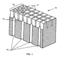
- Fig. 1 is a schematic perspective view in partial cross-section of a section of a conventional honeycomb extrusion die of the kind employed in the art for the extrusion of ceramic honeycombs.
- extrusion die 10 comprises feed holes 13 extending upwardly from a die inlet face (not shown) by means of which extrudable batch material is conveyed to feed hole/slot intersections 15, and from there into discharge slots 17.
- Discharge slots 17 then convey the batch material upwardly to discharge face 18 of the extrusion die where it exits the die in the configuration of a honeycomb.
- discharge slots 17 are bounded or formed by the side surfaces of pins 19, the latter being formed as the discharge slots are formed. It is the side surfaces of pins 19 which form the walls of the slots and thus the walls of the honeycomb shapes as the batch material is extruded from the die.
- Fig. 2 of the drawing is a schematic perspective view in partial cross-section of a section of a honeycomb extrusion die provided in accordance with the invention.
- extrusion die 10a again comprises feed holes 13 extending upwardly from the die inlet face and which intersect with discharge slots 17 at the base of the discharge section of the die.
- pins 19a bounding discharge slots 17 incorporate side surfaces, 20 which include geometrically designed surface features 21 for modifying the flow of extrudable material past the die.
- Features 21, in this embodiment are grooves or recesses formed in selected side surfaces of pins 20 which act to introduce shear within the extrudable material, thereby somewhat impeding its flow past the pin surfaces incorporating the recess.
- a "geometrically designed" feature is a feature of a predetermined size and shape impressed upon a pin or slot surface of the honeycomb extrusion die. This is in contradistinction to random surface variations of the kind typically present in the slot regions of extrusion dies machined in accordance with prior practice.
- the most effective features tried appear to be those having a maximum dimension of length (parallel to the extrusion direction) or height/depth (perpendicular to the pin surface) which is roughly the same as, or'within one order of magnitude of, the slot width dimension of the extrusion die, the latter dimension ordinarily falling within the range of about 0.025-0.25 mm (0.001-0.010 inches).
- the length of a typical feature measured parallel to the direction of extrusion will most preferably be in the range of 100-200% of the slot width.
- the determination of optimum feature depth may involve a consideration of the maximum particle size present in the powder mixture making up the plasticized powder batch to be extruded.
- the preferred recess depths will usually be adequate to accept and retain even the largest powder particles present in the batch; for typical ceramic batches, recesses in the 0.051 to 0.127 mm (0.002-0.005 inches) will generally be adequate for this purpose.
- larger and/or smaller surface features may have equal or superior utility for applications where other batch rheologies and/or compositions are required to be extruded.
- Recess'designs such as shown in Fig. 2 of the drawing have an advantage over protrusion designs in that the flow modifications which develop are thought to arise from batch-to-batch drag effects; batch material trapped in the recesses tends to impede or retard the flow of adjacent batch material traversing the slots. Drag effects of this type will tend to remain relatively constant over the life of the extrusion die, whereas geometric features which protrude from pin side surfaces will tend to be altered by the abrasive wear effects typically seen in these dies. In the latter case the performance of the feature is more likely to change over time.
- a further and somewhat unexpected aspect of the performance of the feature arrangement of Fig. 2 is that the inclusion of grooves only on one (e.g., horizontal) set of pin surfaces, and not on the transverse or vertical pin surfaces, does not appear to adversely affect honeycomb integrity or cell wall geometry in any way.
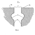
- Fig. 3 shows a partial schematic cross-sectional view of the pin region of an extrusion die taken through two adjacent pins 19a in a plane transverse to the direction of a discharge slot 17.
- teardrop-shaped entities 21 are cut into opposing side surfaces 20 of the selected pair of pins, i.e., on both sidewalls of the selected slot.
- the designation of teardrop shape applies to the groove cross-section when viewed in a plane parallel to the flow of material and perpendicular to the pin side surface. Machining of the feature involves forming the teardrop shape in mirror image about the cénterline of the slot.
- a teardrop-shaped recess or depression of this type can readily be formed by wire EDM cutting in dies wherein the slots are pre-formed.
- pins having this particular feature design can be set upon a pre-drilled die base using procedures know in the art.
- the teardrop feature shape has the advantage of allowing easy fill at the start of extrusion when carried out in the direction of arrow D in Fig. 3 . At the same time, this feature shape is able to maintain a static batch pocket for relatively constant shear during the course of the ensuing extrusion.
- the depth location of the features within the discharge slots does not appear to have a large effect on feature performance.
- Trials with recess features of the type shown in Fig 3 but located at 5 times, 9.5 times and 14 times the slot width dimension away from the discharge face of the die, appear to offer approximately equivalent extrusion performance. Therefore, the precise location of the features within the slots may be selected based on other considerations, such as pin wear rate, the latter tending to favor feature positions closer to the discharge face than to the bases of the pins.
- EDM machining constitutes an effective way to form grooves of controlled size and shape in pin side surfaces along the entire lengths of selected slots.
- a specific illustration of .such a machining technique is presented in the following Example, which is intended to be illustrative of the invention rather than limiting.
- a steel honeycomb extrusion die having a conventional configuration such as shown in Fig. 1 of the drawing is first selected.
- the die selected is designed for the production of square-cell honeycomb bodies having about 400 square channels per 6.452 cm 2 (square inch) of honeycomb cross-sectional area.
- Each of the discharge slots on the discharge surface of the die has a slot width of about 0.178 mm (0.007 inches) and a slot depth of about 2.5 mm (0.100 inches).
- the die is placed in the carriage of a wire EDM machine and an EDM wire of 0.1 mm (0.004 inches) diameter is mounted on the machine for wire cutting. The cutting of grooves in the sides of rows of pins forming the slots of the discharge section is then commenced.
- the grooves are cut in a teardrop shape on opposing pin side surfaces in all of the slots of the die, i.e., on all four sides of each pin in the discharge outlet array.
- the profile of the grooves is substantially as shown in Fig. 3 of the drawing.
- each groove is about 0.05 mm (0.002 inches), and the grooves are positioned approximately 0.91 mm (0.036 inches) below the slot openings on the discharge face of the die. No corrections of other slot defects related to potential extrusion problems, such as minor incidental variations in slot width or similarly minor variations in slot surface finish of the type seen in conventional slotting processes, are made.
- extrusion performance of this die is evaluated through extrusion trials with a plasticized ceramic batch material containing clay, talc and alumina mixed with organic binders in a water vehicle. Initially observed is a slight increase in flow impedance through the die, when compared with conventional dies with smooth slots. Notwithstanding this increase, continuation of the extrusion trials demonstrates that a substantial reduction in "fast flow” product defects in honeycombs produced from the die is achieved.
- the reduction in product defect levels is best quantified by the finding that the service life of the die, as measured by the volume of acceptably defect-free extruded honeycomb product produced therefrom, is 2 to 3 times the service life of a conventionally slotted honeycomb die of otherwise similar design.
Landscapes
- Engineering & Computer Science (AREA)
- Mechanical Engineering (AREA)
- Manufacturing & Machinery (AREA)
- Chemical & Material Sciences (AREA)
- Ceramic Engineering (AREA)
- Press-Shaping Or Shaping Using Conveyers (AREA)
- Extrusion Moulding Of Plastics Or The Like (AREA)
Applications Claiming Priority (3)
| Application Number | Priority Date | Filing Date | Title |
|---|---|---|---|
| US6230997P | 1997-10-17 | 1997-10-17 | |
| US62309P | 1997-10-17 | ||
| PCT/US1998/020133 WO1999020445A1 (en) | 1997-10-17 | 1998-09-25 | Modified slot extrusion die |
Publications (2)
| Publication Number | Publication Date |
|---|---|
| EP1027196A1 EP1027196A1 (en) | 2000-08-16 |
| EP1027196B1 true EP1027196B1 (en) | 2008-08-20 |
Family
ID=22041650
Family Applications (1)
| Application Number | Title | Priority Date | Filing Date |
|---|---|---|---|
| EP98949521A Expired - Lifetime EP1027196B1 (en) | 1997-10-17 | 1998-09-25 | Modified slot extrusion die |
Country Status (9)
| Country | Link |
|---|---|
| US (1) | US6080348A (zh) |
| EP (1) | EP1027196B1 (zh) |
| JP (1) | JP4421771B2 (zh) |
| KR (1) | KR20010015742A (zh) |
| CN (1) | CN1115237C (zh) |
| BR (1) | BR9813068A (zh) |
| DE (1) | DE69839914D1 (zh) |
| MY (1) | MY133886A (zh) |
| WO (1) | WO1999020445A1 (zh) |
Families Citing this family (28)
| Publication number | Priority date | Publication date | Assignee | Title |
|---|---|---|---|---|
| US6299813B1 (en) * | 1999-09-23 | 2001-10-09 | Corning Incorporated | Modified slot extrusion dies |
| JP2001225312A (ja) * | 1999-12-10 | 2001-08-21 | Ngk Insulators Ltd | 口金の製造方法 |
| PL355712A1 (en) * | 1999-12-21 | 2004-05-17 | Basell Polyolefine Gmbh | Partly crystalline propylene polymerisate composition for production of biaxial-stretched polypropylene films |
| US7162787B2 (en) * | 2003-12-31 | 2007-01-16 | Corning Incorporated | Method for constructing a honeycomb extrusion die |
| US7293949B2 (en) * | 2004-04-15 | 2007-11-13 | Phillips Screw Company | Spiral drive fastener with friction engageable surface |
| US6991450B1 (en) * | 2004-08-31 | 2006-01-31 | Corning Incorporated | Open cavity extrusion dies |
| KR100680383B1 (ko) * | 2005-10-13 | 2007-02-08 | 현대자동차주식회사 | 촉매담체 제작용 금형 제작방법 |
| WO2007064454A2 (en) * | 2005-11-30 | 2007-06-07 | Corning Incorporated | Controlled pore size distribution porous ceramic honeycomb filter, honeycomb green body, batch mixture and manufacturing method therefor |
| US20080099343A1 (en) * | 2006-10-31 | 2008-05-01 | Thomas William Brew | Electrochemical machining method and apparatus |
| US8298311B2 (en) * | 2006-11-15 | 2012-10-30 | Corning Incorporated | Filters with controlled submicron porosity |
| US20080124423A1 (en) * | 2006-11-29 | 2008-05-29 | Richard Curwood Peterson | Extrusion die manufacturing method |
| US7981188B2 (en) * | 2006-11-30 | 2011-07-19 | Corning Incorporated | Controlled pore size distribution porous ceramic honeycomb filter, honeycomb green body, batch mixture and manufacturing method therefor |
| JP5411861B2 (ja) * | 2007-08-31 | 2014-02-12 | コーニング インコーポレイテッド | コージェライト・ハニカム物品および製造方法 |
| US8591623B2 (en) | 2008-02-29 | 2013-11-26 | Corning Incorporated | Honeycomb manufacturing method using ground nut shells and honeycomb body produced thereby |
| JP5360051B2 (ja) * | 2008-03-28 | 2013-12-04 | 日立金属株式会社 | セラミックハニカム構造体成形用金型 |
| US20100052205A1 (en) * | 2008-08-27 | 2010-03-04 | Thomas William Brew | Method of forming ceramic honeycomb substrates |
| US20100301515A1 (en) * | 2009-05-29 | 2010-12-02 | Thomas William Brew | Honeycomb Extrusion Die Apparatus And Methods |
| US8435025B2 (en) * | 2009-08-27 | 2013-05-07 | Corning Incorporated | Honeycomb extrusion die apparatus |
| JP2012125883A (ja) * | 2010-12-15 | 2012-07-05 | Ngk Insulators Ltd | ハニカム構造体成形口金用電極の製造方法 |
| JP2012125882A (ja) * | 2010-12-15 | 2012-07-05 | Ngk Insulators Ltd | ハニカム構造体成形口金用電極 |
| US8864488B2 (en) * | 2012-05-08 | 2014-10-21 | Corning Incorporated | Honeycomb extrusion apparatus and methods |
| US20140060253A1 (en) * | 2012-08-28 | 2014-03-06 | Thomas William Brew | Methods of manufacturing a die body |
| EP3223986B1 (en) | 2014-11-26 | 2021-12-22 | Corning Incorporated | Apparatus and method for making extrusion dies |
| US11045975B2 (en) | 2016-02-11 | 2021-06-29 | Corning Incorporated | Extrusion components for honeycomb bodies |
| WO2019125830A1 (en) * | 2017-12-22 | 2019-06-27 | Corning Incorporated | Extrusion dies |
| US11752679B2 (en) | 2018-05-31 | 2023-09-12 | Corning Incorporated | Honeycomb extrusion dies and forming methods |
| CN111136358A (zh) * | 2018-11-02 | 2020-05-12 | 成都飞机工业(集团)有限责任公司 | 一种加工薄壁阵列群孔的方法 |
| CN115349050A (zh) | 2020-03-27 | 2022-11-15 | 英格维蒂南卡罗来纳有限责任公司 | 低排放吸附剂和罐系统 |
Citations (3)
| Publication number | Priority date | Publication date | Assignee | Title |
|---|---|---|---|---|
| US4235583A (en) * | 1978-03-23 | 1980-11-25 | General Motors Corporation | Extrusion die and method for making same |
| US5487863A (en) * | 1987-09-08 | 1996-01-30 | Corning Incorporated | Extrusion die for protrusion and/or high cell density ceramic honeycomb structures |
| EP0776743A1 (en) * | 1995-11-30 | 1997-06-04 | Corning Incorporated | Honeycomb extrusion die and methods |
Family Cites Families (21)
| Publication number | Priority date | Publication date | Assignee | Title |
|---|---|---|---|---|
| US2526423A (en) * | 1947-04-10 | 1950-10-17 | Rudorff Dagobert William | Apparatus and method for cutting materials |
| US3038201A (en) * | 1955-12-21 | 1962-06-12 | Multiple Extrusions Inc | Multiple tube extrusion apparatus and method |
| US3905743A (en) * | 1971-11-09 | 1975-09-16 | Corning Glass Works | Extrusion apparatus for forming thin-walled honeycomb structures |
| US3790654A (en) * | 1971-11-09 | 1974-02-05 | Corning Glass Works | Extrusion method for forming thinwalled honeycomb structures |
| US3885977A (en) * | 1973-11-05 | 1975-05-27 | Corning Glass Works | Anisotropic cordierite monolith |
| GB1548817A (en) * | 1976-05-14 | 1979-07-18 | Inoue Japax Res | Electrical discharge maschining |
| US4233486A (en) * | 1977-12-26 | 1980-11-11 | Inoue-Japax Research Incorporated | Traveling-wire electrical discharge machine |
| US4259057A (en) * | 1978-12-29 | 1981-03-31 | Saki Chemical Industry Co., Ltd. | Method of continuously extruding and molding ceramic honey-comb shaped moldings and die for use in the continuous extruding operation thereof |
| JPS63176107A (ja) * | 1987-01-19 | 1988-07-20 | 日本碍子株式会社 | セラミツクハニカム押出用ダイス |
| JPS583802B2 (ja) * | 1979-09-12 | 1983-01-22 | 株式会社日本自動車部品総合研究所 | ハニカム成型用ダイスの製造方法 |
| US4403131A (en) * | 1981-07-30 | 1983-09-06 | Corning Glass Works | Electrical discharge machining utilizing a counter slot |
| US4527035A (en) * | 1981-07-30 | 1985-07-02 | Corning Glass Works | Wire electrical discharge machine flushing process and apparatus |
| JPS62142607A (ja) * | 1985-12-18 | 1987-06-26 | 日本碍子株式会社 | 押出ダイスおよびその製造方法 |
| JPS62227606A (ja) * | 1986-03-29 | 1987-10-06 | 日本碍子株式会社 | セラミツクハニカム構造体押出成形用ダイス |
| US4992233A (en) * | 1988-07-15 | 1991-02-12 | Corning Incorporated | Sintering metal powders into structures without sintering aids |
| US5011529A (en) * | 1989-03-14 | 1991-04-30 | Corning Incorporated | Cured surfaces and a process of curing |
| US5320721A (en) * | 1993-01-19 | 1994-06-14 | Corning Incorporated | Shaped-tube electrolytic polishing process |
| US5322599A (en) * | 1993-01-19 | 1994-06-21 | Corning Incorporated | Shaped-tube electrolytic machining process |
| US5507925A (en) * | 1994-10-28 | 1996-04-16 | Corning Incorporated | Electrochemical drilling of substrates |
| US5761787A (en) * | 1995-11-30 | 1998-06-09 | Corning Incorporated | Method of making bonded pin extrusion die |
| JPH09300326A (ja) * | 1996-05-16 | 1997-11-25 | Denso Corp | ハニカム成形用ダイス及びその製造方法 |
-
1998
- 1998-09-25 BR BR9813068-4A patent/BR9813068A/pt not_active Application Discontinuation
- 1998-09-25 EP EP98949521A patent/EP1027196B1/en not_active Expired - Lifetime
- 1998-09-25 CN CN98809928A patent/CN1115237C/zh not_active Expired - Lifetime
- 1998-09-25 DE DE69839914T patent/DE69839914D1/de not_active Expired - Lifetime
- 1998-09-25 JP JP2000516815A patent/JP4421771B2/ja not_active Expired - Lifetime
- 1998-09-25 KR KR1020007003914A patent/KR20010015742A/ko not_active Application Discontinuation
- 1998-09-25 WO PCT/US1998/020133 patent/WO1999020445A1/en not_active Application Discontinuation
- 1998-09-28 US US09/162,115 patent/US6080348A/en not_active Expired - Lifetime
- 1998-10-15 MY MYPI98004725A patent/MY133886A/en unknown
Patent Citations (3)
| Publication number | Priority date | Publication date | Assignee | Title |
|---|---|---|---|---|
| US4235583A (en) * | 1978-03-23 | 1980-11-25 | General Motors Corporation | Extrusion die and method for making same |
| US5487863A (en) * | 1987-09-08 | 1996-01-30 | Corning Incorporated | Extrusion die for protrusion and/or high cell density ceramic honeycomb structures |
| EP0776743A1 (en) * | 1995-11-30 | 1997-06-04 | Corning Incorporated | Honeycomb extrusion die and methods |
Also Published As
| Publication number | Publication date |
|---|---|
| CN1115237C (zh) | 2003-07-23 |
| BR9813068A (pt) | 2000-08-22 |
| WO1999020445A1 (en) | 1999-04-29 |
| DE69839914D1 (de) | 2008-10-02 |
| CN1274313A (zh) | 2000-11-22 |
| EP1027196A1 (en) | 2000-08-16 |
| MY133886A (en) | 2007-11-30 |
| KR20010015742A (ko) | 2001-02-26 |
| JP4421771B2 (ja) | 2010-02-24 |
| JP2001520129A (ja) | 2001-10-30 |
| US6080348A (en) | 2000-06-27 |
Similar Documents
| Publication | Publication Date | Title |
|---|---|---|
| EP1027196B1 (en) | Modified slot extrusion die | |
| EP1226014B1 (en) | Honeycomb extrusion die | |
| JP2676153B2 (ja) | 突起および/または高いセル密度を有するセラミックハニカム構造の押出ダイ | |
| US6290837B1 (en) | Method for machining slots in molding die | |
| EP1663447B1 (en) | Asymmetric honeycomb wall-flow filter having improved structural strength | |
| US5731562A (en) | Method of making a ceramic catalytic converter open cell substrate with rounded corners | |
| US4687433A (en) | Die for extruding ceramic honeycomb structural bodies | |
| US20080124423A1 (en) | Extrusion die manufacturing method | |
| EP0743122B1 (en) | Methods for making extrusion dies | |
| US4468366A (en) | Baffled laminated extrusion dies | |
| US4747986A (en) | Die and method for forming honeycomb structures | |
| WO2006026301A2 (en) | Open cavity extrusion dies | |
| EP0858855B1 (en) | Method for machining extrusion dies | |
| EP2465630B1 (en) | Electrode for honeycomb structure forming | |
| EP0709160B1 (en) | Slot fabrication by electrical discharge machining | |
| JP3121409B2 (ja) | ハニカム構造体の押出成形用ダイス |
Legal Events
| Date | Code | Title | Description |
|---|---|---|---|
| PUAI | Public reference made under article 153(3) epc to a published international application that has entered the european phase |
Free format text: ORIGINAL CODE: 0009012 |
|
| 17P | Request for examination filed |
Effective date: 20000509 |
|
| AK | Designated contracting states |
Kind code of ref document: A1 Designated state(s): DE ES FR GB IT SE |
|
| 17Q | First examination report despatched |
Effective date: 20020522 |
|
| GRAP | Despatch of communication of intention to grant a patent |
Free format text: ORIGINAL CODE: EPIDOSNIGR1 |
|
| GRAS | Grant fee paid |
Free format text: ORIGINAL CODE: EPIDOSNIGR3 |
|
| GRAJ | Information related to disapproval of communication of intention to grant by the applicant or resumption of examination proceedings by the epo deleted |
Free format text: ORIGINAL CODE: EPIDOSDIGR1 |
|
| GRAL | Information related to payment of fee for publishing/printing deleted |
Free format text: ORIGINAL CODE: EPIDOSDIGR3 |
|
| GRAP | Despatch of communication of intention to grant a patent |
Free format text: ORIGINAL CODE: EPIDOSNIGR1 |
|
| GRAS | Grant fee paid |
Free format text: ORIGINAL CODE: EPIDOSNIGR3 |
|
| GRAP | Despatch of communication of intention to grant a patent |
Free format text: ORIGINAL CODE: EPIDOSNIGR1 |
|
| APBN | Date of receipt of notice of appeal recorded |
Free format text: ORIGINAL CODE: EPIDOSNNOA2E |
|
| APBR | Date of receipt of statement of grounds of appeal recorded |
Free format text: ORIGINAL CODE: EPIDOSNNOA3E |
|
| APAF | Appeal reference modified |
Free format text: ORIGINAL CODE: EPIDOSCREFNE |
|
| APBT | Appeal procedure closed |
Free format text: ORIGINAL CODE: EPIDOSNNOA9E |
|
| GRAC | Information related to communication of intention to grant a patent modified |
Free format text: ORIGINAL CODE: EPIDOSCIGR1 |
|
| GRAL | Information related to payment of fee for publishing/printing deleted |
Free format text: ORIGINAL CODE: EPIDOSDIGR3 |
|
| GRAS | Grant fee paid |
Free format text: ORIGINAL CODE: EPIDOSNIGR3 |
|
| GRAA | (expected) grant |
Free format text: ORIGINAL CODE: 0009210 |
|
| AK | Designated contracting states |
Kind code of ref document: B1 Designated state(s): DE ES FR GB IT SE |
|
| REG | Reference to a national code |
Ref country code: GB Ref legal event code: FG4D |
|
| REF | Corresponds to: |
Ref document number: 69839914 Country of ref document: DE Date of ref document: 20081002 Kind code of ref document: P |
|
| PGFP | Annual fee paid to national office [announced via postgrant information from national office to epo] |
Ref country code: GB Payment date: 20080929 Year of fee payment: 11 |
|
| PG25 | Lapsed in a contracting state [announced via postgrant information from national office to epo] |
Ref country code: ES Free format text: LAPSE BECAUSE OF FAILURE TO SUBMIT A TRANSLATION OF THE DESCRIPTION OR TO PAY THE FEE WITHIN THE PRESCRIBED TIME-LIMIT Effective date: 20081201 |
|
| PLBE | No opposition filed within time limit |
Free format text: ORIGINAL CODE: 0009261 |
|
| STAA | Information on the status of an ep patent application or granted ep patent |
Free format text: STATUS: NO OPPOSITION FILED WITHIN TIME LIMIT |
|
| 26N | No opposition filed |
Effective date: 20090525 |
|
| PG25 | Lapsed in a contracting state [announced via postgrant information from national office to epo] |
Ref country code: IT Free format text: LAPSE BECAUSE OF FAILURE TO SUBMIT A TRANSLATION OF THE DESCRIPTION OR TO PAY THE FEE WITHIN THE PRESCRIBED TIME-LIMIT Effective date: 20080820 |
|
| PG25 | Lapsed in a contracting state [announced via postgrant information from national office to epo] |
Ref country code: SE Free format text: LAPSE BECAUSE OF FAILURE TO SUBMIT A TRANSLATION OF THE DESCRIPTION OR TO PAY THE FEE WITHIN THE PRESCRIBED TIME-LIMIT Effective date: 20081120 |
|
| GBPC | Gb: european patent ceased through non-payment of renewal fee |
Effective date: 20090925 |
|
| PG25 | Lapsed in a contracting state [announced via postgrant information from national office to epo] |
Ref country code: GB Free format text: LAPSE BECAUSE OF NON-PAYMENT OF DUE FEES Effective date: 20090925 |
|
| REG | Reference to a national code |
Ref country code: FR Ref legal event code: PLFP Year of fee payment: 19 |
|
| REG | Reference to a national code |
Ref country code: FR Ref legal event code: PLFP Year of fee payment: 20 |
|
| PGFP | Annual fee paid to national office [announced via postgrant information from national office to epo] |
Ref country code: FR Payment date: 20170925 Year of fee payment: 20 |
|
| PGFP | Annual fee paid to national office [announced via postgrant information from national office to epo] |
Ref country code: DE Payment date: 20170927 Year of fee payment: 20 |
|
| REG | Reference to a national code |
Ref country code: DE Ref legal event code: R071 Ref document number: 69839914 Country of ref document: DE |