EP1026372A1 - Engine crankcase ventilation system including a blowby gas passage defined between crankcase members - Google Patents
Engine crankcase ventilation system including a blowby gas passage defined between crankcase members Download PDFInfo
- Publication number
- EP1026372A1 EP1026372A1 EP00101516A EP00101516A EP1026372A1 EP 1026372 A1 EP1026372 A1 EP 1026372A1 EP 00101516 A EP00101516 A EP 00101516A EP 00101516 A EP00101516 A EP 00101516A EP 1026372 A1 EP1026372 A1 EP 1026372A1
- Authority
- EP
- European Patent Office
- Prior art keywords
- passage
- engine
- ventilation system
- cylinder
- blowby gas
- Prior art date
- Legal status (The legal status is an assumption and is not a legal conclusion. Google has not performed a legal analysis and makes no representation as to the accuracy of the status listed.)
- Granted
Links
Images


Classifications
-
- F—MECHANICAL ENGINEERING; LIGHTING; HEATING; WEAPONS; BLASTING
- F01—MACHINES OR ENGINES IN GENERAL; ENGINE PLANTS IN GENERAL; STEAM ENGINES
- F01M—LUBRICATING OF MACHINES OR ENGINES IN GENERAL; LUBRICATING INTERNAL COMBUSTION ENGINES; CRANKCASE VENTILATING
- F01M13/00—Crankcase ventilating or breathing
- F01M13/04—Crankcase ventilating or breathing having means for purifying air before leaving crankcase, e.g. removing oil
-
- F—MECHANICAL ENGINEERING; LIGHTING; HEATING; WEAPONS; BLASTING
- F01—MACHINES OR ENGINES IN GENERAL; ENGINE PLANTS IN GENERAL; STEAM ENGINES
- F01M—LUBRICATING OF MACHINES OR ENGINES IN GENERAL; LUBRICATING INTERNAL COMBUSTION ENGINES; CRANKCASE VENTILATING
- F01M13/00—Crankcase ventilating or breathing
- F01M13/02—Crankcase ventilating or breathing by means of additional source of positive or negative pressure
- F01M13/021—Crankcase ventilating or breathing by means of additional source of positive or negative pressure of negative pressure
- F01M13/022—Crankcase ventilating or breathing by means of additional source of positive or negative pressure of negative pressure using engine inlet suction
Definitions
- the present invention relates to an engine crankcase ventilation system, and in particular to an engine crankcase ventilation system which allows a relatively large oil separation chamber or passage to be defined without increasing the size of the engine.
- crankcase ventilation passage opens into the crankcase of an engine for recycling the blowby gas, which has passed through the gap between the pistons and cylinders, to the intake system, and to control the pressure pulsation due to the reciprocating motion of the pistons (see Japanese patent laid-open publication No. 61-135914).
- crankcase is filled with lubrication oil mist, and a certain amount of the oil mist inevitably enters the ventilation passage.
- an excessive introduction of oil into the blowby gas is not desirable because it adversely affects the quality of the exhaust gas and contributes to an increase in oil consumption.
- Japanese patent laid open publication No. 61-135914 it has been proposed, for instance, in Japanese patent laid open publication No. 61-135914 to provide an oil separation chamber between the two cylinder banks of a V-engine.
- the oil separation chamber is required to have a certain volume, and the provision of such an oil separation chamber in the engine results in an increase in the number of components parts, and the complication and size increase of the overall structure.
- the blowby gas removed from the crankcase must be replaced by fresh air from the atmosphere.
- the pressure pulsation in the crankcase can be transmitted from a fresh air passage for introducing fresh air into the crankcase. Also, it is possible for the blowby gas to flow backward under special circumstances. To address these problems, it is therefore desirable to provide a relatively large passage or chamber for fresh air for both effective noise muffling and oil separation. However, it prevents a compact design of the engine.
- the blowby gas is typically passed through a passage which is adapted to remove oil mist therefrom, and is then forwarded to the downstream of a throttle valve so that hydrocarbon that may be contained in the blowby gas may be recycled to the engine intake to improve fuel efficiency and reduce engine emissions. Therefore, a passage must be defined between the crankcase typically provided in a lower part of the engine and the intake system which is typically provided in an upper part of the engine, and the need for such a passage tends to complicate the structure of the engine.
- rubber hoses are used for conducting blowby gas from the crankcase to the intake system.
- a primary object of the present invention is to provide an engine crankcase ventilation system which allows a relatively large blowby gas passage to be defined without increasing the size of the engine or increasing the number of component parts.
- a second object of the present invention is to provide an engine crankcase ventilation system which is provided with a relatively large fresh air passage as well as a relatively large blowby gas passage without increasing the size of the engine.
- a third object of the present invention is to provide an engine crankcase ventilation system which is compact in size and effective in removing oil from the blowby gas.
- an engine crankcase ventilation system for an internal combustion engine including a plurality of crankcase members jointly defining a crankcase assembly, comprising: a blowby gas passage and a fresh air passage which are defined between adjoining crankcase members independently from each other.
- the blowby gas passage extends in parallel with a crankshaft axial line along a first side of a lower part of the crankcase assembly; and the fresh air passage extends in parallel with a crankshaft axial line along a second side of a lower part of the crankcase assembly.
- crankcase is configured to receive the rotating crankshaft provided with counterweights, it necessarily has a circular cross section. Therefore, by defining the blowby gas passage and the fresh air passage along either side of the lower part of the crankcase assembly, it is possible to effectively utilize the available space. Thus, a cavity of a required volume for effective oil separation and pressure pulsation damping can be formed in the engine main body without increasing the number of components parts, and without complicating or increasing the size of the overall structure.
- the blowby gas passage is preferably provided with a middle part which is enlarged as compared with an inlet end thereof so as to define an expansion chamber. Also, providing baffle plates in the blowby gas passage so as to define a tortuous passage contributes to effective removal of oil from the blowby gas.
- the blowby gas passage may be defined by a cylinder block lower case and an oil pan upper member, and communicates with a space above oil received in an oil pan via an opening provided in an axial end of the blowby gas passage.
- the opening in the axial end of the blowby gas passage is provided in a recess in an axial end of the crankcase assembly, and an opening communicating with the space above the oil is provided also within the recess, a communication passage being defined between these two openings by a cover plate placed over the recess.
- the exit end of the blowby gas passage may be provided at the opposite axial end thereof.
- the blowby gas passage communicates with a downstream of a throttle valve via an exit end of the blowby gas passage defined by an opening formed in a recess provided in the opposite axial end of the crankcase assembly, and a communication passage defined between the recess and a cover plate placed over the recess.
- the communication passage may be arranged so as to communicate with the downstream of the throttle body via a first passage defined in an upper middle pan of the crankcase assembly in parallel with the crankshaft axial line, and a second passage defined along a side of the cylinder bank and extending perpendicularly from a middle part of the first passage along a cylinder axial line.
- passages may be defined in the cylinder head and the intake system in such a manner that the cylinder head passage and the intake system passage communicate with each other via opposing openings in mating surfaces of the cylinder head and the intake system.
- the second passage may defined in a ridge formed in a corresponding part of the cylinder bank while the intake system is provided with a recess for receiving the ridge.
- the first passage for fresh air may communicate with a cam chamber defined above the cylinder head via a third passage defined along a side of the cylinder bank and extending perpendicularly from the first passage along a cylinder axial line.
- Figure 1 is a front view showing a crank pulley end of a four-stroke, eight-cylinder V engine embodying the present invention.
- the intake system which is described later in this description is omitted for the clarity of illustration.
- This engine E comprises an upper block 1 having a V-shape so as to define a 90 angle between axial lines of cylinder banks B, a lower block 2 attached to a lower surface of the upper block 1, an oil pan 3 attached to a lower surface of the lower block 2, and a cylinder head 4 attached to the upper surface of each cylinder bank B of the upper block 1.
- the oil pan 3 comprises an upper member 3a made of a die cast aluminum alloy, and a lower member 3b made of stamped steel plate, and these two parts are attached to each other by a number of threaded bolts.
- a pair of camshafts 5 are disposed above each of the cylinder heads 4. These camshafts 5 are covered by a head cover 6 attached to the upper surface of the corresponding cylinder head 4.
- a crankshaft 7 is supported in the interface between the upper block 1 and the lower block 2 via a main bearing.
- a compressor 8 for an air conditioner is attached to a part of the upper block 1 on one side of the crankshaft 7 (to the right in Figure 1), and an AC generator 9 is attached to a part of the lower block 2 on the other side of the crankshaft 7 (to the left in Figure 1).
- the compressor 8 and the AC generator 9 are driveably connected to the crankshaft 7 via a belt and pulley mechanism not shown in the drawing.
- a crank sprocket 10 is fitted on a part of the crankshaft 7 somewhat inward from the crank pulley, and a drive pinion 11 is fitted on a part of the crankshaft 7 which is even more inward.
- the drive pinion 11 meshes with a pair of driven pinions 12 which are disposed at symmetric positions with respect to a plane which bisects the angle between the two cylinder banks B and passes through the axial center of the crankshaft 7.
- Each of these driven pinions 12 is integrally provided with a small sprocket 13, and a silent chain 15 is passed around each of the small sprockets 13 and cam sprockets 14 fitted on the associated pair of camshafts 5 to actuate the cams.
- the rotational power of the crankshaft 7 is transmitted to the two camshafts 5 provided on each of the cylinder heads 4.
- the upper block 1 and the lower block 2 are separated from each other by a horizontal plane through which the axial center of the crankshaft 7 passes, and a pair of balancer shafts 16a and 16b are rotatably supported at symmetric positions with respect this horizontal plane with their axial lines extending in parallel with the axial line of the crankshaft 7.
- balancer shafts 16b which is supported on the side of the lower block 2 is fitted with a balancer shaft sprocket 17 at an axial end thereof.
- a silent chain 19 is passed around this balancer shaft sprocket 17, the crank sprocket 10, and a pump sprocket 18 attached to an oil pump (not shown in the drawing) which is in turn mounted to the lower surface of the lower block 2 so that the lower balancer shaft 16b and the oil pump may be actuated by the crankshaft 7.
- the two balancer shafts 16a and 16b rotate at the same speed (twice the rotational speed of the crankshaft) but in the opposite directions due to the meshing between gears 20a and 20b having a same number of teeth and fitted on the corresponding balancer shafts 16a and 16b behind the sprocket 17.
- This arrangement is adapted to cancel the horizontal component of the unbalance inertia force due to the motion of the pistons in the V-shaped cylinder banks.
- the silent chains 15 passed around the cam sprockets 14 of the corresponding camshafts 5, as well as the silent chain 19 passed around the balancer shafts sprockets 17 and the pump sprocket 18, are each provided with a chain tensioner 22 for automatically adjusting pressure application on the chain by using a hydraulic plunger 21, and a chain guide 23 for restricting lateral motion of the chain.
- the chain tensioner 22 and the chain guide 23 are attached to the crank pulley side end surface of the upper block 1, lower block 2, oil pan 3 and cylinder heads 4 by using threaded bolts.
- the crank pulley end of the engine E is substantially entirely covered by a chain cover (not shown in the drawing).
- a blowby gas chamber 25 for removing oil from the blowby gas which is recycled from the crankcase 24 to the intake system is provided on the right side of the interface between the lower block 2 and the oil pan 3 as seen in Figure 1.
- a fresh air chamber 26 for admitting fresh air from the intake system into the crankcase 24 is provided on the left side of this interface.
- the two chambers 25 and 26 each open out at the two axial end surfaces of the lower block 2.
- the chamber 25 and 26 each have a generally larger cross section than the openings at its axial ends, and define a tortuous passage by virtue of a plurality of ribs 27 projecting perpendicularly with respect to the flow line or the axial line of the crankshaft 7 from either side wall in an alternating fashion.
- These ribs 27 not only enhance the oil separating capability by defining a tortuous passage but also are effective in avoiding the reduction in the rigidity due to the creation of such large cavities.
- the upper walls of the two chambers 25 and 26 are defined by baffle walls 29 which correspond to the rotational trajectory of the counterweights 28 formed integrally with the crankshaft 7, and separate the crankcase 24 defined in the upper and lower blocks 1 and 2 from the oil pan 3.
- the blowby gas chamber 25 partly overlaps with a balancer shaft chamber 30, defined on the left side of the crankcase 24, as seen from a side.
- the blowby gas chamber 25 is defined between the baffle 29 and the balancer shaft 30 as seen from the axial end of the crankshaft 7.
- the fresh air chamber 26 is normally free from any oil because it constantly receives a supply of fresh air, but is provided with a tortuous passage in view of a possibility of the blowby gas flowing backward.
- the part of the inner surface of the left side wall of the lower block 2, as seen in Figure 3, on which the baffle 29 is placed, is provided with a slanted passage 31 which slants downward toward the bottom of the balancer shaft chamber 30.
- the balancer shaft chamber 30 opens out to the left oil passage 32 formed in the interface between the lower block 2 and the oil pan 3 via a vertical passage 33 appropriately formed in the bottom wall of the balancer shaft chamber 30.
- a cast hole 35 is provided in the part of the baffle 29 adjoining the right inner side wall of the lower block 2 as seen in Figure 3, and this cast hole 35 communicates with a right oil passage 34 which is formed in the interface between the lower block 2 and the oil pan 3.
- the lower part of the crankcase is defined by a plate member 36 made of stamped steel plate extending along the trajectory of the counterweight 28. The oil in the crankcase which is thrown up by the counter weights 28 of the crankshaft 7 can thus return to the oil pan 3 in a short time via the passages 31 to 35.
- the plate member prevents the motion of the crankshaft 7 or the wind pressure caused by this motion from disturbing the surface of the lubiricating oil received in the oil pan 3.
- the opening of the blowby gas chamber 25 on the end surface of the lower block 2 on the side of the crank pulley consists of a plurality of small holes 37 which communicate with the space above the oil surface in the oil pan 3 via a hole 38 formed in the end wall of the oil pan 3.
- This area which is provided with the small holes 37 and the hole 38, is surrounded by a rib 39, and is closed, at its front end, by a support base 23a of the chain guide 23 with the support base being attached to the free end of the rib 39 between the balancer shaft sprocket 17 and the pump sprocket 18.
- the blowby gas containing oil mist thus flows into the blowby gas chamber 25 from the gap G between the inner surface of the support base 23a of the chain guide 23 and the front surface of the lower block 2 via the small holes 37 (see the arrow in Figure 5).
- the oil mist is separated also as the blowby gas passes though this gap G and the small holes 37.
- the chain guide 23 is attached to the lower block 2 and the oil pan 3 at its lower and upper ends by a first fastening portion F1 and a second fastening portion F2, respectively, and the support base 23a is additionally attached by a third fastening portion F3.
- the part of the end wall on the side of the crank pulley surrounding the fresh air chamber 26 is likewise provided with a rib 40.
- the rib 40 cooperates with the rib provided on the inner surface of a chain cover not shown in the drawing so as to define a passage between a hole 41 in the end wall of the lower block 2 and a hole 42 in the end wall of the oil pan 3.
- the rib 40 is provided with a notch 43 to permit fresh air to be introduced into the interior of the chain cover.
- the end wall of the upper and lower blocks 1 and 2 facing the transmission device open out a hole 44 on the other end of the blowby gas chamber 25 and a hole 45 on the other end of the fresh air chamber 26 as shown in Figure 6.
- the end wall is additionally provided with recesses 48 and 49 for communicating a pair of blowby gas passages 46 and a pair of fresh air passages 47 provided in the upper block 1 at the bottom of the valley between the two cylinder banks B with the holes 44 and 45 on the other ends of the two chambers 25 and 26, respectively.
- communication passages 51 and 52 are defined which individually communicate with the blowby gas chamber 25 and the fresh air chamber 26, respectively (see Figures 7 and 8).
- passages 51 and 52 may be formed as tortuous passages by providing ribs extending perpendicularly with respect to the flow line in an alternating fashion in a similar way as with the blowby gas chamber 25 and the fresh air chamber 26 so as to achieve a capability to separate oil from the blowby gas although it is not shown in the drawings.
- the intake manifold assembly 53 comprises a pair of throttle bodies 54 which are located at intermediate points along the crankshaft axial line with the axial line of their inlet ports extending perpendicularly to the axial line of the crankshaft 7, a pair of surge tanks 55 which are elongated along the crankshaft axial line and associated with the respective throttle bodies 54, an intake chamber 56 extending in the crankshaft axial line between the two cylinder banks of the upper block 1, and eight intake pipes 58 extend from the upper surface of the intake chamber 56 to the intake ports 57 of the corresponding cylinders in a spiral manner.
- the intake manifold 53 is itself attached to a horizontal plane H defined in the cylinder heads 4 between the two cylinder banks. In the case of the engine of this embodiment, it is possible to select one of two possible modes depending on the load condition of the engine so that the intake to the intake ports 57 of the respective cylinders may be passed either directly through the surge tank 55 or via the intake chambers 56 and the spiral intake pipes 58.
- Each of the cylinder heads 4 is provided with passages 59 and 60 which are respectively connected to parts 46a and 47a of the corresponding blowby gas passage 46 and fresh air passage 47 extending along the cylinder axial line, the blowby gas passage 46 and fresh air passage 47 being defined inside the upper block 1.
- the intake manifold assembly 53 is provided with passages 61 and 62 which are connected to the passages 57 and 58 of the upper block 1.
- blowby gas passages and the fresh air passages are partly defined in the cylinder head 4, the upper block 1 and the intake manifold 53, and the parts 59 and 60 of the passages formed in the cylinder head 4 directly communicate with the corresponding parts 61 and 62 of the passages formed in the intake manifold 53 at the interface (the horizontal plate H) between the cylinder head 4 and the intake manifold 53.
- the PCV valve 63 is firmly held in the interface between the cylinder head 4 and the intake manifold assembly 53 (the opening of the blowby gas passage 59 of the cylinder head 4 facing the intake manifold 53), and would not inadvertently dislodge therefrom.
- the throttle bodies 54 are located in a middle part along the crankshaft axial line of the intake manifold 53, and the blowby gas passage 61 communicating with the downstream 54b of the throttle valve, as well as the fresh air passage communicating with the upstream 54a of the throttle valve, is located in a middle part along the crankshaft axial line of the cylinder head 4.
- the length of the passage communicating the intake manifold 53 (intake system) with the passages 46a and 47a internally provided in a middle part of the upper block 1 along the crankshaft axial line can be minimized, and this contributes to the improvement of the efficiency of ventilation.
- the surface of the upper block 1 facing the intake manifold 53 is formed with a ridge 64 on each cylinder bank which is internally provided with a blowby gas passage 46a and a fresh air passage 47a.
- the intake manifold 53 is provided with a recess 65 corresponding to the ridge 64 between a pair of adjacent intake pipes 58 (see Figure 12). As a result, the intake manifold 53 can be placed immediately adjacent to the upper block 1, and this contributes to the compact design of the engine.
- the blowby gas from the blowby gas chamber 25 is divided between the intake systems of the two cylinder banks B, and ultimately flows into the common fresh air chamber 26 via the respective intake systems of the two cylinder banks B.
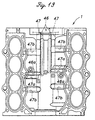
- the fresh air passage 47 formed in the bottom of the valley between the two cylinder banks B in the upper block 1 along the crankshaft axial line also communicates with each cam actuator chamber (not shown in the drawings) via a passage 47b extending along the cylinder axial line. Thereby, the oil in the cam actuator chamber is prevented from being degraded by contact with the blowby gas through ventilation of the interior of the cam actuator chamber.
- a relatively large blowby gas passage and a fresh air passage can be provided without increasing the size of the engine or complicating the structure thereof.
- the ventilation efficiency can be improved.
- by elimination of the need for a connecting member such as a rubber hose a significant contribution is made in reducing the number of component parts and the amount of assembly work.
- the passage length can be reduced, the efficiency of ventilation can be effectively improved.
- the intake manifold can be placed immediately adjacent to the upper block, and this contributes to the compact design of the engine.
- blowby gas passage and the fresh air passage were defined in the interface between the cylinder block lower case and the oil pan upper member, but it is also possible to form one or both of them between the interface between the cylinder block upper and lower cases.
- the necessary modification for such an embodiment is obvious for a person skilled in the art by referring to the foregoing description of the preferred embodiment.
- a blowby gas passage (25) and a fresh air passage (26) are defined between adjoining crankcase members so as to extend in parallel with a crankshaft axial line along either side of a lower part of said crankcase assembly.
- the crankcase is configured to receive the rotating crankshaft (7) provided with counterweights, it necessarily has a circular cross section. Therefore, this arrangement allows effective utilization of the available space.
- a cavity of a required volume for effective oil separation and pressure pulsation damping can be formed in the engine main body without increasing the number of components parts, and without complicating or increasing the size of the overall structure.
Abstract
Description
- The present invention relates to an engine crankcase ventilation system, and in particular to an engine crankcase ventilation system which allows a relatively large oil separation chamber or passage to be defined without increasing the size of the engine.
- Typically, a crankcase ventilation passage opens into the crankcase of an engine for recycling the blowby gas, which has passed through the gap between the pistons and cylinders, to the intake system, and to control the pressure pulsation due to the reciprocating motion of the pistons (see Japanese patent laid-open publication No. 61-135914).
- The crankcase is filled with lubrication oil mist, and a certain amount of the oil mist inevitably enters the ventilation passage. However, an excessive introduction of oil into the blowby gas is not desirable because it adversely affects the quality of the exhaust gas and contributes to an increase in oil consumption. To avoid such an inconvenience, it has been proposed, for instance, in Japanese patent laid open publication No. 61-135914 to provide an oil separation chamber between the two cylinder banks of a V-engine.
- However, to achieve an adequate capability to separate oil, the oil separation chamber is required to have a certain volume, and the provision of such an oil separation chamber in the engine results in an increase in the number of components parts, and the complication and size increase of the overall structure.
- The blowby gas removed from the crankcase must be replaced by fresh air from the atmosphere. The pressure pulsation in the crankcase can be transmitted from a fresh air passage for introducing fresh air into the crankcase. Also, it is possible for the blowby gas to flow backward under special circumstances. To address these problems, it is therefore desirable to provide a relatively large passage or chamber for fresh air for both effective noise muffling and oil separation. However, it prevents a compact design of the engine.
- The blowby gas is typically passed through a passage which is adapted to remove oil mist therefrom, and is then forwarded to the downstream of a throttle valve so that hydrocarbon that may be contained in the blowby gas may be recycled to the engine intake to improve fuel efficiency and reduce engine emissions. Therefore, a passage must be defined between the crankcase typically provided in a lower part of the engine and the intake system which is typically provided in an upper part of the engine, and the need for such a passage tends to complicate the structure of the engine. Typically, rubber hoses are used for conducting blowby gas from the crankcase to the intake system.
- In view of such problems of the prior art, a primary object of the present invention is to provide an engine crankcase ventilation system which allows a relatively large blowby gas passage to be defined without increasing the size of the engine or increasing the number of component parts.
- A second object of the present invention is to provide an engine crankcase ventilation system which is provided with a relatively large fresh air passage as well as a relatively large blowby gas passage without increasing the size of the engine.
- A third object of the present invention is to provide an engine crankcase ventilation system which is compact in size and effective in removing oil from the blowby gas.
- According to the present invention, such objects can be accomplished by providing an engine crankcase ventilation system for an internal combustion engine including a plurality of crankcase members jointly defining a crankcase assembly, comprising: a blowby gas passage and a fresh air passage which are defined between adjoining crankcase members independently from each other. Thus, removal of blowby gas and introduction of fresh air can be accomplished in an efficient manner.
- Preferably, the blowby gas passage extends in parallel with a crankshaft axial line along a first side of a lower part of the crankcase assembly; and the fresh air passage extends in parallel with a crankshaft axial line along a second side of a lower part of the crankcase assembly.
- Because the crankcase is configured to receive the rotating crankshaft provided with counterweights, it necessarily has a circular cross section. Therefore, by defining the blowby gas passage and the fresh air passage along either side of the lower part of the crankcase assembly, it is possible to effectively utilize the available space. Thus, a cavity of a required volume for effective oil separation and pressure pulsation damping can be formed in the engine main body without increasing the number of components parts, and without complicating or increasing the size of the overall structure.
- To effectively remove oil from the blowby gas passage, it is desirable to reduce the flow velocity of the blowby gas. To this end, it is advantageous to ensure a relatively large volume for the blowby gas passage. For the same reason, the blowby gas passage is preferably provided with a middle part which is enlarged as compared with an inlet end thereof so as to define an expansion chamber. Also, providing baffle plates in the blowby gas passage so as to define a tortuous passage contributes to effective removal of oil from the blowby gas.
- Similar arrangements for the fresh air passage are advantageous for muffling low frequency engine noise, and effective removal of oil in case of a backflow of blowby gas.
- To maximize the effective volume of the blowby gas passage, the blowby gas passage may be defined by a cylinder block lower case and an oil pan upper member, and communicates with a space above oil received in an oil pan via an opening provided in an axial end of the blowby gas passage. According to a particularly preferred embodiment of the present invention, the opening in the axial end of the blowby gas passage is provided in a recess in an axial end of the crankcase assembly, and an opening communicating with the space above the oil is provided also within the recess, a communication passage being defined between these two openings by a cover plate placed over the recess. This arrangement provides an inlet to the blowby gas passage at an axial end thereof without complicating the fabrication process therefor. Similar arrangement may be used for the fresh air passage.
- The exit end of the blowby gas passage may be provided at the opposite axial end thereof. In this case, the blowby gas passage communicates with a downstream of a throttle valve via an exit end of the blowby gas passage defined by an opening formed in a recess provided in the opposite axial end of the crankcase assembly, and a communication passage defined between the recess and a cover plate placed over the recess.
- When the internal combustion engine consists of a multiple-cylinder V-engine, and an intake system is placed between two cylinder banks of the V-engine, the communication passage may be arranged so as to communicate with the downstream of the throttle body via a first passage defined in an upper middle pan of the crankcase assembly in parallel with the crankshaft axial line, and a second passage defined along a side of the cylinder bank and extending perpendicularly from a middle part of the first passage along a cylinder axial line.
- To simplify the communication between the blowby gas passage and the intake system, passages may be defined in the cylinder head and the intake system in such a manner that the cylinder head passage and the intake system passage communicate with each other via opposing openings in mating surfaces of the cylinder head and the intake system.
- To form the second passage while allowing the intake system to be placed close to a side of a cylinder bank so as make optimum use of the available space, the second passage may defined in a ridge formed in a corresponding part of the cylinder bank while the intake system is provided with a recess for receiving the ridge.
- These arrangements for the blowby gas passage are equally applicable to the fresh air passage for similar advantages. It is desirable to ventilate the cam chamber in the cylinder head. To this end, the first passage for fresh air may communicate with a cam chamber defined above the cylinder head via a third passage defined along a side of the cylinder bank and extending perpendicularly from the first passage along a cylinder axial line.
- Now the present invention is described in the following with reference to the appended drawings, in which:
- Figure 1 is a front view of the crank pulley end of a V-engine embodying the present invention;
- Figure 2 is a bottom view of the lower block of the engine illustrated in Figure 1 which is adapted to be joined to an oil pan upper member;
- Figure 3 is a sectional view taken along line III-III of Figure 1;
- Figure 4 is a fragmentary front view of the crank pulley end of the V-engine shown in Figure 1;
- Figure 5 is a sectional view of an essential part taken along line V-V of Figure 4;
- Figure 6 is a fragmentary view of the transmission end of the V-engine shown in Figure 1;
- Figure 7 is a sectional view of an essential part taken along line VII-VII of Figure 6;
- Figure 8 is a sectional view of an essential part taken along line VIII-VIII of Figure 6;
- Figure 9 is a plan view of the engine shown in Figure 1 along with the associated intake system;
- Figure 10 is a fragmentary sectional view of an essential part taken along line X-X of Figure 9;
- Figure 11 is a fragmentary sectional view of an essential part taken along line XI-XI of Figure 9;
- Figure 12 is a fragmentary sectional view of an essential part taken along line XII-XII of Figure 10; and
- Figure 13 is a plan view of the cylinder block of the engine shown in Figure 1.
-
- Figure 1 is a front view showing a crank pulley end of a four-stroke, eight-cylinder V engine embodying the present invention. In Figure 1, the intake system which is described later in this description is omitted for the clarity of illustration.
- This engine E comprises an
upper block 1 having a V-shape so as to define a 90 angle between axial lines of cylinder banks B, alower block 2 attached to a lower surface of theupper block 1, anoil pan 3 attached to a lower surface of thelower block 2, and acylinder head 4 attached to the upper surface of each cylinder bank B of theupper block 1. In this embodiment, theoil pan 3 comprises anupper member 3a made of a die cast aluminum alloy, and alower member 3b made of stamped steel plate, and these two parts are attached to each other by a number of threaded bolts. A pair ofcamshafts 5 are disposed above each of thecylinder heads 4. Thesecamshafts 5 are covered by ahead cover 6 attached to the upper surface of thecorresponding cylinder head 4. A crankshaft 7 is supported in the interface between theupper block 1 and thelower block 2 via a main bearing. - A
compressor 8 for an air conditioner is attached to a part of theupper block 1 on one side of the crankshaft 7 (to the right in Figure 1), and an AC generator 9 is attached to a part of thelower block 2 on the other side of the crankshaft 7 (to the left in Figure 1). Thecompressor 8 and the AC generator 9 are driveably connected to the crankshaft 7 via a belt and pulley mechanism not shown in the drawing. - A
crank sprocket 10 is fitted on a part of the crankshaft 7 somewhat inward from the crank pulley, and a drive pinion 11 is fitted on a part of the crankshaft 7 which is even more inward. - The drive pinion 11 meshes with a pair of driven
pinions 12 which are disposed at symmetric positions with respect to a plane which bisects the angle between the two cylinder banks B and passes through the axial center of the crankshaft 7. Each of these drivenpinions 12 is integrally provided with asmall sprocket 13, and asilent chain 15 is passed around each of thesmall sprockets 13 andcam sprockets 14 fitted on the associated pair ofcamshafts 5 to actuate the cams. Thus, the rotational power of the crankshaft 7 is transmitted to the twocamshafts 5 provided on each of thecylinder heads 4. - The
upper block 1 and thelower block 2 are separated from each other by a horizontal plane through which the axial center of the crankshaft 7 passes, and a pair ofbalancer shafts - One of the
balancer shafts 16b which is supported on the side of thelower block 2 is fitted with abalancer shaft sprocket 17 at an axial end thereof. Asilent chain 19 is passed around thisbalancer shaft sprocket 17, thecrank sprocket 10, and a pump sprocket 18 attached to an oil pump (not shown in the drawing) which is in turn mounted to the lower surface of thelower block 2 so that thelower balancer shaft 16b and the oil pump may be actuated by the crankshaft 7. - The two
balancer shafts gears corresponding balancer shafts sprocket 17. This arrangement is adapted to cancel the horizontal component of the unbalance inertia force due to the motion of the pistons in the V-shaped cylinder banks. - The
silent chains 15 passed around thecam sprockets 14 of thecorresponding camshafts 5, as well as thesilent chain 19 passed around thebalancer shafts sprockets 17 and the pump sprocket 18, are each provided with achain tensioner 22 for automatically adjusting pressure application on the chain by using ahydraulic plunger 21, and achain guide 23 for restricting lateral motion of the chain. Thechain tensioner 22 and thechain guide 23 are attached to the crank pulley side end surface of theupper block 1,lower block 2,oil pan 3 andcylinder heads 4 by using threaded bolts. The crank pulley end of the engine E is substantially entirely covered by a chain cover (not shown in the drawing). - Referring to Figures 2 and 3, a
blowby gas chamber 25 for removing oil from the blowby gas which is recycled from thecrankcase 24 to the intake system is provided on the right side of the interface between thelower block 2 and theoil pan 3 as seen in Figure 1. Afresh air chamber 26 for admitting fresh air from the intake system into thecrankcase 24 is provided on the left side of this interface. - The two
chambers lower block 2. Thechamber ribs 27 projecting perpendicularly with respect to the flow line or the axial line of the crankshaft 7 from either side wall in an alternating fashion. Theseribs 27 not only enhance the oil separating capability by defining a tortuous passage but also are effective in avoiding the reduction in the rigidity due to the creation of such large cavities. - The upper walls of the two
chambers baffle walls 29 which correspond to the rotational trajectory of thecounterweights 28 formed integrally with the crankshaft 7, and separate thecrankcase 24 defined in the upper andlower blocks oil pan 3. Theblowby gas chamber 25 partly overlaps with abalancer shaft chamber 30, defined on the left side of thecrankcase 24, as seen from a side. In other words, theblowby gas chamber 25 is defined between thebaffle 29 and thebalancer shaft 30 as seen from the axial end of the crankshaft 7. Thereby, an available space is not wasted, and an oil separation chamber having a relatively large volume can be formed without increasing the overall size of the engine. - The
fresh air chamber 26 is normally free from any oil because it constantly receives a supply of fresh air, but is provided with a tortuous passage in view of a possibility of the blowby gas flowing backward. - The part of the inner surface of the left side wall of the
lower block 2, as seen in Figure 3, on which thebaffle 29 is placed, is provided with aslanted passage 31 which slants downward toward the bottom of thebalancer shaft chamber 30. Thebalancer shaft chamber 30 opens out to theleft oil passage 32 formed in the interface between thelower block 2 and theoil pan 3 via avertical passage 33 appropriately formed in the bottom wall of thebalancer shaft chamber 30. - A
cast hole 35 is provided in the part of thebaffle 29 adjoining the right inner side wall of thelower block 2 as seen in Figure 3, and thiscast hole 35 communicates with aright oil passage 34 which is formed in the interface between thelower block 2 and theoil pan 3. The lower part of the crankcase is defined by aplate member 36 made of stamped steel plate extending along the trajectory of thecounterweight 28. The oil in the crankcase which is thrown up by thecounter weights 28 of the crankshaft 7 can thus return to theoil pan 3 in a short time via thepassages 31 to 35. The plate member prevents the motion of the crankshaft 7 or the wind pressure caused by this motion from disturbing the surface of the lubiricating oil received in theoil pan 3. - Referring to Figures 4 and 5, the opening of the
blowby gas chamber 25 on the end surface of thelower block 2 on the side of the crank pulley consists of a plurality ofsmall holes 37 which communicate with the space above the oil surface in theoil pan 3 via ahole 38 formed in the end wall of theoil pan 3. This area, which is provided with thesmall holes 37 and thehole 38, is surrounded by arib 39, and is closed, at its front end, by asupport base 23a of thechain guide 23 with the support base being attached to the free end of therib 39 between thebalancer shaft sprocket 17 and the pump sprocket 18. - The blowby gas containing oil mist thus flows into the
blowby gas chamber 25 from the gap G between the inner surface of thesupport base 23a of thechain guide 23 and the front surface of thelower block 2 via the small holes 37 (see the arrow in Figure 5). The oil mist is separated also as the blowby gas passes though this gap G and the small holes 37. - The
chain guide 23 is attached to thelower block 2 and theoil pan 3 at its lower and upper ends by a first fastening portion F1 and a second fastening portion F2, respectively, and thesupport base 23a is additionally attached by a third fastening portion F3. - The part of the end wall on the side of the crank pulley surrounding the
fresh air chamber 26 is likewise provided with arib 40. In this case, therib 40 cooperates with the rib provided on the inner surface of a chain cover not shown in the drawing so as to define a passage between ahole 41 in the end wall of thelower block 2 and ahole 42 in the end wall of theoil pan 3. Therib 40 is provided with anotch 43 to permit fresh air to be introduced into the interior of the chain cover. - On the end wall of the upper and
lower blocks hole 44 on the other end of theblowby gas chamber 25 and ahole 45 on the other end of thefresh air chamber 26 as shown in Figure 6. The end wall is additionally provided withrecesses blowby gas passages 46 and a pair offresh air passages 47 provided in theupper block 1 at the bottom of the valley between the two cylinder banks B with theholes chambers end plate 50 over the vertical surface V surrounding theserecesses communication passages blowby gas chamber 25 and thefresh air chamber 26, respectively (see Figures 7 and 8). Thesepassages blowby gas chamber 25 and thefresh air chamber 26 so as to achieve a capability to separate oil from the blowby gas although it is not shown in the drawings. - Between the two cylinder banks B is provided an
intake manifold assembly 53 at a symmetric position bisecting the cylinder axial lines as best shown in Figures 9 to 11. Theintake manifold assembly 53 comprises a pair ofthrottle bodies 54 which are located at intermediate points along the crankshaft axial line with the axial line of their inlet ports extending perpendicularly to the axial line of the crankshaft 7, a pair ofsurge tanks 55 which are elongated along the crankshaft axial line and associated with therespective throttle bodies 54, anintake chamber 56 extending in the crankshaft axial line between the two cylinder banks of theupper block 1, and eightintake pipes 58 extend from the upper surface of theintake chamber 56 to theintake ports 57 of the corresponding cylinders in a spiral manner. Theintake manifold 53 is itself attached to a horizontal plane H defined in thecylinder heads 4 between the two cylinder banks. In the case of the engine of this embodiment, it is possible to select one of two possible modes depending on the load condition of the engine so that the intake to theintake ports 57 of the respective cylinders may be passed either directly through thesurge tank 55 or via theintake chambers 56 and thespiral intake pipes 58. - Each of the
cylinder heads 4 is provided withpassages parts blowby gas passage 46 andfresh air passage 47 extending along the cylinder axial line, theblowby gas passage 46 andfresh air passage 47 being defined inside theupper block 1. Theintake manifold assembly 53 is provided withpassages passages upper block 1. Thus, fresh air is drawn from the upstream 54a of the throttle valve of thethrottle body 54, and blowby gas is forwarded to the downstream 54b of the throttle valve of the throttle body. In other words, the blowby gas passages and the fresh air passages are partly defined in thecylinder head 4, theupper block 1 and theintake manifold 53, and theparts cylinder head 4 directly communicate with the correspondingparts intake manifold 53 at the interface (the horizontal plate H) between thecylinder head 4 and theintake manifold 53. - The
PCV valve 63 is firmly held in the interface between thecylinder head 4 and the intake manifold assembly 53 (the opening of theblowby gas passage 59 of thecylinder head 4 facing the intake manifold 53), and would not inadvertently dislodge therefrom. - As discussed above, the
throttle bodies 54 are located in a middle part along the crankshaft axial line of theintake manifold 53, and theblowby gas passage 61 communicating with the downstream 54b of the throttle valve, as well as the fresh air passage communicating with the upstream 54a of the throttle valve, is located in a middle part along the crankshaft axial line of thecylinder head 4. As a result, the length of the passage communicating the intake manifold 53 (intake system) with thepassages upper block 1 along the crankshaft axial line can be minimized, and this contributes to the improvement of the efficiency of ventilation. - The surface of the
upper block 1 facing theintake manifold 53 is formed with aridge 64 on each cylinder bank which is internally provided with ablowby gas passage 46a and afresh air passage 47a. Theintake manifold 53 is provided with arecess 65 corresponding to theridge 64 between a pair of adjacent intake pipes 58 (see Figure 12). As a result, theintake manifold 53 can be placed immediately adjacent to theupper block 1, and this contributes to the compact design of the engine. - The blowby gas from the
blowby gas chamber 25 is divided between the intake systems of the two cylinder banks B, and ultimately flows into the commonfresh air chamber 26 via the respective intake systems of the two cylinder banks B. As shown in Figure 13, thefresh air passage 47 formed in the bottom of the valley between the two cylinder banks B in theupper block 1 along the crankshaft axial line also communicates with each cam actuator chamber (not shown in the drawings) via apassage 47b extending along the cylinder axial line. Thereby, the oil in the cam actuator chamber is prevented from being degraded by contact with the blowby gas through ventilation of the interior of the cam actuator chamber. - As discussed above, according to a certain aspect of the present invention, a relatively large blowby gas passage and a fresh air passage can be provided without increasing the size of the engine or complicating the structure thereof. In particular, by providing these passages independently from each other, the ventilation efficiency can be improved. According to another aspect of the present invention, by elimination of the need for a connecting member such as a rubber hose, a significant contribution is made in reducing the number of component parts and the amount of assembly work. Also, because the passage length can be reduced, the efficiency of ventilation can be effectively improved. According to another aspect of the present invention, the intake manifold can be placed immediately adjacent to the upper block, and this contributes to the compact design of the engine.
- Although the present invention has been described in terms of a preferred embodiment thereof, it is obvious to a person skilled in the art that various alterations and modifications are possible without departing from the scope of the present invention which is set forth in the appended claims. For instance, the blowby gas passage and the fresh air passage were defined in the interface between the cylinder block lower case and the oil pan upper member, but it is also possible to form one or both of them between the interface between the cylinder block upper and lower cases. The necessary modification for such an embodiment is obvious for a person skilled in the art by referring to the foregoing description of the preferred embodiment.
- In an engine crankcase ventilation system, a blowby gas passage (25) and a fresh air passage (26) are defined between adjoining crankcase members so as to extend in parallel with a crankshaft axial line along either side of a lower part of said crankcase assembly. Because the crankcase is configured to receive the rotating crankshaft (7) provided with counterweights, it necessarily has a circular cross section. Therefore, this arrangement allows effective utilization of the available space. Thus, a cavity of a required volume for effective oil separation and pressure pulsation damping can be formed in the engine main body without increasing the number of components parts, and without complicating or increasing the size of the overall structure.
Claims (17)
- An engine crankcase ventilation system for an internal combustion engine including a plurality of crankcase members jointly defining a crankcase assembly, comprising:a blowby gas passage (25) and a fresh air passage (26) which are defined between adjoining crankcase members (3a, 4) independently from each other.
- An engine crankcase ventilation system according to claim 1, wherein said blowby gas passage (25) extends in parallel with a crankshaft axial line along a first side of a lower part of said crankcase assembly; and said fresh air passage (26) extends in parallel with a crankshaft axial line along a second side of a lower part of said crankcase assembly.
- An engine crankcase ventilation system according to claim 1, wherein said blowby gas passage is provided with a middle part which is enlarged as compared with an inlet end thereof so as to define an expansion chamber.
- An engine crankcase ventilation system according to claim 3, wherein said blowby gas passage is provided with baffle plates (27) so as to define a tortuous passage.
- An engine crankcase ventilation system according to claim 2, wherein said blowby gas passage is defined by a cylinder block lower case (4) and an oil pan upper member (3a), and communicates with a space above oil received in an oil pan (3b) via an opening (37) provided in an axial end of said blowby gas passage.
- An engine crankcase ventilation system according to claim 5, wherein said opening (37) in the axial end of said blowby gas passage is provided in a recess (39) in an axial end of said crankcase assembly, and an opening (38) communicating with said space above the oil is provided also within said recess, a communication passage being defined between these two openings by a cover plate (23a) placed over said recess.
- An engine crankcase ventilation system according to claim 5, wherein said blowby gas passage communicates with downstream (54b) of a throttle valve via an exit end (44) of said blowby gas passage defined by an opening formed in a recess (48) provided in the opposite axial end of said crankcase assembly, and a communication passage defined between said recess and a cover plate placed over said recess.
- An engine crankcase ventilation system according to claim 7, wherein said internal combustion engine consists of a multiple-cylinder V-engine, and an intake system (53) is placed between two cylinder banks of said V-engine, said communication passage communicating with the downstream of said throttle body via a first passage (46) defined in an upper middle part of the crankcase assembly in parallel with the crankshaft axial line, and a second passage (46a) defined along a side of the cylinder bank and extending perpendicularly from a middle part of said first passage along a cylinder axial line.
- An engine crankcase ventilation system according to claim 8, wherein said second passage communicates with the downstream of said throttle body via a passage (59) defined in a cylinder head, and a passage (61) defined in said intake system, and said cylinder head passage and said intake system passage communicate with each other via opposing openings in mating surfaces (H) of said cylinder head and said intake system.
- An engine crankcase ventilation system according to claim 8, wherein said second passage is defined in a ridge (64) formed in a corresponding part of said cylinder bank, and said intake system is provided with a recess (65) for receiving said ridge.
- An engine crankcase ventilation system according to claim 2, wherein said fresh air passage (26) is defined by a cylinder block lower case and an oil pan upper member, and communicates with a space above oil received in an oil pan via an opening (41) provided in an axial end of said fresh air gas passage.
- An engine crankcase ventilation system according to claim 11, said opening in the axial end of said fresh air passage is provided in a recess (40) in an axial end of said crankcase assembly, and an opening (42) communicating with said space above the oil is provided also within said recess, a communication passage being defined between these two openings by a cover plate placed over said recess.
- An engine crankcase ventilation system according to claim 12, wherein said fresh air passage communicates with upstream (54a) of a throttle valve via an inlet end of said fresh air passage defined by an opening (45) formed in a recess (49) provided in the opposite axial end of said crankcase assembly, and a communication passage defined between said recess and a cover plate placed over said recess.
- An engine crankcase ventilation system according to claim 13, wherein said internal combustion engine consists of a multiple-cylinder V-engine, and an intake system is placed between two cylinder banks of said V-engine, said communication passage communicating with the upstream of said throttle body via a first passage (47) defined in an upper middle part of the crankcase assembly in parallel with the crankshaft axial line, and a second passage (47a) defined along a side of the cylinder bank and extending perpendicularly from a middle part of said first passage along a cylinder axial line.
- An engine crankcase ventilation system according to claim 14, wherein said second passage communicates with the upstream of said throttle body via a passage (60) defined in a cylinder head, and a passage (62) defined in said intake system, and said cylinder head passage and said intake system passage communicate with each other via opposing openings in mating surfaces (H) of said cylinder head and said intake system.
- An engine crankcase ventilation system according to claim 15, wherein said second passage is defined in a ridge (64) formed in a corresponding part of said cylinder bank, and said intake system is provided with a recess (65) for receiving said ridge.
- An engine crankcase ventilation system according to claim 15, wherein said first passage for fresh air communicates with a cam chamber defined above said cylinder head via a third passage (47b) defined along a side of the cylinder bank and extending perpendicularly from said first passage along a cylinder axial line.
Applications Claiming Priority (4)
| Application Number | Priority Date | Filing Date | Title |
|---|---|---|---|
| JP11024106A JP2000220434A (en) | 1999-02-01 | 1999-02-01 | Crankcase bleeding passage |
| JP2410699 | 1999-02-01 | ||
| JP03041799A JP4260264B2 (en) | 1999-02-08 | 1999-02-08 | Crankcase ventilation passage |
| JP3041799 | 1999-02-08 |
Publications (2)
| Publication Number | Publication Date |
|---|---|
| EP1026372A1 true EP1026372A1 (en) | 2000-08-09 |
| EP1026372B1 EP1026372B1 (en) | 2004-09-22 |
Family
ID=26361595
Family Applications (1)
| Application Number | Title | Priority Date | Filing Date |
|---|---|---|---|
| EP00101516A Expired - Lifetime EP1026372B1 (en) | 1999-02-01 | 2000-01-26 | Engine crankcase ventilation system including a blowby gas passage defined between crankcase members |
Country Status (5)
| Country | Link |
|---|---|
| US (1) | US6279554B1 (en) |
| EP (1) | EP1026372B1 (en) |
| KR (1) | KR100339509B1 (en) |
| CA (1) | CA2297307C (en) |
| DE (1) | DE60013923T2 (en) |
Cited By (4)
| Publication number | Priority date | Publication date | Assignee | Title |
|---|---|---|---|---|
| DE10105555A1 (en) * | 2001-02-06 | 2002-08-08 | Volkswagen Ag | Device for ventilating oil-charged gases in an internal combustion engine, has vent connection carrying the gases and forming a section on a cylinder head of the engine fitted with an intake unit feeding in combustion air |
| CN101981291B (en) * | 2008-03-31 | 2013-02-06 | 本田技研工业株式会社 | Internal combustion engine for small-sized vehicle |
| CN109899173A (en) * | 2019-04-10 | 2019-06-18 | 广西玉柴机器股份有限公司 | Improve the cylinder in V-arrangement body structure of body rigidity and NVH performance |
| CN109899172A (en) * | 2019-04-10 | 2019-06-18 | 广西玉柴机器股份有限公司 | A kind of twin-six cylinder block |
Families Citing this family (9)
| Publication number | Priority date | Publication date | Assignee | Title |
|---|---|---|---|---|
| KR100401914B1 (en) * | 2001-06-25 | 2003-10-17 | 현대자동차주식회사 | Oil separator for blow by gas |
| JP4032878B2 (en) * | 2002-08-23 | 2008-01-16 | 三菱ふそうトラック・バス株式会社 | Breather device for internal combustion engine |
| KR20040020315A (en) * | 2002-08-30 | 2004-03-09 | 현대자동차주식회사 | Structure of cylinder block for engine |
| JP4573743B2 (en) * | 2005-09-30 | 2010-11-04 | 本田技研工業株式会社 | Power unit with transmission mechanism for driving auxiliary equipment |
| JP4225327B2 (en) * | 2006-07-11 | 2009-02-18 | トヨタ自動車株式会社 | Oil return structure for internal combustion engine |
| DE102007006938A1 (en) * | 2007-02-13 | 2008-08-14 | Robert Bosch Gmbh | Method and device for diagnosing a crankcase ventilation of an internal combustion engine |
| JP2008223880A (en) * | 2007-03-13 | 2008-09-25 | Yamaha Motor Co Ltd | Internal combustion engine and vehicle equipped with the same |
| DE102016219344A1 (en) * | 2016-10-06 | 2018-04-12 | Bayerische Motoren Werke Aktiengesellschaft | Device for venting a crankcase of an internal combustion engine |
| CN109386345A (en) * | 2018-11-09 | 2019-02-26 | 廊坊舒畅汽车零部件有限公司 | Joint assembly, crankcase ventilation system and automobile |
Citations (6)
| Publication number | Priority date | Publication date | Assignee | Title |
|---|---|---|---|---|
| JPS56135914A (en) | 1980-03-27 | 1981-10-23 | Toshiba Corp | Oil-immersed dc induction electric apparatus |
| EP0291358A2 (en) * | 1987-05-15 | 1988-11-17 | Honda Giken Kogyo Kabushiki Kaisha | Internal combustion engine |
| JPH03182614A (en) * | 1989-12-11 | 1991-08-08 | Mazda Motor Corp | Crankcase structure for multiple cylinder engine |
| GB2260365A (en) * | 1991-10-03 | 1993-04-14 | Jaguar Cars | Oil Separation from i.c. engine crankcase gases |
| EP0705964A2 (en) * | 1994-10-07 | 1996-04-10 | Yamaha Hatsudoki Kabushiki Kaisha | Internal combustion engine |
| DE19720383A1 (en) * | 1997-05-15 | 1998-11-19 | Daimler Benz Ag | Breather device for crankcase of multi=cylinder internal combustion engine |
Family Cites Families (7)
| Publication number | Priority date | Publication date | Assignee | Title |
|---|---|---|---|---|
| US4515137A (en) * | 1984-02-08 | 1985-05-07 | John Manolis | Crankcase emissions device |
| JPS61135914A (en) | 1984-12-04 | 1986-06-23 | Honda Motor Co Ltd | Breezer device for engine |
| CA1274133C (en) * | 1984-12-04 | 1990-09-18 | Crank case ventilation system | |
| JP2678294B2 (en) * | 1988-09-13 | 1997-11-17 | マツダ株式会社 | Blow-by gas recirculation system for V-type engine |
| US5069192A (en) * | 1989-10-24 | 1991-12-03 | Nissan Motor Company, Ltd. | Internal combustion engine with crankcase ventilation system |
| US5261380A (en) | 1992-07-15 | 1993-11-16 | Ford Motor Company | Crankcase ventilation system for automotive engine |
| JP3389801B2 (en) * | 1996-11-29 | 2003-03-24 | スズキ株式会社 | Engine blow-by gas reduction structure |
-
2000
- 2000-01-26 EP EP00101516A patent/EP1026372B1/en not_active Expired - Lifetime
- 2000-01-26 DE DE60013923T patent/DE60013923T2/en not_active Expired - Fee Related
- 2000-01-27 CA CA002297307A patent/CA2297307C/en not_active Expired - Fee Related
- 2000-01-28 US US09/494,141 patent/US6279554B1/en not_active Expired - Fee Related
- 2000-01-31 KR KR1020000004740A patent/KR100339509B1/en not_active IP Right Cessation
Patent Citations (6)
| Publication number | Priority date | Publication date | Assignee | Title |
|---|---|---|---|---|
| JPS56135914A (en) | 1980-03-27 | 1981-10-23 | Toshiba Corp | Oil-immersed dc induction electric apparatus |
| EP0291358A2 (en) * | 1987-05-15 | 1988-11-17 | Honda Giken Kogyo Kabushiki Kaisha | Internal combustion engine |
| JPH03182614A (en) * | 1989-12-11 | 1991-08-08 | Mazda Motor Corp | Crankcase structure for multiple cylinder engine |
| GB2260365A (en) * | 1991-10-03 | 1993-04-14 | Jaguar Cars | Oil Separation from i.c. engine crankcase gases |
| EP0705964A2 (en) * | 1994-10-07 | 1996-04-10 | Yamaha Hatsudoki Kabushiki Kaisha | Internal combustion engine |
| DE19720383A1 (en) * | 1997-05-15 | 1998-11-19 | Daimler Benz Ag | Breather device for crankcase of multi=cylinder internal combustion engine |
Non-Patent Citations (1)
| Title |
|---|
| PATENT ABSTRACTS OF JAPAN vol. 015, no. 432 (M - 1175) 5 November 1991 (1991-11-05) * |
Cited By (6)
| Publication number | Priority date | Publication date | Assignee | Title |
|---|---|---|---|---|
| DE10105555A1 (en) * | 2001-02-06 | 2002-08-08 | Volkswagen Ag | Device for ventilating oil-charged gases in an internal combustion engine, has vent connection carrying the gases and forming a section on a cylinder head of the engine fitted with an intake unit feeding in combustion air |
| DE10105555B4 (en) * | 2001-02-06 | 2016-02-25 | Volkswagen Ag | Ventilation device for oil-laden gases of an internal combustion engine |
| CN101981291B (en) * | 2008-03-31 | 2013-02-06 | 本田技研工业株式会社 | Internal combustion engine for small-sized vehicle |
| CN109899173A (en) * | 2019-04-10 | 2019-06-18 | 广西玉柴机器股份有限公司 | Improve the cylinder in V-arrangement body structure of body rigidity and NVH performance |
| CN109899172A (en) * | 2019-04-10 | 2019-06-18 | 广西玉柴机器股份有限公司 | A kind of twin-six cylinder block |
| CN109899173B (en) * | 2019-04-10 | 2022-06-07 | 广西玉柴机器股份有限公司 | V-shaped cylinder block structure capable of improving rigidity and NVH (noise, vibration and harshness) performance of engine body |
Also Published As
| Publication number | Publication date |
|---|---|
| DE60013923D1 (en) | 2004-10-28 |
| US6279554B1 (en) | 2001-08-28 |
| EP1026372B1 (en) | 2004-09-22 |
| KR100339509B1 (en) | 2002-06-01 |
| KR20000057847A (en) | 2000-09-25 |
| CA2297307C (en) | 2006-03-07 |
| CA2297307A1 (en) | 2000-08-01 |
| DE60013923T2 (en) | 2005-01-27 |
Similar Documents
| Publication | Publication Date | Title |
|---|---|---|
| CA1328588C (en) | Internal combustion engine | |
| US7637236B2 (en) | Cylinder head for an overhead-cam internal combustion engine, engine incorporating same, and vehicle incorporating the engine | |
| EP1026372B1 (en) | Engine crankcase ventilation system including a blowby gas passage defined between crankcase members | |
| EP0837236A1 (en) | Oil pan and bearings structure for crankshaft | |
| CN107524538B (en) | Internal combustion engine | |
| JP2006183516A (en) | Oil strainer support structure in engine | |
| EP1676982B1 (en) | Cam drive gear and valve operating system drive gear for engine | |
| US5873336A (en) | Cam drive system for engine | |
| JP2802440B2 (en) | Engine unit for vehicle | |
| JP2001303924A (en) | Blowby gas separator device | |
| JP3942698B2 (en) | Blow-by gas reduction device for DOHC engine for outboard motor | |
| JP2002266614A (en) | Overhead camshaft type v-engine | |
| JP2888383B2 (en) | Breather chamber arrangement structure of internal combustion engine | |
| JP5943978B2 (en) | Breather equipment | |
| JP4260264B2 (en) | Crankcase ventilation passage | |
| US20060037311A1 (en) | Secondary air supply for engine exhaust system | |
| JPH07174010A (en) | V type vertical engine | |
| JP4255552B2 (en) | V-type engine crankcase ventilation passage | |
| US8528515B2 (en) | Crankcase of internal combustion engine | |
| JP4335342B2 (en) | Crankcase ventilation passage | |
| JPH0763034A (en) | Oil passage of drysump engine | |
| JP3892948B2 (en) | Lubricating device for DOHC type engine for outboard motor | |
| JP2000220434A (en) | Crankcase bleeding passage | |
| JP2003184533A (en) | Oil-separator structure for engine | |
| JPH1162537A (en) | Lubricating device for outboard engine |
Legal Events
| Date | Code | Title | Description |
|---|---|---|---|
| PUAI | Public reference made under article 153(3) epc to a published international application that has entered the european phase |
Free format text: ORIGINAL CODE: 0009012 |
|
| AK | Designated contracting states |
Kind code of ref document: A1 Designated state(s): DE GB |
|
| AX | Request for extension of the european patent |
Free format text: AL;LT;LV;MK;RO;SI |
|
| 17P | Request for examination filed |
Effective date: 20000619 |
|
| AKX | Designation fees paid |
Free format text: DE GB |
|
| 17Q | First examination report despatched |
Effective date: 20030721 |
|
| GRAP | Despatch of communication of intention to grant a patent |
Free format text: ORIGINAL CODE: EPIDOSNIGR1 |
|
| GRAS | Grant fee paid |
Free format text: ORIGINAL CODE: EPIDOSNIGR3 |
|
| GRAA | (expected) grant |
Free format text: ORIGINAL CODE: 0009210 |
|
| AK | Designated contracting states |
Kind code of ref document: B1 Designated state(s): DE GB |
|
| REG | Reference to a national code |
Ref country code: GB Ref legal event code: FG4D |
|
| REF | Corresponds to: |
Ref document number: 60013923 Country of ref document: DE Date of ref document: 20041028 Kind code of ref document: P |
|
| PLBE | No opposition filed within time limit |
Free format text: ORIGINAL CODE: 0009261 |
|
| STAA | Information on the status of an ep patent application or granted ep patent |
Free format text: STATUS: NO OPPOSITION FILED WITHIN TIME LIMIT |
|
| 26N | No opposition filed |
Effective date: 20050623 |
|
| PGFP | Annual fee paid to national office [announced via postgrant information from national office to epo] |
Ref country code: GB Payment date: 20070124 Year of fee payment: 8 |
|
| GBPC | Gb: european patent ceased through non-payment of renewal fee |
Effective date: 20080126 |
|
| PG25 | Lapsed in a contracting state [announced via postgrant information from national office to epo] |
Ref country code: GB Free format text: LAPSE BECAUSE OF NON-PAYMENT OF DUE FEES Effective date: 20080126 |
|
| PGFP | Annual fee paid to national office [announced via postgrant information from national office to epo] |
Ref country code: DE Payment date: 20090123 Year of fee payment: 10 |
|
| PG25 | Lapsed in a contracting state [announced via postgrant information from national office to epo] |
Ref country code: DE Free format text: LAPSE BECAUSE OF NON-PAYMENT OF DUE FEES Effective date: 20100803 |