EP1025890A2 - Verfahren und Vorrichtung zur Umsetzung von elektrischen Signalen in bewegte Bilder - Google Patents
Verfahren und Vorrichtung zur Umsetzung von elektrischen Signalen in bewegte Bilder Download PDFInfo
- Publication number
- EP1025890A2 EP1025890A2 EP00101334A EP00101334A EP1025890A2 EP 1025890 A2 EP1025890 A2 EP 1025890A2 EP 00101334 A EP00101334 A EP 00101334A EP 00101334 A EP00101334 A EP 00101334A EP 1025890 A2 EP1025890 A2 EP 1025890A2
- Authority
- EP
- European Patent Office
- Prior art keywords
- lens
- image
- kaleidoscope
- oscilloscope
- camera
- Prior art date
- Legal status (The legal status is an assumption and is not a legal conclusion. Google has not performed a legal analysis and makes no representation as to the accuracy of the status listed.)
- Withdrawn
Links
Images


Classifications
-
- A—HUMAN NECESSITIES
- A63—SPORTS; GAMES; AMUSEMENTS
- A63J—DEVICES FOR THEATRES, CIRCUSES, OR THE LIKE; CONJURING APPLIANCES OR THE LIKE
- A63J17/00—Apparatus for performing colour-music
Definitions
- the invention relates to a method and a device for converting modulated and acoustically reproducible electrical signals into moving images.
- discotheques or at outdoor events it is common to play music from sound carriers or to produce live music on a stage and, in addition, to run moving pictures on large screens or projection screens.
- the visual performances can be natural spectacles, sporting events or feature film scenes. As a rule, they have nothing to do with the music being played, but are supposed to entertain and stimulate the visitors on a second level.
- a sound signal is input into a microphone Frequency band filter fed. Its output channels become a multi-channel Input module supplied that a multiplexer and an analog-digital converter includes. The signal is passed to a microcomputer to be there calculate image-characterizing shape and color data. These become one Video signal generator supplied, which has the task of consisting of colored images Create surfaces and lines and change them quickly.
- the system uses a complex electronic system to generate the image patterns Circuit that first filters and digitizes audio signals and then using a Converts combination of software and hardware into visual signals.
- a light bulb serves as the light source, the light of which is passed through a rotatable color filter and a rotatable optical converter made of glass fibers.
- the image patterns generated in this way are alienated with the help of a prism and thrown onto a canvas using the imaging optics. Because of the necessary high light output and undesirable heat emission, thermal insulation and a cooling device are required.
- a synchronization with electrical signals (e.g. music) is not provided.
- the invention has for its object to provide a form of performance, the music. Singing or other acoustic signals are converted into sound images synchronously in order to achieve this To deepen the sound experience through visual impressions.
- the signal source is an oscilloscope or feeds a monitor that its image consisting of wave trains over alienating optical aids is recorded by a video camera and that this camera is a large screen projector, a monitor, a television or one Laser imager feeds.
- a collecting lens can be used as an alienating optical aid, which lens must be arranged at a certain distance between the screen and the camera.
- Even more striking effects can be achieved by several mirrors arranged at an acute angle to each other, which practically represent a kaleidoscope without its own picture elements.
- the mirrors represent a truncated pyramid.
- Fig. 1 denotes a signal source with two channels, which feed an oscilloscope 2 as an image generator.
- the curves of the screen image are recorded by a video camera 3.
- a lens 4 is arranged in the beam path between the oscilloscope and the camera and specifically alienates the oscilloscope image.
- the camera signals are fed via an image line 5 to an image display device 6 - here a video projector.
- Television sets, computer monitors or laser sky recorders can also be used for image reproduction.
- a CD player or any multi-channel player can be used as the signal source serve.
- Microphone amplifiers can also be used to transmit live music be used.
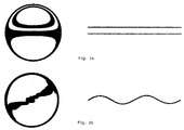
- FIG. 2a shows on the right two parallel straight lines on the oscilloscope screen and on the left the associated image, alienated by the lens 4, which the camera 3 records and which is thrown onto a screen with the image display device 6.
- the image in Fig. 2a shows an outer circle in which there are two ellipsoid. move deformed rings.
- a sine curve is given in Fig. 2b, it arises in Fig. 2b left an irregular, different wide band that penetrates the enveloping circle diagonally.
- the pictures are only static examples and cannot hint at the effect of the figures moving in the rhythm of the sound.
- the signal source 1 is in turn followed by an oscilloscope 2.
- a conical kaleidoscope 7 is arranged between it and the camera 3. His mirrors, which are conically arranged at a certain angle, reflect the curves that appear on the screen in such a way that imaginative polygonal figures emerge in the basic pattern, which change simultaneously with pitch and amplitude.
- Figures 4a and b show such figures.
- 4a shows on the left two parallel, straight lines on the oscilloscope, that is to say baselines with the amplitude Zero".
- the generated image in Fig. 4a right consists of regularly arranged double hexagons, the size of which increases from the inside out. In the center there are shadowy triangles. If, according to Fig. 4b, the signal transmitter emits a sound mixture on one channel and a sine line on the other channel, I will see a complicated pattern of rotationally symmetrical figures on the screen, which here resemble six-jet flowers.
- the base is an equilateral triangle with sides a, b, c.
- the body as a whole is a three-sided truncated pyramid.
- the smaller triangular opening is assigned to the image generator, i.e. the oscilloscope, the larger of the video camera.
- kaleidoscope 9 consisting of five mirrors, which is also designed as a truncated pyramid. All five tapered mirrors form the same angle. An internally mirrored hollow truncated cone would also be possible as an alienating optical aid.
- FIG. 7 shows how the oscilloscope 2 and the video camera 3 can be assigned to one another when a lens 4 is used to alienate the signals.
- the parts 2 and 3 are connected to one another by guide tubes 10 and 11, the position of the lens 4, as is customary in optical devices, being adaptable by tube adjustment or fine adjustment.
- Fig. 8 is a corresponding arrangement with kaleidoscope 7. In this form there is a large overall length. In order to develop a compact, handy device, it is advantageous to use deflecting mirrors or deflecting prisms.
- FIG. 9 shows such a solution with a kaleidoscope 7, which is placed in front of the video camera 3.
- Two mirrors 12, 13 deflect the light beams through 90 ° each.
- the lens 4 In between is the lens 4 as an additional element for changing the image.
- Fig. 10 video camera 3 and oscilloscope 2 with mirrors 12, 13 and lens 4 are housed in a confined space.
- the mirrors can be replaced by prisms.
- the devices mentioned are housed in a protective housing to prevent extraneous light influences.
- a converging lens 4 was used. Diffusing lenses or faceted lenses are also conceivable.
- the lens or the lens system is arranged in the reversal point or in the blur area.
- the image signal from the camera can be looped through directly to a television set or image projector or can also be recorded.
- the recording media are digital or analog, depending on your preference.
- the video camera can also be replaced by another electronic recording system.
- the described device for converting signals into moving pictures is very well suited to be used in discotheques, restaurants, other event rooms or open-air stages in order to underscore and visually complement live or sound carrier performances.
- the image and sound appear simultaneously, that the sounds recorded with the ears can also be seen to a certain extent. This creates a multimedia, intensive music experience in the minds of those present.
Landscapes
- Engineering & Computer Science (AREA)
- Multimedia (AREA)
- Reverberation, Karaoke And Other Acoustics (AREA)
- Closed-Circuit Television Systems (AREA)
- Studio Circuits (AREA)
Abstract
Dies gelingt erfindungsgemäß dadurch, daß die genannten Signale auf einem Oszilloskop dargestellt werden, daß dieses Wellenbild mit optischen Hilfsmitteln verfremdet wird und daß die veränderten Bilder mit einer Videokamera aufgenommen und über einen Bildschirm wiedergegeben werden.
Es geht dabei darum, ein Klangerlebnis durch synchron mitlaufende überraschende Bildeindrücke zu vertiefen.
Description
In Diskotheken oder auch bei Veranstaltungen im Freien ist es üblich, Musik von Tonträgern abzuspielen oder Life-Musik auf einer Bühne zu produzieren und dazu zusätzlich bewegte Bilder auf Großbildschirmen oder Projektionswänden ablaufen zu lassen. Die Bilddarbietungen können Naturschauspiele, Sportereignisse oder Spielfilmszenen sein. Sie haben in der Regel nichts mit der wiedergegebenen Musik zu tun, sondern sollen die Besucher gewissermaßen auf einer zweiten Ebene unterhalten und anregen.
Eine Synchronisierung mit elektrischen Signalen (z.B. Musik) ist nicht vorgesehen.
Noch auffälligere Effekte lassen sich durch mehrere, im spitzen Winkel zueinander angeordnete Spiegel erzielen, die praktisch ein Kaleidoskop ohne eigene Bildelemente darstellen.
Bei einer bevorzugten Ausführungsform stellen die Spiegel einen dreiseitigen Pyramidenstumpf dar.
- Fig. 1
- zeigt eine Einrichtung zur Ausübung des Verfahrens mit einer Linse,
- Fig. 2a und b
- damit erzeugbare Diagramme,
- Fig. 3
- eine entsprechende Einrichtung mit einem Kaleidoskop,
- Fig. 4a und b
- damit erzeugbare Strukturen,
- Fig. 5
- im Dreieck konisch angeordnete Kaleidoskopspiegel,
- Fig. 6
- im Fünfeck angebrachte Kaleidoskopspiegel,
- Fig. 7
- die Seitenansicht einer aus Oszilloskop und Kamera bestehenden Anordnung mit Sammellinse,
- Fig. 8
- die Seitenansicht einer Anordnung mit konischen Kaleidoskopspiegeln.
- Fig. 9
- eine verkürzte Bauform mit Kaleidoskop, Umlenkspiegeln und einer Linse,
- Fig. 10
- eine entsprechende Anordnung ohne Kaleidoskop.
Für die Bildwiedergabe sind ebensogut Fernsehgeräte, Computermonitore oder Laserhimmelsschreiber einsetzbar.
Das Bild in Fig. 2a stellt einen äußeren Kreis dar, in dem sich zwei ellipsenartige. deformierte Ringe bewegen.
Wenn in Fig. 2b eine Sinuslinie vorgegeben wird, entsteht daraus in Fig. 2b links ein unregelmäßiges, unterschiedlich breites Band, das den Hüllkreis diagonal durchdringt.
Die Bilder sind nur statische Beispiele und vermögen nicht andeutungsweise die Wirkung der im Tonrhythmus bewegten Figuren wiederzugeben.
Fig. 4a zeigt links zwei parallele, gerade Linien auf dem Oszilloskop, also Grundlinien mit der Amplitude
Das erzeugte Bild in Fig. 4a rechts besteht aus regelmäßig angeordneten Doppelsechsecken, deren Größe von innen nach außen zunimmt. Im Zentrum sind schattenhaft Dreiecke darübergelegt.
Wenn jetzt nach Fig. 4b der Signalgeber auf einem Kanal ein Tongemisch und auf dem anderen Kanal eine Sinuslinie abgibt, ergebt ich auf dem Bildschirm ein kompliziertes Muster von rotationssymmetrischen Figuren, die hier sechsstrahligen Blüten ähneln.
Als verfremdendes optisches Hilfsmittel wäre auch ein innen verspiegelter Hohlkegelstumpf möglich.
Um ein kompaktes, handliches Gerät zu entwickeln, ist es vorteilhaft, Umlenkspiegel oder Umlenkprismen zu benutzen.
Dazwischen liegt die Linse 4 als zusätzliches Element zur Veränderung des Bildes.
Es versteht sich am Rande, daß die genannten Geräte in einem Schutzgehäuse untergebracht werden, um Fremdlichteinflüsse zu verhindern.
Die Linse oder das Linsensystem wird jeweils im Umkehrpunkt oder im Unschärfebereich angeordnet.
Das Bildsignal der Kamera kann direkt zu einem Fernsehgerät oder Bildprojektor durchgeschleift oder auch aufgezeichnet werden. Die Aufnahmemedien sind je nach Belieben digital oder analog. Die Videokamera kann auch durch ein anderes elektronisches Aufnahmesystem ersetzt werden.
Für die Wirkung auf den Betrachter ist es ganz wichtig, daß Bild und Ton simultan erscheinen, daß man gewissermaßen die mit den Ohren aufgenommenen Töne auch sehen kann. Im Kopf der Anwesenden entsteht dadurch ein multimediales, intensives Musikerlebnis.
- 1
- Signalquelle
- 2
- Oszilloskop
- 3
- Videokamera
- 4
- Linse
- 5
- Bildleitung
- 6
- Bildwiedergabegerät
- 7
- Kaleidoskop
- 8
- Dreispiegelkaleidoskop
- 9
- Fünfspiegelkaleidoskop
- 10, 11
- Führungsrohre
- 12, 13
- Spiegel
Claims (7)
- Verfahren zur Umsetzung von modulierten und akustisch wiedergebbaren elektrischen Signalen in bewegte Bilder, dadurch gekennzeichnet,daß die Signalquelle ein Oszilloskop oder einen Monitor speist,daß dessen aus Wellenzügen bestehendes Bild über verfremdende optische Hilfsmittel von einer Videokamera aufgenommen wird unddaß diese Kamera einen Großbildprojektor, einen Monitor, ein Fernsehgerät oder einen Laserbilderzeuger speist.
- Vorrichtung zur Umsetzung des Verfahrens nach Anspruch 1, dadurch gekennzeichnet,daß eine mehrkanalige Signalquelle (1) ein Mehrstrahloszilloskop (2) oder einen Monitor speist unddaß in der Achse Bildschirm - Kameraobjektiv eine das Bild verfremdende Linse (4) oder ein Kaleidoskop-Spiegelsystem (7) angeordnet ist.
- Vorrichtung nach Anspruch 2, dadurch gekennzeichnet,daß als Linse eine Sammellinse (4) dient, die verstellbar so angeordnet ist, daß ihr Brennpunkt in der Nähe des Kameraobjektivs liegt.
- Vorrichtung nach Anspruch 2, dadurch gekennzeichnet,daß als Linsen Facettenlinsen dienen.
- Vorrichtung nach Anspruch 2, dadurch gekennzeichnet,daß das Kaleidoskop (7) mindestens drei Spiegel aufweist, die einen Pyramidenstumpf bilden.
- Vorrichtung zur Ausübung des Verfahrens nach Anspruch 1, dadurch gekennzeichnet,daß als optisches Hilfsmittel ein innen verspiegelter Hohlkegelstumpf dient.
- Vorrichtung nach Anspruch 2 und folgenden, dadurch gekennzeichnet,daß zusätzlich Farbfilter, Verdopplungsfilter oder Fresnelfilter eingesetzt werden.
Applications Claiming Priority (2)
| Application Number | Priority Date | Filing Date | Title |
|---|---|---|---|
| DE1999103942 DE19903942C1 (de) | 1999-02-01 | 1999-02-01 | Verfahren und Vorrichtung zur Umsetzung von elektrischen Signalen in bewegte Bilder |
| DE19903942 | 1999-02-01 |
Publications (2)
| Publication Number | Publication Date |
|---|---|
| EP1025890A2 true EP1025890A2 (de) | 2000-08-09 |
| EP1025890A3 EP1025890A3 (de) | 2001-11-07 |
Family
ID=7896044
Family Applications (1)
| Application Number | Title | Priority Date | Filing Date |
|---|---|---|---|
| EP00101334A Withdrawn EP1025890A3 (de) | 1999-02-01 | 2000-01-24 | Verfahren und Vorrichtung zur Umsetzung von elektrischen Signalen in bewegte Bilder |
Country Status (2)
| Country | Link |
|---|---|
| EP (1) | EP1025890A3 (de) |
| DE (1) | DE19903942C1 (de) |
Cited By (2)
| Publication number | Priority date | Publication date | Assignee | Title |
|---|---|---|---|---|
| FR2822392A1 (fr) * | 2001-03-26 | 2002-09-27 | Thierry Alain Gerard Grosbois | Dispositif pour realiser des images animees et synchronisees sur le rythme d'une musique en temps reel |
| US7400361B2 (en) | 2002-09-13 | 2008-07-15 | Thomson Licensing | Method and device for generating a video effect |
Families Citing this family (1)
| Publication number | Priority date | Publication date | Assignee | Title |
|---|---|---|---|---|
| DE102004025013A1 (de) * | 2004-05-21 | 2005-12-15 | Hüwel, Jan | Verfahren zur Erzeugung von Bildern und Bilddarstellungssystem |
Family Cites Families (6)
| Publication number | Priority date | Publication date | Assignee | Title |
|---|---|---|---|---|
| US3928717A (en) * | 1974-07-17 | 1975-12-23 | Lee A Dorland | Apparatus for providing patterns on television receiver screens |
| DE3513993A1 (de) * | 1985-04-18 | 1986-10-23 | Stefan 8021 Icking Reich | Video-effektgeraet |
| FR2585853B1 (fr) * | 1985-08-01 | 1988-01-29 | Amoretti Christian | Dispositif generateur d'effets lumineux modules par un signal audio et procede pour fabriquer des enregistrements video ou des films. |
| DE3816545A1 (de) * | 1988-05-14 | 1989-11-23 | Foerst Reiner | Vorrichtung zur erzeugung von ton- und zufallsgesteuerter bilder |
| DE19602616A1 (de) * | 1996-01-25 | 1997-07-31 | Andrei Kovalevski | Vorrichtung zum Erzeugen von farbigen dynamischen Lichteffekten |
| DE19642617C2 (de) * | 1996-09-12 | 1999-12-09 | Michael Liebhardt | Anzeigeeinheit und Projektionsvorrichtung für Bildsequenzen |
-
1999
- 1999-02-01 DE DE1999103942 patent/DE19903942C1/de not_active Expired - Fee Related
-
2000
- 2000-01-24 EP EP00101334A patent/EP1025890A3/de not_active Withdrawn
Cited By (2)
| Publication number | Priority date | Publication date | Assignee | Title |
|---|---|---|---|---|
| FR2822392A1 (fr) * | 2001-03-26 | 2002-09-27 | Thierry Alain Gerard Grosbois | Dispositif pour realiser des images animees et synchronisees sur le rythme d'une musique en temps reel |
| US7400361B2 (en) | 2002-09-13 | 2008-07-15 | Thomson Licensing | Method and device for generating a video effect |
Also Published As
| Publication number | Publication date |
|---|---|
| EP1025890A3 (de) | 2001-11-07 |
| DE19903942C1 (de) | 2000-07-27 |
Similar Documents
| Publication | Publication Date | Title |
|---|---|---|
| DE602004003305T2 (de) | Bildprojektor | |
| EP0009714A2 (de) | Verfahren und Vorrichtung zur akustisch-optischen Umwandlung von Signalen | |
| DE69112237T2 (de) | Laserabtastgerät. | |
| DE4140786A1 (de) | Schwenkbares projektionssystem mit lichtwellenleiterelementen | |
| DE1497922A1 (de) | Verfahren,Vorrichtung und Traeger zur Aufzeichnung und Wiedergabe bewegter Bilder | |
| DE60130378T2 (de) | Rotierende Farbfiltertrommel | |
| EP0584752A2 (de) | Verfahren und Vorrichtung zur Erzeugung stereoskopischer Darstellungen | |
| DE19948542A1 (de) | Anordnung, bei der von einer Lichtquelle aus Licht auf eine Fläche gerichtet wird | |
| DE19628455C2 (de) | Vorrichtung zur Kuppelprojektion | |
| EP1172010B1 (de) | Bildprojektor | |
| DE19903942C1 (de) | Verfahren und Vorrichtung zur Umsetzung von elektrischen Signalen in bewegte Bilder | |
| EP2401653A1 (de) | Bildschirm | |
| DE3214021A1 (de) | Vorrichtung zur erzeugung und darstellung dreidimensionaler bilder | |
| EP1260850B1 (de) | Verfahren und Vorrichtung zur Beseitigung von stationären Bildstörungen bei Bildprojektionen mit zeitlich oder räumlich kohärentem Licht, sowie System zur Bildprojektion | |
| DE706974C (de) | Verfahren zur Erzeugung von Synchronisierzeichen bei der Fernsehfilmuebertragung | |
| DE9203027U1 (de) | Projektor | |
| DE19906435A1 (de) | Anzeigevorrichtung für Fahrzeuge mit in Blickrichtung des Fahrers angeordnet einer Anzeigefläche | |
| DE102014206867A1 (de) | Streuelement, Streukegelbereitstellungsvorrichtung sowie Verfahren zum Bereitstellen einer Bildinformation auf einem holografischen Streuelement | |
| DE19642617A1 (de) | Vorrichtung zur Projektion von Bildsequenzen auf eine Projektionsfläche | |
| DE60207741T2 (de) | Gerät und verfahren zur anzeige von dreidimensionalen bildern | |
| DE10332275B4 (de) | Panorama-Bildprojektor | |
| Nagle | Highland High School Vocational Television; a Salt Lake Schools Exemplary Vocational Program. | |
| DE9012678U1 (de) | Projektionseinrichtung | |
| DE4222538A1 (de) | Anlage zur Darstellung räumlicher, akustischer und optischer Effekte und Kamera zur Bilderfassung | |
| DE1597209A1 (de) | Optisches System fuer Farbfernsehgeraete |
Legal Events
| Date | Code | Title | Description |
|---|---|---|---|
| PUAI | Public reference made under article 153(3) epc to a published international application that has entered the european phase |
Free format text: ORIGINAL CODE: 0009012 |
|
| AK | Designated contracting states |
Kind code of ref document: A2 Designated state(s): AT BE CH CY DE DK ES FI FR GB GR IE IT LI LU MC NL PT SE |
|
| AX | Request for extension of the european patent |
Free format text: AL;LT;LV;MK;RO;SI |
|
| PUAL | Search report despatched |
Free format text: ORIGINAL CODE: 0009013 |
|
| AK | Designated contracting states |
Kind code of ref document: A3 Designated state(s): AT BE CH CY DE DK ES FI FR GB GR IE IT LI LU MC NL PT SE |
|
| AX | Request for extension of the european patent |
Free format text: AL;LT;LV;MK;RO;SI |
|
| AKX | Designation fees paid | ||
| REG | Reference to a national code |
Ref country code: DE Ref legal event code: 8566 |
|
| STAA | Information on the status of an ep patent application or granted ep patent |
Free format text: STATUS: THE APPLICATION IS DEEMED TO BE WITHDRAWN |
|
| 18D | Application deemed to be withdrawn |
Effective date: 20020508 |