EP1024650A2 - System zur Intensitätsmodulation eines Laserstrahls für eine Bildsetzvorrichtung - Google Patents
System zur Intensitätsmodulation eines Laserstrahls für eine Bildsetzvorrichtung Download PDFInfo
- Publication number
- EP1024650A2 EP1024650A2 EP00101929A EP00101929A EP1024650A2 EP 1024650 A2 EP1024650 A2 EP 1024650A2 EP 00101929 A EP00101929 A EP 00101929A EP 00101929 A EP00101929 A EP 00101929A EP 1024650 A2 EP1024650 A2 EP 1024650A2
- Authority
- EP
- European Patent Office
- Prior art keywords
- acousto
- order
- aom
- optic modulators
- laser beam
- Prior art date
- Legal status (The legal status is an assumption and is not a legal conclusion. Google has not performed a legal analysis and makes no representation as to the accuracy of the status listed.)
- Withdrawn
Links
Images


Classifications
-
- H—ELECTRICITY
- H04—ELECTRIC COMMUNICATION TECHNIQUE
- H04N—PICTORIAL COMMUNICATION, e.g. TELEVISION
- H04N1/00—Scanning, transmission or reproduction of documents or the like, e.g. facsimile transmission; Details thereof
- H04N1/40—Picture signal circuits
- H04N1/40025—Circuits exciting or modulating particular heads for reproducing continuous tone value scales
- H04N1/4005—Circuits exciting or modulating particular heads for reproducing continuous tone value scales with regulating circuits, e.g. dependent upon ambient temperature or feedback control
-
- H—ELECTRICITY
- H04—ELECTRIC COMMUNICATION TECHNIQUE
- H04N—PICTORIAL COMMUNICATION, e.g. TELEVISION
- H04N1/00—Scanning, transmission or reproduction of documents or the like, e.g. facsimile transmission; Details thereof
- H04N1/40—Picture signal circuits
- H04N1/40025—Circuits exciting or modulating particular heads for reproducing continuous tone value scales
- H04N1/40037—Circuits exciting or modulating particular heads for reproducing continuous tone value scales the reproducing element being a laser
Definitions
- the current invention relates to a beam modulation system and method for use with two AOM's.
- the invention may be used in imagesetter devices.
- Imagesetters are pre-press devices that are used to expose a photosensitive medium based on an image to be printed.
- most imagesetters have had an internal-drum configuration, in which the photosensitive medium is laid on the inner surface of a cylindrical drum.
- a laser beam typically originating from the drum's axis, is then raster scanned across the photosensitive media to selectively expose it to form the image.
- External drum imagesetters are becoming increasingly common.
- solid-state lasers such as Nd:YAG lasers
- Nd:YAG lasers are used. These lasers can not be switched on and off at the necessary speed required to form the image. Consequently, the lasers are typically run in a CW mode, and a separate laser beam intensity modulation system is used.
- AOM's acousto-optic modulators
- These are beam steering devices, which, in an unactivated state transmit the beam directly through the crystal substrate, referred to as the zero-order beam or light, and when activated by a radio-frequency source, refract the beam at known angle, referred to as the first-order beam or light.
- AOM's are relatively efficient devices. When unactivated, they transmit most of the light input to the crystal through as the zero-order light, except for some incidental scattering. When activated, most of the beam, approximately 80% or more, is diverted or steered to emerge as a first-order beam, while 20% is still transmitted through the crystal as zero-order light.
- the first-order light from the AOM is used to expose the photosensitive media.
- the AOM is activated to steer the laser beam into an optical path that leads to the photosensitive media.
- the zero-order light passing through the AOM does not reach the photosensitive media, being dumped outside the optical path.
- the use of the first-order light to expose the photosensitive medium works well as a strategy for meeting the exposure requirements of common digital media.
- the first-order beam provides a very high dynamic range between the light levels of the first-order beam and the relatively insignificant scattering that is transmitted along the optical path when the AOM is unactivated. As a result, there is little clouding of the medium due to incidental exposure of those areas of the photosensitive medium that are intended to not be exposed based upon the image.
- the problem with the conventional use of first-order light to expose the photosensitive media is the fact that even under the best operating conditions, less than 80% of the light generated by the laser is transmitted through to the media. This is due to the fact that even the most efficient AOM's can not convert all the input beam power into the first-order light. As a result, in one sense, a higher power laser is required than strictly necessary. In many situations, this characteristic is unfortunate since the lasers are substantial part of the total cost of imagesetters and many times an incremental increase in the laser's power can result in substantially increased expense for the laser component.
- both AOM's transmit the beam through as zero-order light. Then, to cut off the beam, both AOM's are activated in tandem. The first AOM decreases the zero-order beam by 80% and the second AOM decreases the remaining 20% of the laser beam by another 80%.
- a dual system therefore, can generate 95% beam attenuation, in theory.
- the present invention is directed to a laser beam intensity modulation system.
- a variable delay circuit is used to control the relative delay in the delivery of a video signal between two cascaded AOM's. This delay circuit is controlled by a delay controller that monitors the intensity modulation, or more specifically, average intensity, of the laser beam at a second or subsequent AOM output to provide feedback control.
- the invention concerns an exposure system for an imagesetting device.
- the system includes a laser and a scanner for scanning the beam from the laser across a photosensitive media.
- a laser bean intensity modulation system is used to intensity modulate that laser beam.
- the system includes a video signal source that dictates the exposure of the photosensitive media.
- a variable delay is used to control the relative delay in the delivery of the video signal between the AOM's.
- a delay controller controls this variable delay in response to the intensity modulation of the laser beam by the AOM's, thus providing feedback control.
- the imagesetting device is an internal drum imagesetter.
- the scanning system typically includes a spin mirror for raster scanning the beam across the photosensitive media.
- the AOM's are aligned in the optical path from the laser to the photosensitive media to transmit zero-order light to expose the photosensitive media. Higher-order light is steered out of this optical path.
- an optical detector is used to detect the modulated beam from the AOM's. This can most easily be achieved by positioning the optical detector to detect the first-order beam from the last AOM in the cascade. In this way, the delay circuit can be controlled to minimise the average intensity of the modulated laser beam when the video signal is in a square wave mode.
- a focusing system is used between the two AOM's. This assures that any degradation in the rise time and/or fall time due to propagation delays of a radio frequency signal across the crystal substrate of the AOM's is minimised.
- the invention concerns a beam modulation system.
- This system includes a signal source that provides a modulating signal and at least two AOM's that intensity-modulate the beam.
- a variable delay circuit is used to control the relative delay in delivery of the modulating signal to the AOM's.
- a delay controller then controls this variable delay.
- the invention features an exposure method for an imagesetting device.
- This method includes generating a laser beam and intensity modulating the laser beam in response to a video signal using at least two AOM's.
- the modulated laser beam is then scanned across a photosensitive media.
- a relative delay between the times at which the video signal is delivered to the AOM's is controlled in response to a detected modulation of the beam. In this way, feedback is provided to fine-tune the distribution of the video signal relative to the delays associated with the propagation of the acoustical waves in the AOM's.
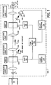
- Fig. 1 illustrates a laser beam intensity modulation system 100, which has been constructed according to the principles of the present invention.
- the current implementation is in an exposure system of an imagesetting device.
- the modulation system 100 is optically located between a laser 10, which generates a laser beam 11, and a scanning system 12 that raster scans the output beam 14 across a photosensitive media 16.
- the laser is a solid state laser such as a Nd:YAG laser.
- the input laser beam 11 is intensity modulated by system 100 before reaching the scanning system 12 as output beam 14.
- the laser beam intensity modulation system 100 includes at least two cascaded electro-optic modulators 110, 112, which are AOM's (acousto-optic modulators) in the preferred embodiment. These AOM's 110, 112 are arranged in the optical path 114 between the laser 10 and the photosensitive media 16 so that zero-order light, i.e. , the light that is transmitted directly through AOM's 110,112 in their unactivated or unmodulated state is transmitted along the optical path 114. The first-order, or diffracted, light that is generated when AOM's 110,112 are activated by an RF (radio-frequency) signal is steered out of the optical path 114 so that it does not reach the photosensitive media 16.
- AOM's acousto-optic modulators
- AOM's 110, 112 are controlled or modulated in response to a video signal from video source 116.
- the video signal is supplied to an amplifier 118, which generates a radio-frequency signal in AOM 110.
- the acoustic signal travelling through the AOM forms a periodic grating, which diffracts the input beam.
- the same video signal is provided to a second amplifier 120 to activate the second AOM 112.
- a variable delay 122 is provided on the signal path from the video source to the second amplifier 120.
- a delay controller 124 operates or controls the level of delay provided by the variable delay circuit 122.
- the delay controller detects the first-order light from the second AOM 112 using silicon cell detector 128, with an intervening optical density filter 130.
- Figs. 2A and 2B are plots of RF grating level, or level of modulation, in AOM's 110, 112 respectively, a function of a bit period at the respective optical beam locations in those AOM's. As illustrated, their operation is not perfectly synchronised. A timing error of t 1 is present, in which the second AOM 112 lags the first AOM 110.
- Fig. 2C shows the effect of this timing error in the first-order waveform from the second AOM 112. This effect is due to the fact that the second AOM is not modulating the optical beam precisely in synchronism with the first AOM. Such operation arises generally because the optical beams are not be focused at the same locations in the AOM's 110, 112.
- the propagation speed for the light between the AOM's is inconsequential and generally, the modulating RF signal can be distributed to AOM's simultaneously.
- the problem of improper synchronisation arises because the acoustic wave traverses relatively slowly across the AOM. It can require as long as one microsecond to establish the diffraction grating at the point where the focused beam traverses the crystal substrate.
- Factory calibration of the system minimises the timing errors by ensuring gross alignment of the AOM's, but not all error can be removed. Further, new phase or timing errors arise during the operation of the machine, both across its lifetime and across a given operating cycle, such as a day. They are generally caused by thermal effects, which can move the optical components out of their original positions even when properly calibrated at the factory.
- the silicon photocell 128 and delay controller 124 measure the average of the first order beam at the second AOM 112. This average is indicative of the timing error between the operation of the two AOM's 110, 112.
- the average varies as a function of the phase or timing error across the bit period.
- the delay controller 124 adjusts the variable delay 122 to minimise the average intensity of the waveform detected by the detector 128.
- This average is measured across 10's to 100's to 1000's of bit periods, depending on the implementation, by selecting the time constant of the silicon photocell, which inherently performs an integration operation on the detected signal.
- the timing error t 1 is minimised, or eliminated.
- Figs. 3A-3D show an analogous situation where the control is performed in response to the zero-order light from the second AOM.
- Figs. 3A and 3B illustrate another timing error in the synchronisation of the first AOM 110 and second AOM 112. This leads to a suboptimal rise time and fall time in the zero-order beam from the second AOM 112, see Fig 30.
- the average of the zero-order beam from the second AOM 112 is descriptive of the timing error between the two AOM's 110, 112.
- the timing error t 1 is minimised, or eliminated.
- Fig. 4 shows the implementation of the laser beam intensity modulation system 100 in an imagesetter.
- the laser beam 11 generated by laser 10 passes through a Faraday isolator 18 to an AOM focus lens 20.
- This lens ensures that the beam waist in AOM 110 is narrow to reduce any delay in the initiation of steering, to across the width of the beam, to further minimise the rise and fall times.
- the zero-order beam passes through a collimating lens 136 and a mask 138 before passing through a second focusing lens 140.
- This focusing lens 140 ensures a small beam waist in the second AOM 112.
- the beam After leaving the second AOM 112, the beam passes through another mask 142 and then a collimating lens 144. Two successive fold mirrors 146 and 148 redirect the beam to diverging lens 150 and an aperture 152. A final focusing array of lenses 154 directs the beam to a spin mirror 156, which scans the beam 14 over the photosensitive media 16 held on the internal drum surface.
- the spin mirror is powered by a spin motor 158 to raster scan the beam while moving along the drum axis 160.
- additional AOM's can be added to the cascade to obtain greater beam attenuation in the off-state.
- an additional variable delay and delay controller are used of each AOM to adjust its delay relative to the previous AOM's in the direction of light propagation.
Landscapes
- Engineering & Computer Science (AREA)
- Multimedia (AREA)
- Signal Processing (AREA)
- Physics & Mathematics (AREA)
- Optics & Photonics (AREA)
- Exposure And Positioning Against Photoresist Photosensitive Materials (AREA)
- Optical Modulation, Optical Deflection, Nonlinear Optics, Optical Demodulation, Optical Logic Elements (AREA)
- Facsimile Scanning Arrangements (AREA)
Applications Claiming Priority (2)
| Application Number | Priority Date | Filing Date | Title |
|---|---|---|---|
| US240983 | 1999-01-29 | ||
| US09/240,983 US6052216A (en) | 1999-01-29 | 1999-01-29 | Laser and beam intensity modulation system for imagesetting device |
Publications (2)
| Publication Number | Publication Date |
|---|---|
| EP1024650A2 true EP1024650A2 (de) | 2000-08-02 |
| EP1024650A3 EP1024650A3 (de) | 2003-09-17 |
Family
ID=22908730
Family Applications (1)
| Application Number | Title | Priority Date | Filing Date |
|---|---|---|---|
| EP00101929A Withdrawn EP1024650A3 (de) | 1999-01-29 | 2000-01-31 | System zur Intensitätsmodulation eines Laserstrahls für eine Bildsetzvorrichtung |
Country Status (2)
| Country | Link |
|---|---|
| US (1) | US6052216A (de) |
| EP (1) | EP1024650A3 (de) |
Cited By (1)
| Publication number | Priority date | Publication date | Assignee | Title |
|---|---|---|---|---|
| WO2004048945A1 (en) * | 2002-11-27 | 2004-06-10 | Optical Metrology Patents Limited | Apparatus for modulating a light beam |
Families Citing this family (10)
| Publication number | Priority date | Publication date | Assignee | Title |
|---|---|---|---|---|
| DE10062683A1 (de) | 2000-12-15 | 2002-06-20 | Heidelberger Druckmasch Ag | Mehrstrahl-Abtastvorrichtung |
| DE10309971A1 (de) * | 2003-03-07 | 2004-09-16 | Leica Microsystems (Schweiz) Ag | Operationsmikroskop mit einer Objektfeldbeleuchtung |
| KR100819872B1 (ko) * | 2006-05-17 | 2008-04-07 | 삼성전기주식회사 | 광 변조기 캘리브레이션 장치 |
| US9414498B2 (en) * | 2013-09-20 | 2016-08-09 | Coherent, Inc. | Via-hole drilling in a printed circuit board using a carbon monoxide laser |
| US9925620B2 (en) * | 2015-08-19 | 2018-03-27 | Coherent, Inc. | Carbon monoxide laser machining system |
| US10274806B2 (en) | 2015-11-06 | 2019-04-30 | Coherent, Inc. | Pulse-dividing method and apparatus for a pulsed carbon monoxide laser |
| US10423047B2 (en) | 2016-07-27 | 2019-09-24 | Coherent, Inc. | Laser machining method and apparatus |
| TWI892641B (zh) | 2019-01-31 | 2025-08-01 | 美商伊雷克托科學工業股份有限公司 | 光學系統 |
| DE102020000741A1 (de) | 2020-02-01 | 2021-08-05 | Hochschule Mittweida (Fh) | Vorrichtung zum schnellen Modulieren oder Schalten von Laserstrahlung eines Lasers mit hoher Leistung |
| EP4287422A1 (de) * | 2022-05-31 | 2023-12-06 | NKT Photonics A/S | Gepulstes lasersystem |
Family Cites Families (11)
| Publication number | Priority date | Publication date | Assignee | Title |
|---|---|---|---|---|
| US4213146A (en) * | 1978-03-24 | 1980-07-15 | Laser Video, Inc. | Scanning system for light beam displays |
| US4381887A (en) * | 1980-09-22 | 1983-05-03 | Xerox Corporation | Simplified acousto-optic deflector using electronic delays |
| DE3046584C2 (de) * | 1980-12-11 | 1984-03-15 | Dr.-Ing. Rudolf Hell Gmbh, 2300 Kiel | Optisch-mechanischer Abtaster |
| US4447134A (en) * | 1981-03-23 | 1984-05-08 | Litton Systems, Inc. | Grating signal system using zero order beam of acousto-optic modulator |
| US4443066A (en) * | 1981-06-17 | 1984-04-17 | Hazeltine Corporation | Acousto-optical apparatus for shifting a beam of light |
| US4473275A (en) * | 1982-01-25 | 1984-09-25 | Litton Systems, Inc. | Method and apparatus for improving the efficiency of an acousto-optic deflector |
| JPH0625828B2 (ja) * | 1986-04-07 | 1994-04-06 | 旭光学工業株式会社 | 走査光学系 |
| US4733252A (en) * | 1987-03-30 | 1988-03-22 | Xerox Corporation | Beam splitter for multibeam A/O modulators and printer systems |
| JPH0338614A (ja) * | 1989-07-05 | 1991-02-19 | Pioneer Electron Corp | 音響光学変調装置 |
| US5196949A (en) * | 1990-10-10 | 1993-03-23 | Xerox Corporation | Vestigial sideband scophony imaging modulator |
| US5623360A (en) * | 1991-12-12 | 1997-04-22 | Essex Corporation | Time delay beam formation |
-
1999
- 1999-01-29 US US09/240,983 patent/US6052216A/en not_active Expired - Fee Related
-
2000
- 2000-01-31 EP EP00101929A patent/EP1024650A3/de not_active Withdrawn
Cited By (1)
| Publication number | Priority date | Publication date | Assignee | Title |
|---|---|---|---|---|
| WO2004048945A1 (en) * | 2002-11-27 | 2004-06-10 | Optical Metrology Patents Limited | Apparatus for modulating a light beam |
Also Published As
| Publication number | Publication date |
|---|---|
| US6052216A (en) | 2000-04-18 |
| EP1024650A3 (de) | 2003-09-17 |
Similar Documents
| Publication | Publication Date | Title |
|---|---|---|
| EP0904559B1 (de) | Kurzwelliger gepulster laserabtaster | |
| US6437816B1 (en) | Laser exposure unit including plural laser beam sources differing in wavelengths | |
| US4201455A (en) | Laser-operated apparatus for data and signal recording | |
| CN101137927B (zh) | 用于多光束偏转和强度稳定的装置 | |
| US5309178A (en) | Laser marking apparatus including an acoustic modulator | |
| US20080137054A1 (en) | Image exposure apparatus | |
| US6052216A (en) | Laser and beam intensity modulation system for imagesetting device | |
| US4725855A (en) | Multi-beam laser printer with beam spacing detection during blanking time | |
| JPH0532734B2 (de) | ||
| CA2077813C (en) | Apparatus and method for spot position control in an output device employing a linear array of light sources | |
| JPH05215981A (ja) | 光走査装置 | |
| US5132834A (en) | Method of inputting signals to light modulator and simultaneous multi-beam type light modulating apparatus | |
| JPH0222616A (ja) | レーザ走査装置 | |
| US6552741B2 (en) | Optical scanning device, image scanning method and photographic processing device | |
| JPS6115119A (ja) | レ−ザプリンタ | |
| USRE36841E (en) | Multi-beam laser printer with beam spacing detection during blanking time | |
| JP2000019438A (ja) | 走査装置 | |
| JPH05131676A (ja) | 画像走査記録装置 | |
| JP3783586B2 (ja) | 露光装置 | |
| JPS60169820A (ja) | 画像走査記録装置の記録ヘツド | |
| JPS6145215A (ja) | レ−ザプリンタ | |
| JPS6115118A (ja) | レ−ザプリンタ | |
| JPH10157197A (ja) | 画像形成装置 | |
| JPH05328047A (ja) | 画像記録装置 | |
| JPH03132713A (ja) | 光ビーム走査装置 |
Legal Events
| Date | Code | Title | Description |
|---|---|---|---|
| PUAI | Public reference made under article 153(3) epc to a published international application that has entered the european phase |
Free format text: ORIGINAL CODE: 0009012 |
|
| AK | Designated contracting states |
Kind code of ref document: A2 Designated state(s): AT BE CH CY DE DK ES FI FR GB GR IE IT LI LU MC NL PT SE |
|
| AX | Request for extension of the european patent |
Free format text: AL;LT;LV;MK;RO;SI |
|
| PUAL | Search report despatched |
Free format text: ORIGINAL CODE: 0009013 |
|
| AK | Designated contracting states |
Kind code of ref document: A3 Designated state(s): AT BE CH CY DE DK ES FI FR GB GR IE IT LI LU MC NL PT SE |
|
| AX | Request for extension of the european patent |
Extension state: AL LT LV MK RO SI |
|
| RIC1 | Information provided on ipc code assigned before grant |
Ipc: 7H 04N 1/40 B Ipc: 7H 04N 1/00 A |
|
| STAA | Information on the status of an ep patent application or granted ep patent |
Free format text: STATUS: THE APPLICATION HAS BEEN WITHDRAWN |
|
| 18W | Application withdrawn |
Effective date: 20040320 |