EP1024005B1 - Tête d'impression à jet d'encre et procédé de fabrication - Google Patents
Tête d'impression à jet d'encre et procédé de fabrication Download PDFInfo
- Publication number
- EP1024005B1 EP1024005B1 EP00101638A EP00101638A EP1024005B1 EP 1024005 B1 EP1024005 B1 EP 1024005B1 EP 00101638 A EP00101638 A EP 00101638A EP 00101638 A EP00101638 A EP 00101638A EP 1024005 B1 EP1024005 B1 EP 1024005B1
- Authority
- EP
- European Patent Office
- Prior art keywords
- ink
- recording head
- jet recording
- plate
- ink jet
- Prior art date
- Legal status (The legal status is an assumption and is not a legal conclusion. Google has not performed a legal analysis and makes no representation as to the accuracy of the status listed.)
- Expired - Lifetime
Links
- 238000004519 manufacturing process Methods 0.000 title claims description 33
- 238000007789 sealing Methods 0.000 claims description 160
- 150000001875 compounds Chemical class 0.000 claims description 67
- 238000003466 welding Methods 0.000 claims description 40
- 238000000465 moulding Methods 0.000 claims description 10
- 238000001914 filtration Methods 0.000 claims description 5
- 239000012778 molding material Substances 0.000 claims description 4
- 229920002050 silicone resin Polymers 0.000 claims description 3
- 238000002844 melting Methods 0.000 claims description 2
- 230000008018 melting Effects 0.000 claims description 2
- 230000001419 dependent effect Effects 0.000 claims 1
- 239000000976 ink Substances 0.000 description 261
- 239000013464 silicone adhesive Substances 0.000 description 17
- 239000000428 dust Substances 0.000 description 11
- 238000005192 partition Methods 0.000 description 10
- 238000010586 diagram Methods 0.000 description 7
- 230000002093 peripheral effect Effects 0.000 description 7
- 238000000034 method Methods 0.000 description 6
- 238000012856 packing Methods 0.000 description 5
- 239000000853 adhesive Substances 0.000 description 4
- 230000001070 adhesive effect Effects 0.000 description 4
- 230000000694 effects Effects 0.000 description 4
- 229920005989 resin Polymers 0.000 description 3
- 239000011347 resin Substances 0.000 description 3
- 230000006866 deterioration Effects 0.000 description 2
- 229920001296 polysiloxane Polymers 0.000 description 2
- 230000002265 prevention Effects 0.000 description 2
- 239000000126 substance Substances 0.000 description 2
- KXGFMDJXCMQABM-UHFFFAOYSA-N 2-methoxy-6-methylphenol Chemical compound [CH]OC1=CC=CC([CH])=C1O KXGFMDJXCMQABM-UHFFFAOYSA-N 0.000 description 1
- 239000004925 Acrylic resin Substances 0.000 description 1
- 229920000178 Acrylic resin Polymers 0.000 description 1
- 244000043261 Hevea brasiliensis Species 0.000 description 1
- 239000011248 coating agent Substances 0.000 description 1
- 238000000576 coating method Methods 0.000 description 1
- 239000003086 colorant Substances 0.000 description 1
- 229920001971 elastomer Polymers 0.000 description 1
- 239000003822 epoxy resin Substances 0.000 description 1
- 238000001746 injection moulding Methods 0.000 description 1
- 238000003780 insertion Methods 0.000 description 1
- 230000037431 insertion Effects 0.000 description 1
- 238000005304 joining Methods 0.000 description 1
- 229920003052 natural elastomer Polymers 0.000 description 1
- 229920001194 natural rubber Polymers 0.000 description 1
- 229920001568 phenolic resin Polymers 0.000 description 1
- 239000005011 phenolic resin Substances 0.000 description 1
- 229920000647 polyepoxide Polymers 0.000 description 1
- 238000003825 pressing Methods 0.000 description 1
- 230000000717 retained effect Effects 0.000 description 1
- 239000005060 rubber Substances 0.000 description 1
- 239000012945 sealing adhesive Substances 0.000 description 1
- 238000005549 size reduction Methods 0.000 description 1
- 239000000758 substrate Substances 0.000 description 1
- 229920003051 synthetic elastomer Polymers 0.000 description 1
- 239000005061 synthetic rubber Substances 0.000 description 1
- 229920001169 thermoplastic Polymers 0.000 description 1
- 239000004416 thermosoftening plastic Substances 0.000 description 1
- 125000000391 vinyl group Chemical group [H]C([*])=C([H])[H] 0.000 description 1
- 229920002554 vinyl polymer Polymers 0.000 description 1
Images


Classifications
-
- B—PERFORMING OPERATIONS; TRANSPORTING
- B41—PRINTING; LINING MACHINES; TYPEWRITERS; STAMPS
- B41J—TYPEWRITERS; SELECTIVE PRINTING MECHANISMS, i.e. MECHANISMS PRINTING OTHERWISE THAN FROM A FORME; CORRECTION OF TYPOGRAPHICAL ERRORS
- B41J2/00—Typewriters or selective printing mechanisms characterised by the printing or marking process for which they are designed
- B41J2/005—Typewriters or selective printing mechanisms characterised by the printing or marking process for which they are designed characterised by bringing liquid or particles selectively into contact with a printing material
- B41J2/01—Ink jet
- B41J2/135—Nozzles
- B41J2/14—Structure thereof only for on-demand ink jet heads
-
- B—PERFORMING OPERATIONS; TRANSPORTING
- B29—WORKING OF PLASTICS; WORKING OF SUBSTANCES IN A PLASTIC STATE IN GENERAL
- B29C—SHAPING OR JOINING OF PLASTICS; SHAPING OF MATERIAL IN A PLASTIC STATE, NOT OTHERWISE PROVIDED FOR; AFTER-TREATMENT OF THE SHAPED PRODUCTS, e.g. REPAIRING
- B29C45/00—Injection moulding, i.e. forcing the required volume of moulding material through a nozzle into a closed mould; Apparatus therefor
- B29C45/17—Component parts, details or accessories; Auxiliary operations
- B29C45/26—Moulds
- B29C45/2628—Moulds with mould parts forming holes in or through the moulded article, e.g. for bearing cages
-
- B—PERFORMING OPERATIONS; TRANSPORTING
- B41—PRINTING; LINING MACHINES; TYPEWRITERS; STAMPS
- B41J—TYPEWRITERS; SELECTIVE PRINTING MECHANISMS, i.e. MECHANISMS PRINTING OTHERWISE THAN FROM A FORME; CORRECTION OF TYPOGRAPHICAL ERRORS
- B41J2/00—Typewriters or selective printing mechanisms characterised by the printing or marking process for which they are designed
- B41J2/005—Typewriters or selective printing mechanisms characterised by the printing or marking process for which they are designed characterised by bringing liquid or particles selectively into contact with a printing material
- B41J2/01—Ink jet
- B41J2/135—Nozzles
- B41J2/16—Production of nozzles
- B41J2/1621—Manufacturing processes
- B41J2/1623—Manufacturing processes bonding and adhesion
-
- B—PERFORMING OPERATIONS; TRANSPORTING
- B41—PRINTING; LINING MACHINES; TYPEWRITERS; STAMPS
- B41J—TYPEWRITERS; SELECTIVE PRINTING MECHANISMS, i.e. MECHANISMS PRINTING OTHERWISE THAN FROM A FORME; CORRECTION OF TYPOGRAPHICAL ERRORS
- B41J2/00—Typewriters or selective printing mechanisms characterised by the printing or marking process for which they are designed
- B41J2/005—Typewriters or selective printing mechanisms characterised by the printing or marking process for which they are designed characterised by bringing liquid or particles selectively into contact with a printing material
- B41J2/01—Ink jet
- B41J2/135—Nozzles
- B41J2/16—Production of nozzles
- B41J2/1621—Manufacturing processes
- B41J2/1637—Manufacturing processes molding
-
- B—PERFORMING OPERATIONS; TRANSPORTING
- B41—PRINTING; LINING MACHINES; TYPEWRITERS; STAMPS
- B41J—TYPEWRITERS; SELECTIVE PRINTING MECHANISMS, i.e. MECHANISMS PRINTING OTHERWISE THAN FROM A FORME; CORRECTION OF TYPOGRAPHICAL ERRORS
- B41J2/00—Typewriters or selective printing mechanisms characterised by the printing or marking process for which they are designed
- B41J2/005—Typewriters or selective printing mechanisms characterised by the printing or marking process for which they are designed characterised by bringing liquid or particles selectively into contact with a printing material
- B41J2/01—Ink jet
- B41J2/17—Ink jet characterised by ink handling
- B41J2/175—Ink supply systems ; Circuit parts therefor
- B41J2/17503—Ink cartridges
- B41J2/1752—Mounting within the printer
Definitions
- the present invention relates to an ink jet recording head for ejecting ink supplied from an ink tank in the form of ink drops, and a method of manufacturing the same.
- a recording head of an ink jet recording head is composed of a head body for ejecting ink in the form of ink drops and an ink cartridge containing ink to be supplied to the head body.
- the recording head has an ink supply needle, and the ink cartridge has an ink supply hole. Ink is supplied to the head body through the ink supply needle that is inserted into the ink supply hole.
- a head body 1 for ejecting ink drops in accordance with a print signal is mounted on the lower side of a head holder 10.
- a cartridge case 12 for receiving an ink cartridge 2 is provided on the upper side of the head holder 10.
- a positioning protrusion 13 is formed on the lower side of the ink cartridge 2, and an ink supply hole 4 is formed under the positioning protrusion 13. The opening of the ink supply hole 4 is sealed with a film 14 till the ink cartridge 2 is set to the recording head.
- the ink cartridge 2 includes a plurality of ink chambers 15. As shown in Fig. 16 , for example, the ink cartridge includes four ink chambers containing color inks of cyan, magenta, yellow and black. A plurality of ink supply holes 4 are provided in the ink cartridge 2. Specifically, the ink supply hole 4 is provided for each ink chamber 15 (viz., each color). Four ink supply needles 3 are also provided for those colors, respectively.
- Fig. 16 shows the recording head before the ink cartridge 2 is set to the head.
- each ink supply needle 3 is shaped to be conical so that it can break through a film of the ink supply hole 4.
- Ink introducing holes 6 are vertically formed in a slanted surface 8 of the tip of the needle.
- a first ink passage 5, which communicates with the ink introducing holes 6, is formed in the ink supply needle 3.
- Second ink passages 7 for supplying ink to the head body 1 are formed in the head holder 10.
- a filter 9 for filtering ink supplied from the ink cartridge 2 is provided at the entrance of each second ink passage 7.
- the second ink passages 7 are obliquely extended toward the head body 1 centered (see Fig. 16 ).
- the tip of the ink supply needle 3 breaks through the film 14 which sealingly closes the ink supply hole 4 of the ink cartridge 2 and, the ink supply needle 3 is inserted into the ink supply hole 4. Then, in the recording head, ink is supplied from the ink cartridge 2 into the head body 1, through the ink introducing holes 6 of the ink supply needle 3 and the first and second ink passages 5 and 7.
- the recording head together with the ink cartridge 2, is carried on a carriage (not shown), and reciprocatively moved across a recording sheet by the carriage.
- Ink to be consumed is supplied from the ink cartridge 2 to the head body 1 via the ink supply needle 3 in a replenishing manner.
- the recording head ejects ink drops through its nozzle orifices toward the recording sheet, thereby effecting a print.
- the second ink passages 7 are obliquely extended to the head body 1.
- the second ink passages 7 are slanted, there is a limit in reducing the height of the recording head per se . For this reason, the related recording head cannot meet the demand of size reduction in the recent ink jet recording heads.
- EP 0 315 417 discloses a recording head that forms the basis for the preamble of claim 1.
- JP 09 300 646 discloses a recording head according to the preamble of claim 1.
- an object of the present invention is to provide an ink jet recording head which is easy in working and assembling, low in cost, reduced in size, and is substantially free from entry of air bubbles into passages.
- an ink jet recording head comprising:
- a portion forming the ink supply channel of the recording head is composed of two types of plate-like members. Therefore, the recording head may be remarkably reduced in size when comparing with the related one in which the ink supply channel is formed by use of slanted passage.
- the sealing plate is welded to the channel forming plate, so that there is less chance that dust and the like enter the ink supply channel. Further, the slanted passage requiring intricate work is not used, and the assembling is easy and manufacturing cost is low.
- the assembling of the recording head is easy and hence it is easy to make automating of the assembling process of the recording head. Welding residual substances are hard to be produced, while the ultrasonic welding is unlikely to yield them. Chance that dust and others enter the ink supply channel is further lessened.
- the slanted surface being gradually slanted downward to the groove is provided.
- a gap on a portion of the slanted surface that is formed in a state that the surface of the channel forming plate is sealed with the sealing plate, is satisfactorily small. Accordingly, it holds a sealing compound satisfactorily, and it is hard to flow over the gap.
- the recording head is substantially free from the problem of the flow of the sealing compound into the ink supply channel, which is unavoidable in the related recording head. Further, the ink ejection trouble arising from attachment of air bubbles to the sealing compound is also solved.
- the channel forming plate may integrally include a holder member for holding the ink tank, and the sealing plate is bonded to the holding member.
- the working and assembling are easy, and cost to manufacture is reduced.
- the opened side of the respective grooves are sealed by bonding the sealing plate to the holding member.
- the channel forming plate may be provided as an independent member.
- the working and assembling are easy, and cost to manufacture is reduced.
- the channel forming plate may define at least a bottom portion and side walls of the respective grooves.
- the grooves are formed by the channel forming plate and the sealing plate.
- the channel forming plate includes through holes which respectively define side walls of the grooves.
- the grooves are formed by the channel forming plate, the sealing plate and a member for sealing one opening side of the through hole to define a bottom portion of the grooves.
- One longitudinal end portion of the respective grooves may be communicated with the ink tank, and the other end portions are communicated with the head body.
- the size of head body can be remarkably reduced irrespective of the size of ink tanks due to the arrangement of the grooves.
- the end portions of the respective grooves communicated with the head body may be converged.
- the size of head body can be remarkably reduced irrespective of the size of ink tanks.
- Plural kinds of ink may be ejected from the head body, and the grooves may be provided so as to be associated with the ink kind.
- ink jet recording head plural kinds of ink can be supplied to the head body through the grooves and ejected therefrom.
- Sealing compound is provided on the channel forming plate at least around the grooves.
- the grooves of the channel forming plate is sealed with sealing compound. Accordingly, the ink supply channel is reliably formed, and there is less chance that dust and the like enter the channel.
- the channel forming plate and the sealing plate may be fastened together with the sealing compound being located therebetween.
- the groove of the channel forming plate is sealed with sealing compound. Accordingly, the ink supply channel is reliably formed, and there is less chance that dust and the like enter the channel.
- the welding pin may be provided at a portion surrounding the grooves.
- the mounting structure of the plate and the channel forming plate is hard to be unsteady and ink leakage is unlikely to occur.
- a plurality of welding pins may be provided so as to surround the grooves.
- the mounting structure of the plate and the channel forming plate is hard to be unsteady and ink leakage is unlikely to occur.
- a filter for filtering ink supplied from the ink tank may be provided.
- the ink supply channel guides ink having passed through the filter to the head body.
- the sealing compound may be made of silicone resin.
- the sealing compound In the ink jet recording head, the sealing compound is hard to be deteriorated and aged by ink, and the ink leakage occurs less frequently.
- a stepped portion on which sealing compound is to be applied may be formed on an outer periphery of the wall portion.
- the work to apply the sealing compound to the stepped portion is easy.
- the overflow of the sealing compound may be prevented by reducing the amount of sealing compound applied. In this case, if the amount of it is excessively reduced, control of the application of the sealing compound is impossible. In an extreme case, the supply of the sealing compound is interrupted, resulting in poor sealing.
- the sealing compound is applied to the stepped portion. Therefore, the amount of the sealing compound effectively contributing to the sealing is reduced when the sealing is effected by the sealing plate. For this reason, the overflow of the sealing compound can effectively be prevented without excessively reducing the amount of the sealing compound applied.
- the control of the amount of the sealing compound applied is also easy, and poor sealing is not caused.
- a slope of the slanted face may be selected to be preferably within 5/1000 to 200/1000.
- the gap on a portion of the slanted surface that is formed in a state that the surface of each of the channel forming plate is sealed with the sealing plate is satisfactorily small. Accordingly, if air bubbles attach to the sealing compound, its amount is considerably small. Removal of the air bubbles from the sealing compound is difficult, thereby preventing poor ejection trouble.
- a flat portion may be provided between the stepped portion and the slanted surface.
- a corner demarcating the stepped portion and the flat portion may be removed to form a tapered surface.
- the sealing compound applied to the stepped portion when the sealing compound applied to the stepped portion is held down by the sealing plate and spreads to the flat portion, the sealing compound stands on the tapered surface, and there is no excessive flow of the sealing compound to the flat portion. Therefore, prevention of the overflow of the sealing compound into the ink supply channel is further ensured.
- the sealing plate may be provided with ink supply holes for supplying ink from the respective ink supply channels to the head body.
- the ink supply holes are bored in the sealing plate obliquely such that an interval of openings of the respective holes on the side facing the channel forming plate is longer than an interval of openings of the respective holes on the side facing the head body.
- the interval of the openings of the respective holes on the side facing the channel forming plate is set to be equal to that of ink supply passages of the head body, the interval of the openings of the respective holes on the side facing the head body becomes longer than that.
- the grooves may be defined by a wall portion standing erect on the channel forming plate.
- the width of the wall portion is 1.0mm or longer over the entire circumference of the grooves.
- the respective openings of the ink supply holes facing the head body may be circular in shape.
- the openings of the ink supply holes of the resultant plate are simple in shape, the manufacturing cost is not high, the sealing performance is not degraded, and air bubbles being caught in the passages less happens. If the ink supply holes obliquely passing through the plate are formed by use of normal pins circular in cross section, the openings of the ink supply holes are elliptical. Therefore, it is necessary to shape the openings of the ink supply pipes of the head body to be elliptical, and hence to shape the packing applied thereto to be also elliptical.
- the elliptical member needs to be used for the other member.
- the manufacturing cost of the overall device is increased. Further, the sealing is deteriorated, and air bubbles are easy to be caught.
- the openings of the ink supply holes of the sealing plate are circular. Therefore, there is no need of making the elliptical openings of the ink supply pipes and the elliptical packing applied to those. Consequently, the manufacturing cost is low, good sealing is secured, and air bubbles are little caught in the passages.
- a stepped portion is formed around the respective openings of the ink supply holes facing the channel forming plate.
- the ink jet recording head of the invention may be manufactured at low cost and in an easy manner.
- Both tip ends of the respective supply hole forming pins abutting against the inner face of the mold may be circular in shape.
- the openings of the ink supply holes of the resultant plate are simple in shape, the manufacturing cost is not high, the sealing performance is not degraded, and air bubbles being caught in the ink supply channels less happens.
- One end portion of the respective supply hole forming pins which corresponds to the opening of the ink supply hole facing the channel forming plate is configured to have a large diameter.
- the stepped portion may be formed around the opening of each ink supply hole in a relatively simple manner. With provision of the stepped portion, the sealing performance is little degraded.
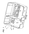
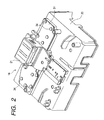
- Figs. 1 and 2 show a first example of a first ink jet recording head 18.
- the ink jet recording head 18 includes a box-like cartridge case 20 opened at the upper side thereof, and a head body 21 mounted on the lower side of the cartridge case 20.
- the cartridge case 20 contains a partition wall 22.
- the partition wall is located at a position closer to one side of the cartridge case 2 with respect to the center thereof, whereby the inner space to the cartridge case is partitioned into two accommodating chambers 23a and 23b for accommodating ink cartridges.
- Three ink supply needles 24a stand erect on the bottom of the accommodating chamber 23a, larger in size (located on the right side in Fig. 1 ).
- One ink supply needle 24b stands erect on the bottom of the accommodating chamber 23b, small in size (located on the left side in Fig. 1 ).
- a first ink cartridge (not shown), which is filled with three color inks of, for example, cyan, magenta and yellow, is accommodated in the large accommodating chamber 23a.
- a second ink cartridge (not shown), which is filled with black in, is accommodated in the large accommodating chamber 23b.
- the tips of the ink supply needles 24a and 24b are conical in shape.
- a number of ink introducing holes 27 are vertically formed in the slanted surface of the tip of each ink supply needles.
- Each of the ink introducing holes 27 communicates with a first ink supply passage 28 vertically extending within each of the ink supply needles 24a and 24b.
- Second ink supply passages 39 which vertically extend and communicate with the first ink supply passages 28, are formed in locations of the cartridge case 20, which correspond to the ink supply needles 24a and 24b.
- a filter 38 for filtering ink supplied from the ink cartridge is provided at an incoming part of each second ink supply passage 39 (where is close to the each of the ink supply needles 24a and 24b).
- ellipsoidal channel forming plates 29 are integrally formed on the lower side of the cartridge case 20, and grooves 30 that communicate with the second ink supply passages 39 are respectively formed in the surfaces of those channel forming plates 29.
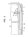
- the portions of the grooves 30 are formed in channels 32 such that the surfaces of the channel forming plates 29 are sealingly coupled to a plate (sealing plate) 31 by use of silicone (sealing compound) which is hard to be deteriorated and aged by ink ( Fig. 3 ).
- the channels 32 (grooves 30) are extended to the central portion of the cartridge case 20.
- Ink supply holes 33a and 33b for supplying ink from the channels 32 to the head body 21 are bored at locations corresponding to the tips of the channels 32 of the plate 31 in the direction perpendicular to the surface of the plate 31.
- one longitudinal end portion of the respective grooves 30 are communicated with the ink cartridge through the second ink supply passages 39, and the other end portions are communicated with the head body 21 through at least one ink supply hole 33a.
- the respective grooves 30 are arranged such that the end portions facing the second ink supply passages 39 are separated from each other in comparison with the end portions facing the ink supply hole 33a. In other words, the end portions of the grooves communicated with the head body are converged.
- a structure of mounting the plate 31 onto the channel forming plates 29 will be described in detail.
- a plurality of welding pins 34 (sixteen number of welding pins in the instance of Fig. 4 ) stand erect on the lower side of the channel forming plates 29, while surrounding the four grooves 30. Plural number of welding pins 34 are located around each of the grooves 30.
- the welding pins 34 are provided at seven locations around the leftmost groove 30-1, for example, (the corresponding ones 30 and 34 are painted out in the figure, for ease of understanding). As shown in Fig. 5B , the welding pins 34 are provided at four locations around the second groove 30-2 counted from the left end in the figure. Similarly, as sown in Figs. 5C and 5D , the welding pins 34 are provided at four and six locations around the third and fourth grooves 30-3 and 30-4, counted from the left in the figures. Thus, the welding pins 34 are provided at a plurality of locations around one groove 30, so that if an external force is applied to the plate 31, the mounting structure is hard to be unsteady and ink leakage is unlikely to occur.
- Through holes 35 into which the welding pins 34 are to be inserted are bored at locations of the plate 31, which, respectively, correspond to the welding pins 34.
- the plate 31 is mounted on the channel forming plates 29 in a manner that the welding pins 34 are inserted into those through holes 35, and in this state, the tips of the welding pins 34 are welded and crushed (see Fig. 2 ).
- the recording head may be assembled in the following way, for example.
- the cartridge case 20 is fixed in a state that its bottom side is directed upward.
- Silicone adhesive 36 is applied to portions around the grooves 30 of the channel forming plates 29.
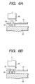
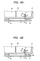
- the plate 31 is positioned on the channel forming plates 29, and as shown in Fig. 6 , welding pins 34 are inserted into through holes 35.
- the tips of the welding pins 34 are pressed with heated caulking pins 45, so that the tips of the welding pins 34 are welded and crushed. Thereafter, the pressing by the caulking pins 45 are removed, and those welding pins are cooled down.
- the welding pins 34 are solidified, so that the plate 31 is fastened to the channel forming plates 29.
- reference numeral 37 represents a support rib for supporting the plate 31.
- a portion forming the channels 32 is composed of two types of plate-like members, the channel forming plates 29 and the plate 31. Therefore, the recording head 18 may be remarkably reduced in size when comparing with the related one in which the channels are formed by use of slanted holes.
- the size of the head body 20 can be remarkably reduced irrespective with the size of the ink cartridge.
- the assembling of the recording head is easy and hence it is easy to make automating of the assembling process of the recording head. Its manufacturing cost is low.
- the channels 32 are sealed with the sealing adhesive. For this reason, there is less chance that dust and others enter the channels 32.
- the channel forming plate 29 is integrally formed on the bottom face of the cartridge case 20, however, the channel forming plate 29 and the cartridge case 20 may be provided as separated members.
- a channel forming plate 29A which defines a bottom portion and side walls of the grooves 30 is bonded to the bottom face of the cartridge case 20, and the opened side of the grooves are sealed by the plate 31.
- a channel forming plate 29B having through holes which define side walls of the grooves 30 is bonded to the bottom face of the cartridge case 20, and the opened side of the grooves are sealed by the plate 31.
- a channel forming substrate 29C is provided as an independent member and silicone adhesive 36 are applied to peripheral portion of the grooves 30 so that the opened side of the grooves 30 are sealed by the cartridge case 20.
- the cartridge case 20 serves as the sealing plate.
- a member 29D having through holes, a member such as the plate 31 for sealing opened side of the through holes to define a bottom portion of the grooves 30 are provided as separated members, and a channel forming plate are made by bonding the member 29D and the plate 31 with each other.
- Fig. 9 is a cross sectional view for explaining the sealing portions between a channel forming plate and a plate, which form an embodiment of the present invention.
- This embodiment is another joining structure of the channel forming plates 29 and the plate 31, and the remaining portions are similar to those of the first ink jet recording head.
- the sealing portion between the channel forming plates and the plate will be described in detail.
- each channel forming plate 29 is configured such that the peripheral portion of its groove 30, or the surface of the partition wall around the groove 30, which faces the sealing plate, is a slanted surface 48 being gradually slanted downward to the groove 30 (down slope).
- a step 49 which forms a recess to be coated with silicone adhesive 36, is provided outside the peripheral edge of the channel forming plate 29, or the slanted surface 48 of the partition wall around the grooves 30.
- a flat portion 51 is present between the step 49 and the slanted surface 48. A corner demarcating the step 49 and the flat portion 51 is removed to form a tapered surface 50.
- a slope of the slanted surface 48 is selected to be preferably within 5/1000 to 200/1000. Where the slope is smaller than 5/1000, a gap on a portion of the slanted surface 48 that is formed in a state that the surface of each of the channel forming plates 29 is sealed with the plate 31, is too small. Accordingly, it cannot hold the silicone adhesive 36 satisfactorily, and the silicone adhesive 36 is easy to flow over the gap. Where it exceeds 200/1000, the gap of the portion of the slanted surface 48 is too large, large air bubbles attach to the silicone adhesive 36.
- the recording head may be assembled in the following way, for example.
- the cartridge case 20 is fixed in a state that its bottom side is directed upward.
- Silicone adhesive 36 is applied to portions of the steps 49 of the partition walls.
- the plate 31 is positioned on the channel forming plates 29 and as shown in Fig. 10B , the plate 31 is placed on the surface of each channel forming plate 29. Further, as shown in Fig. 6A , the welding pins 34 of the cartridge case 20 are inserted into the through holes 35 of the plate 31. Then, the tips of the welding pins 34 are pressed with the heated caulking pins 45, so that as shown in Fig. 6B , the tips of the welding pins 34 are welded and crushed. As a result, the plate 31 is fastened to the channel forming plates 29.
- the silicone adhesive 36 applied to the step 49 is spread from the flat portion 51 up to the portion of the slanted surface 48, so that the portions of the grooves 30 are sealed to form the channels 32.
- the silicone adhesive 36 applied to the step 49 is held back with the plate 31 since the tapered surface 50 is formed at the corner demarcating the step 49 and the flat portion 51.
- the silicone adhesive 36 stands on the tapered surface 50, and there is no excessive flow of the silicone adhesive to the flat portion 51. Therefore, the silicone adhesive 36 is hard to flow out and into the channels 32.
- the portion forming the channels 32 is formed with the channel forming plates 29 and the plate 31. Therefore, the recording head is reduced in size and its assembling is easy, and its manufacturing cost is reduced.
- the surface, which faces the sealing plate, of the partition wall around each groove 30 of the channel forming plates 29 is a slanted surface 48 being gradually slanted downward toward the groove 30.
- a gap is formed on a portion of the slanted surface 48 in a state that the surface of each of the channel forming plates 29 is sealed with the plate 31.
- the silicone adhesive 36 is retained in each gap, so that it is hard to flow out of the gap and into the channels 32.
- a corner demarcating the step 49 and the flat portion 51 is removed to form a tapered surface 50.
- a rounded tapered surface may be formed thereat in place of it. Also in those cases, the advantageous effects similar to those mentioned above may be obtained.
- Fig. 11 is an enlarged view for explaining a channel forming plate and a plate which form a further embodiment
- Fig. 12 show plan and cross sectional views of a main portion of the plate.
- This embodiment is concerned with another ink supply hole communicatively interconnecting each passage 32 and the head body, and the remaining structure of it is substantially the same as of the second ink jet recording head.
- a surface of each channel forming plate 29 is configured such that its surface, which faces the sealing plate, of the partition wall around the groove 30, is a slanted surface 48 being gradually slanted downward to the groove 30.
- a step 49, which forms a recess to be coated with silicone adhesive 36, is provided outside the slanted surface 48 of the partition wall around the grooves 30.
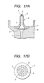
- the opening of each of the ink supply holes 33a is circular when viewed from the top and bottom thereof, as shown in Figs. 10A and 10C . Accordingly, it is elliptical when viewed in the direction (arrow direction C in Fig.
- a stepped portion 25 which is elliptical as viewed from top, is formed around each ink supply hole 33a of the plate 31.
- the stepped portion 25 is approximately 10 to 30 ⁇ m in depth.
- Ink supply holes 33b which are each located apart from the end of the channels 32, are formed in the plate 31 in the direction perpendicular to the surface of the plate 31 (see Fig. 3 ).
- the width D of the channel forming plate 29 is preferably 1.0mm or longer over the entire circumference of the groove 30. If the width D is shorter than 1.0mm, there is a fear that sealing is poor or sealing compound flows out and into the passage 32. Practically, the width D is within approximately 2.0mm in order to avoid the increase of the size of the recording head 18.
- a plate 31 used for the recording head 18 of the embodiment is formed by one-piece molding process such as injection molding process.
- ink supply holes 33a to be formed passing through the plate 31 are formed in the plate by use of draw pins 70 (supply hole forming pins) as shown in Fig. 13 .
- the draw pins 70 are each formed by applying predetermined working to the end portion of a pin being circular in cross section.
- the draw pin 70 is disposed at an angle ( ⁇ in the figure) at which the ink supply holes 33a pass through the plate, and in this state its end portion of a predetermined length measured from its tip is shaped to be circular in cross section (see Fig. 13C ).
- the end face of the draw pin 70 which is to be in contact with the mold face, is formed to be circular (see Fig. 13B ).
- a length L of the worked end portion of the draw pin is somewhat shorter than the thickness of the plate 31, and its root side portion is formed to have a large diameter.
- the draw pins 70 are used in combination with molds 72a and 72b having a molding space 71 in which a plate 31 is formed.
- Slide holes 73 are formed in the first mold 72a, while being each inclined, with respect to the mold face, at an angle ⁇ at which an ink supply hole 33a passes through the plate.
- the draw pins 70 are slidably inserted into those slide holes 73, respectively. In this state, the end faces of the draw pins 70 are brought into contact with the mold face (the face corresponding to the plate 31) of the second mold 72b.
- the plate 31 is formed by use of the molds 72a and 72b and the draw pins 70 in the following manner.
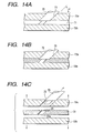
- Fig. 14A in state that the draw pins 70 are set in the first mold 72a, the first mold 72a and the second mold 72b are clamped.
- Fig. 14B the molding space 71 is filled with molten resin and cooled to be solidified.
- Fig. 14C the draw pins 70 are slid in the root side direction to pull them from the molded product.
- the first mold 72a and the second mold 72b are vertically opened. In this way, the plate 31 is produced. Portions of the plate from which the draw pins 70 were pulled out are ink supply holes 33a.
- the openings of the ink supply holes 33a are also circular in shape.
- the length L of the worked end portion of each of the draw pins 70 is somewhat shorter than the thickness of the plate 31, and its portion closer to the mold face of the first mold 72a is configured to have a large diameter. Because of this, a stepped portion 25 is formed around the peripheral edge of each ink supply hole.
- the cartridge case 20 is fixed in a state that its bottom 33a is directed upward.
- Silicone adhesive 36 is applied to the steps 49 around the grooves 30 of the channel forming plates 29.
- the plate 31 is positioned on the channel forming plates 29, and the plate 31 is placed on the surfaces of the channel forming plates 29, and the welding pins 34 of the cartridge case 20 are inserted into the through holes 35 of the plate 31, respectively.
- the tips of the welding pins 34 are pressed with heated caulking pins 45, so that the tips of the welding pins 34 are welded and crushed.
- the plate 31 is fastened to the channel forming plates 29.
- the recording head 18 may be manufactured at low cost. Since the openings of the ink supply holes 33a of the resultant plate 31 are circular, the manufacturing cost is not high, the sealing performance is not degraded, and air bubbles being caught in the passages less happens. Specifically, if the ink supply holes 33a obliquely passing through the plate are formed by use of normal pins circular in cross section, the openings of the ink supply holes are elliptical. On the other hand, the openings of the ink supply holes 33a of the plate 31 manufactured by the manufacturing method mentioned above are circular. Therefore, there is no need of making elliptical the openings of the ink supply pipes 16 and packing applied to those. Consequently, the manufacturing cost is low, good sealing is secured, and air bubbles are little caught in the passages.
- the length L of the worked end portion of each of the draw pins 70 is somewhat shorter than the thickness of the plate 31, and its portion closer to the mold face of the first mold 72a is configured to have a large diameter, and a stepped portion 25 is formed around the peripheral edge of each ink supply hole. Therefore, even if the working accuracy is not satisfactory, there is less chance that protrusions are formed along the circumferential edge of each of the openings of the ink supply holes 33a, and hence good sealing performance is secured.
- silicone adhesive 36 is used for the sealing compound in the above-mentioned embodiments, it may be replaced with thermoplastic adhesive containing acrylic resin or vinyl resin as a main component, heat-hardening resin adhesive containing phenolic resin or epoxy resin as a main component, rubber adhesive containing natural rubber or synthetic rubber as a main component or others.
- the advantageous effects as of the above-mentioned embodiments are obtained. If the adhesive used is good in sealing performance and adhesion, the channel forming plates and the sealing plate may be fastened together not using the welding.
- a portion forming the ink supply channels of the recording head is composed of two types of plate-like members. Therefore, the recording head may be remarkably reduced in size when comparing with the related one in which the passages are formed by use of slanted holes.
- the sealing plate is welded to the channel forming plates with the sealing plate being interposed therebetween. Therefore, there is less chance that dust and the like enter the channels. Further, the slanted holes requiring intricate work are not used, and the assembling is easy and manufacturing cost is low.
- the ink jet recording head which is constructed such that the welding of the sealing plate to the channel forming plates is performed in a manner that welding pins standing erect on the channel forming plates are inserted into insertion holes of the sealing plate, and welded and deformed, the assembling of the recording head is easy and hence it is easy to make automating of the assembling process of the recording head. Welding residual substances are hard to be produced, while the ultrasonic welding is unlikely to yield them. Chance that dust and others enter the channels is further lessened.
- the ink jet recording head which is constructed such that the welding pins are formed at portions surrounding the grooves of the channel forming plates, respectively, or the welding pins are formed at a plurality of positions around each the groove of the channel forming plates, if an external force is applied to the sealing plate, the mounting structure of the plate and the channel forming plates is hard to be unsteady and ink leakage is unlikely to occur.
- the ink jet recording head which further comprises a filter for filtering ink supplied from the ink tank, and in which the passages guide ink having passed through the filter to the head body, no dust enter the passages which rejects the presence of dust and the like, and the recording head is extremely effective.
- the sealing compound is silicone resin
- the sealing compound is hard to be deteriorated and aged by ink, and the ink leakage occurs less frequently.
- the surface of the partition wall around each the groove, which faces the sealing plate is a slanted surface being gradually slanted downward to the groove. Therefore, a gap on a portion of the slanted surface that is formed in a state that the surface of each of the channel forming plates is sealed with the sealing plate, is satisfactorily small. Accordingly, it can hold the sealing compound satisfactorily, and it is hard to flow over the gap.
- the recording head is substantially free from the problem of the flow of the sealing compound into the passages, which is unavoidable in the related recording head. Further, the ink ejection trouble arising from attachment of air bubbles to the sealing compound is also solved.
- the work to apply the sealing compound to the step is easy.
- the overflow of the sealing compound may be prevented by reducing the amount of sealing compound applied. In this case, if the amount of it is excessively reduced, control of the application of the sealing compound is impossible. In an extreme case, the supply of the sealing compound is interrupted, resulting in poor sealing.
- the sealing compound is applied to the step. Therefore, the amount of the sealing compound effectively contributing to the sealing is reduced when the sealing is effected by the sealing plate. For this reason, the overflow of the sealing compound can effectively be prevented without excessively reducing the amount of the sealing compound applied.
- the control of the amount of the sealing compound applied is also easy, and poor sealing is not caused.
- the gap on a portion of the slanted surface that is formed in a state that the surface of each of the channel forming plates is sealed with the sealing plate is satisfactorily small. Accordingly, if air bubbles attach to the sealing compound, its amount is considerably small. Removal of the air bubbles from the sealing compound is difficult, thereby preventing poor ejection trouble.
- a pitch of the ink supply holes on the side where the head body is present is set to be equal to that of ink supply pipes of the head body, a pitch of the ink supply holes on the side where the passages are present is longer than that. Accordingly, a sufficient space is present, so that a sufficient width of the channel forming plate is secured in a portion of the channel forming plate corresponding to the ink supply hole.
- the sealing compound is applied thereto. If the sealing compound flows out and into the passages, the problems of attachment of air bubbles arise.
- the ink jet recording head may be manufactured at low cost and in an easy manner.
- the end face of each the supply hole forming pin which is brought into contact with a mold face corresponding to the surface of the sealing plate, is circular in shape
- the openings of the ink supply holes of the resultant plate are simple in shape, the manufacturing cost is not high, the sealing performance is not degraded, and air bubbles being caught in the passages less happens.
- the openings of the ink supply holes are elliptical. Therefore, it is necessary to shape the openings of the ink supply channels of the head body to be elliptical, and hence to shape the packing applied thereto to be also elliptical. Thus, the elliptical member needs to be used for the other member. The manufacturing cost of the overall device is increased. Further, the sealing is deteriorated, and air bubbles are easy to be caught. On the other hand, in the invention, the openings of the ink supply holes of the sealing plate are circular. Therefore, there is no need of making the elliptical openings of the ink supply channels and the elliptical packing applied to those. Consequently, the manufacturing cost is low, good sealing is secured, and air bubbles are little caught in the passages.
- a supply hole forming pins are each configured such that its end portion smaller than the thickness of the sealing plate has a circular shape in its cross section parallel to the mold face corresponding to the surface of the sealing plate, there is substantially eliminated the deterioration of the sealing at the openings of the ink supply holes.
- a stepped portion is formed around the peripheral edge of each ink supply hole. Therefore, even if the working accuracy is not satisfactory, there is less chance that protrusions are formed along the circumferential edge of each of the openings of the ink supply holes, and hence good sealing performance is secured.
Claims (18)
- Tête d'impression à jet d'encre (18) comprenant :un corps de tête (21) à partir duquel des gouttes d'encre sont éjectées ;une plaque de formation de canal (29) dotée de rainures ;une plaque d'étanchéité (31) pour réaliser l'étanchéité de chaque côté ouvert des rainures afin de former un canal d'alimentation d'encre pour amener l'encre d'un réservoir d'encre au corps de tête, caractérisée en ce que :une broche de soudage (34) est prévue sur la plaque de formation de canal et un trou de passage (35) est formé dans la plaque d'étanchéité, etla plaque d'étanchéité est soudée sur la plaque de formation de canal en faisant fondre la broche de soudage insérée dans le trou de passage ; etles rainures sont définies par une partie de paroi droite sur la plaque de formation de canal, etdans laquelle une face supérieure (48) de la partie de paroi est progressivement inclinée vers les rainures,dans laquelle le composé d'étanchéité (36) est prévu sur la plaque de formation de canal au moins autour des rainures.
- Tête d'impression à jet d'encre selon la revendication 1, dans laquelle la plaque de formation de canal et la plaque d'étanchéité sont fixées ensemble avec le composé d'étanchéité qui est positionné entre elles.
- Tête d'impression à jet d'encre selon la revendication 1 ou 2, dans laquelle le composé d'étanchéité est réalisé à partir de résine silicone.
- Tête d'impression à jet d'encre selon l'une quelconque des revendications précédentes, dans laquelle la broche de soudage est prévue au niveau d'une partie entourant les rainures.
- Tête d'impression à jet d'encre selon la revendication 4, dans laquelle on prévoit une pluralité de broches de soudage afin d'entourer les rainures.
- Tête d'impression à jet d'encre selon l'une quelconque des revendications précédentes, comprenant en outre un filtre (38) pour filtrer l'encre amenée du réservoir d'encre, et
dans laquelle le canal d'alimentation d'encre guide l'encre qui est passée par le filtre jusqu'au corps de tête. - Tête d'impression à jet d'encre selon la revendication 1 ou 2 ou l'une quelconque des revendications 4 à 7 lorsqu'elle dépend de la revendication 2, dans laquelle ledit composé d'étanchéité est maintenu sur la face supérieure de la partie de paroi.
- Tête d'impression à jet d'encre selon l'une quelconque des revendications précédentes, dans laquelle une pente de la face inclinée est choisie pour être de préférence de l'ordre de 5/1000 à 20/1000.
- Tête d'impression à jet d'encre selon l'une quelconque des revendications précédentes, dans laquelle une partie étagée (49) sur laquelle le composé d'étanchéité doit être appliqué, est formée sur une périphérie externe de la partie de paroi.
- Tête d'impression à jet d'encre selon la revendication 9, dans laquelle une partie plate (51) est prévue entre la partie étagée et la surface inclinée.
- Tête d'impression à jet d'encre selon la revendication 10, dans laquelle un coin (50) délimitant la partie étagée et la partie plate est retiré pour former une surface progressivement rétrécie.
- Tête d'impression à jet d'encre selon l'une quelconque des revendications précédentes, dans laquelle la plaque d'étanchéité est prévue avec des trous d'alimentation d'encre (33a, 33b) pour amener l'encre des canaux d'alimentation d'encre respectifs jusqu'au corps de tête, et
dans laquelle les trous d'alimentation d'encre sont alésés dans l'obliquité de la plaque d'étanchéité de sorte qu'un intervalle (P2) des ouvertures des trous respectifs sur le côté faisant face à la plaque de formation de canal est plus long qu'un intervalle (P1) des ouvertures des trous respectifs sur le côté faisant face au corps de tête. - Tête d'impression à jet d'encre selon la revendication 12, dans laquelle la largeur de la partie de paroi est de 1,0 mm ou plus sur toute la circonférence des rainures.
- Tête d'impression à jet d'encre selon la revendication 12 ou 13, dans laquelle les ouvertures respectives des trous d'alimentation d'encre faisant face au corps de tête sont circulaires.
- Tête d'impression à jet d'encre selon la revendication 12, 13 ou 14, dans laquelle une partie étagée (25) est formée autour des ouvertures respectives des trous d'alimentation d'encre faisant face à la plaque de formation de canal.
- Procédé pour fabriquer la tête d'impression à jet d'encre selon la revendication 12, 13, 14 ou 15, comprenant les étapes consistant à :disposer des broches de formation de trous d'alimentation (70) s'étendant obliquement par rapport à une face interne d'un moule (72) ayant un espace de moulage (71) dans lequel la plaque d'étanchéité doit être formée, la face interne correspondant à une surface de la plaque d'étanchéité ;remplir l'espace de moulage avec un matériau de moulage ;solidifier le matériau de moulage ; etretirer les broches de formation de trous d'alimentation du produit moulé afin de former les trous d'alimentation d'encre.
- Procédé de fabrication selon la revendication 16, dans lequel les deux extrémités de pointe des broches de formation de trous d'alimentation respectives venant en butée contre la face interne du moule ont une forme circulaire.
- Procédé de fabrication selon la revendication 16 ou 17, dans lequel une partie des broches de formation de trous d'alimentation respectives qui correspond à l'ouverture du trou d'alimentation d'encre faisant face à la plaque de formation de canal, est configurée pour avoir un plus grand diamètre.
Applications Claiming Priority (8)
| Application Number | Priority Date | Filing Date | Title |
|---|---|---|---|
| JP2330399 | 1999-01-29 | ||
| JP2330199 | 1999-01-29 | ||
| JP2330399 | 1999-01-29 | ||
| JP2330299 | 1999-01-29 | ||
| JP2330199 | 1999-01-29 | ||
| JP2330299 | 1999-01-29 | ||
| JP37210599 | 1999-12-28 | ||
| JP37210599 | 1999-12-28 |
Publications (3)
| Publication Number | Publication Date |
|---|---|
| EP1024005A2 EP1024005A2 (fr) | 2000-08-02 |
| EP1024005A3 EP1024005A3 (fr) | 2001-03-07 |
| EP1024005B1 true EP1024005B1 (fr) | 2012-07-04 |
Family
ID=27457934
Family Applications (1)
| Application Number | Title | Priority Date | Filing Date |
|---|---|---|---|
| EP00101638A Expired - Lifetime EP1024005B1 (fr) | 1999-01-29 | 2000-01-31 | Tête d'impression à jet d'encre et procédé de fabrication |
Country Status (2)
| Country | Link |
|---|---|
| US (1) | US6382778B1 (fr) |
| EP (1) | EP1024005B1 (fr) |
Families Citing this family (10)
| Publication number | Priority date | Publication date | Assignee | Title |
|---|---|---|---|---|
| JP2004001338A (ja) * | 2001-12-27 | 2004-01-08 | Seiko Epson Corp | 液体噴射ヘッド、及び、その製造方法 |
| JP3925469B2 (ja) * | 2003-06-30 | 2007-06-06 | ブラザー工業株式会社 | インクジェットヘッド |
| US20050219327A1 (en) | 2004-03-31 | 2005-10-06 | Clarke Leo C | Features in substrates and methods of forming |
| CN1980795B (zh) * | 2004-04-30 | 2011-08-17 | 富士胶片戴麦提克斯公司 | 液滴喷射装置 |
| US7201476B2 (en) * | 2004-12-10 | 2007-04-10 | Lexmark International, Inc. | Inkjet printhead with bubble handling properties |
| JP4961373B2 (ja) * | 2008-03-12 | 2012-06-27 | 株式会社リコー | 液体吐出ヘッド及び画像形成装置 |
| US8517508B2 (en) * | 2009-07-02 | 2013-08-27 | Fujifilm Dimatix, Inc. | Positioning jetting assemblies |
| USD653284S1 (en) * | 2009-07-02 | 2012-01-31 | Fujifilm Dimatix, Inc. | Printhead frame |
| USD652446S1 (en) * | 2009-07-02 | 2012-01-17 | Fujifilm Dimatix, Inc. | Printhead assembly |
| JP6384056B2 (ja) * | 2014-02-03 | 2018-09-05 | セイコーエプソン株式会社 | 液体噴射ヘッドの製造方法 |
Family Cites Families (24)
| Publication number | Priority date | Publication date | Assignee | Title |
|---|---|---|---|---|
| GB2029756B (en) * | 1978-09-13 | 1983-04-27 | Litton Systems Inc | Manufacture of abrasion resistant screening member |
| US4301585A (en) * | 1979-05-31 | 1981-11-24 | Ricoh Co., Ltd. | Method of forming plate having fine bores |
| DE3418201A1 (de) * | 1984-05-16 | 1985-11-21 | Siemens AG, 1000 Berlin und 8000 München | Vorrichtung zum positionieren von formnadeln in einer giess- oder spritzformschale |
| JPS61222724A (ja) * | 1985-03-28 | 1986-10-03 | Mitsubishi Electric Corp | 部材の接着方法 |
| US4872027A (en) * | 1987-11-03 | 1989-10-03 | Hewlett-Packard Company | Printer having identifiable interchangeable heads |
| FR2674914A1 (fr) * | 1991-04-03 | 1992-10-09 | Saplest Productions | Procede de fabrication de produits par assemblage colle de pieces. |
| JPH0550467A (ja) * | 1991-08-26 | 1993-03-02 | Sekisui Chem Co Ltd | 射出成形用金型及び射出成形品 |
| JP3232626B2 (ja) * | 1992-03-06 | 2001-11-26 | セイコーエプソン株式会社 | インクジェットヘッドブロック |
| JPH0621937A (ja) | 1992-07-06 | 1994-01-28 | Fujitsu Ltd | フレーム同期保護回路 |
| JPH0752401A (ja) | 1993-08-20 | 1995-02-28 | Canon Inc | インクジェット記録ヘッドの保管方法 |
| JP3145573B2 (ja) | 1994-07-29 | 2001-03-12 | キヤノン株式会社 | インクジェット記録装置およびインクタンク |
| FR2714714B1 (fr) * | 1994-01-03 | 1996-03-15 | Daniel Rocca | Dispositif pour fixer les meubles des camping-cars par résine et pour la construction des cellules sur gabarit. |
| DE69515806T2 (de) | 1994-05-17 | 2000-11-16 | Seiko Epson Corp | Tintenstrahldrucker und reinigungsverfahren des aufzeichnungskopfes |
| JPH07329293A (ja) * | 1994-06-03 | 1995-12-19 | Citizen Watch Co Ltd | インクジェットヘッドおよびその製造方法 |
| EP0847866B1 (fr) * | 1994-11-02 | 2003-01-08 | Seiko Epson Corporation | Réservoir d'alimentation en encre pour une unité d'enregistrement à jet d'encre |
| JPH08323990A (ja) | 1995-06-02 | 1996-12-10 | Brother Ind Ltd | インク供給連結部材 |
| JPH0994953A (ja) * | 1995-09-29 | 1997-04-08 | Rohm Co Ltd | カラーインクジェットプリントヘッド |
| US6027208A (en) * | 1995-09-29 | 2000-02-22 | Rohm Co. Ltd. | Ink jet printhead with passage forming panel and vibration plate |
| US6082852A (en) * | 1996-04-23 | 2000-07-04 | Fuji Xerox Co., Ltd | Recording apparatus, printer, and an ink tank therein |
| JP3171105B2 (ja) * | 1996-05-15 | 2001-05-28 | 富士ゼロックス株式会社 | プリンタおよびインクタンク |
| US6257703B1 (en) * | 1996-07-31 | 2001-07-10 | Canon Kabushiki Kaisha | Ink jet recording head |
| JPH10119314A (ja) * | 1996-08-30 | 1998-05-12 | Canon Inc | 液体吐出ヘッドユニットの結合方法、液体吐出ヘッドユニットおよび液体吐出カートリッジ |
| JP3608319B2 (ja) | 1996-12-17 | 2005-01-12 | 富士ゼロックス株式会社 | プリンタおよびインクタンク |
| JPH10175310A (ja) | 1996-12-19 | 1998-06-30 | Oki Data:Kk | インクカートリッジユニット及びリフィル装置 |
-
2000
- 2000-01-31 EP EP00101638A patent/EP1024005B1/fr not_active Expired - Lifetime
- 2000-01-31 US US09/494,173 patent/US6382778B1/en not_active Expired - Lifetime
Also Published As
| Publication number | Publication date |
|---|---|
| EP1024005A3 (fr) | 2001-03-07 |
| EP1024005A2 (fr) | 2000-08-02 |
| US6382778B1 (en) | 2002-05-07 |
Similar Documents
| Publication | Publication Date | Title |
|---|---|---|
| EP1044815B1 (fr) | Réservoir de liquide, tête d'enregistrement et appareil d'enregistrement l'utilisant | |
| US6331054B1 (en) | Unitary one-piece body structure for ink-jet cartridge | |
| EP1127696B1 (fr) | Unité de tête d'enregistrement | |
| US7090344B2 (en) | Ink cartridge for use in an ink jet recording apparatus | |
| EP0802056B1 (fr) | Conteneur pour liquide, cartouche à jet d'encre comportant ledit conteneur et appareil à jet d'encre comportant ladite cartouche à jet d'encre | |
| US6145972A (en) | Container for liquid to be ejected | |
| US6039441A (en) | Ink jet recording unit | |
| EP1024005B1 (fr) | Tête d'impression à jet d'encre et procédé de fabrication | |
| US7040737B2 (en) | Ink jet recording device | |
| EP1106359B1 (fr) | Apareil d'enregistrement à jet d'encre | |
| MXPA00004069A (es) | Recipiente de tinta, unidad de valvula para el recipiente de tinta, cartucho cabezal para inyeccion de tinta teniendo el recipiente de tinta y aparato para registro por inyeccion de tinta. | |
| US7958634B2 (en) | Liquid ejecting head manufacturing method | |
| CZ299204B6 (cs) | Zpusob výroby zásobníku a inkoustový zásobník | |
| EP0930169B1 (fr) | Imprimante a jets d'encre | |
| US20070188569A1 (en) | Ink jet recording cartridge | |
| EP1336497B1 (fr) | Tête d'impression à jet d'encre et sa méthode de fabrication | |
| JP3314810B2 (ja) | インクジェット式記録ヘッド及びその製造方法 | |
| JPH07314670A (ja) | インクジェットヘッド | |
| JP3427878B2 (ja) | インクジェット式記録装置 | |
| US5534903A (en) | Ink jet head | |
| US7445320B2 (en) | Ink cartridge for ink-jet printer | |
| EP0887189A2 (fr) | Corps de cartouche d'impression à jet d'encre | |
| JP4432477B2 (ja) | 接合体、接合体の製造方法、およびインクジェットヘッド | |
| JP2814897B2 (ja) | インクジェットヘッドカートリッジ | |
| JP2004284239A (ja) | 液体噴射ヘッド |
Legal Events
| Date | Code | Title | Description |
|---|---|---|---|
| PUAI | Public reference made under article 153(3) epc to a published international application that has entered the european phase |
Free format text: ORIGINAL CODE: 0009012 |
|
| AK | Designated contracting states |
Kind code of ref document: A2 Designated state(s): AT BE CH CY DE DK ES FI FR GB GR IE IT LI LU MC NL PT SE |
|
| AX | Request for extension of the european patent |
Free format text: AL;LT;LV;MK;RO;SI |
|
| RIC1 | Information provided on ipc code assigned before grant |
Free format text: 7B 41J 2/14 A, 7B 41J 2/16 B, 7B 41J 2/175 B |
|
| PUAL | Search report despatched |
Free format text: ORIGINAL CODE: 0009013 |
|
| AK | Designated contracting states |
Kind code of ref document: A3 Designated state(s): AT BE CH CY DE DK ES FI FR GB GR IE IT LI LU MC NL PT SE |
|
| AX | Request for extension of the european patent |
Free format text: AL;LT;LV;MK;RO;SI |
|
| 17P | Request for examination filed |
Effective date: 20010321 |
|
| AKX | Designation fees paid |
Free format text: AT BE CH CY DE DK ES FI FR GB GR IE IT LI LU MC NL PT SE |
|
| 17Q | First examination report despatched |
Effective date: 20070716 |
|
| GRAP | Despatch of communication of intention to grant a patent |
Free format text: ORIGINAL CODE: EPIDOSNIGR1 |
|
| GRAS | Grant fee paid |
Free format text: ORIGINAL CODE: EPIDOSNIGR3 |
|
| GRAA | (expected) grant |
Free format text: ORIGINAL CODE: 0009210 |
|
| AK | Designated contracting states |
Kind code of ref document: B1 Designated state(s): AT BE CH CY DE DK ES FI FR GB GR IE IT LI LU MC NL PT SE |
|
| REG | Reference to a national code |
Ref country code: GB Ref legal event code: FG4D |
|
| REG | Reference to a national code |
Ref country code: CH Ref legal event code: EP |
|
| REG | Reference to a national code |
Ref country code: AT Ref legal event code: REF Ref document number: 564999 Country of ref document: AT Kind code of ref document: T Effective date: 20120715 |
|
| REG | Reference to a national code |
Ref country code: IE Ref legal event code: FG4D |
|
| REG | Reference to a national code |
Ref country code: DE Ref legal event code: R096 Ref document number: 60047305 Country of ref document: DE Effective date: 20120823 |
|
| REG | Reference to a national code |
Ref country code: AT Ref legal event code: MK05 Ref document number: 564999 Country of ref document: AT Kind code of ref document: T Effective date: 20120704 |
|
| REG | Reference to a national code |
Ref country code: NL Ref legal event code: VDEP Effective date: 20120704 |
|
| PG25 | Lapsed in a contracting state [announced via postgrant information from national office to epo] |
Ref country code: FI Free format text: LAPSE BECAUSE OF FAILURE TO SUBMIT A TRANSLATION OF THE DESCRIPTION OR TO PAY THE FEE WITHIN THE PRESCRIBED TIME-LIMIT Effective date: 20120704 Ref country code: BE Free format text: LAPSE BECAUSE OF FAILURE TO SUBMIT A TRANSLATION OF THE DESCRIPTION OR TO PAY THE FEE WITHIN THE PRESCRIBED TIME-LIMIT Effective date: 20120704 Ref country code: CY Free format text: LAPSE BECAUSE OF FAILURE TO SUBMIT A TRANSLATION OF THE DESCRIPTION OR TO PAY THE FEE WITHIN THE PRESCRIBED TIME-LIMIT Effective date: 20120704 Ref country code: AT Free format text: LAPSE BECAUSE OF FAILURE TO SUBMIT A TRANSLATION OF THE DESCRIPTION OR TO PAY THE FEE WITHIN THE PRESCRIBED TIME-LIMIT Effective date: 20120704 |
|
| PG25 | Lapsed in a contracting state [announced via postgrant information from national office to epo] |
Ref country code: SE Free format text: LAPSE BECAUSE OF FAILURE TO SUBMIT A TRANSLATION OF THE DESCRIPTION OR TO PAY THE FEE WITHIN THE PRESCRIBED TIME-LIMIT Effective date: 20120704 Ref country code: PT Free format text: LAPSE BECAUSE OF FAILURE TO SUBMIT A TRANSLATION OF THE DESCRIPTION OR TO PAY THE FEE WITHIN THE PRESCRIBED TIME-LIMIT Effective date: 20121105 Ref country code: GR Free format text: LAPSE BECAUSE OF FAILURE TO SUBMIT A TRANSLATION OF THE DESCRIPTION OR TO PAY THE FEE WITHIN THE PRESCRIBED TIME-LIMIT Effective date: 20121005 |
|
| PG25 | Lapsed in a contracting state [announced via postgrant information from national office to epo] |
Ref country code: NL Free format text: LAPSE BECAUSE OF FAILURE TO SUBMIT A TRANSLATION OF THE DESCRIPTION OR TO PAY THE FEE WITHIN THE PRESCRIBED TIME-LIMIT Effective date: 20120704 |
|
| PG25 | Lapsed in a contracting state [announced via postgrant information from national office to epo] |
Ref country code: ES Free format text: LAPSE BECAUSE OF FAILURE TO SUBMIT A TRANSLATION OF THE DESCRIPTION OR TO PAY THE FEE WITHIN THE PRESCRIBED TIME-LIMIT Effective date: 20121015 Ref country code: DK Free format text: LAPSE BECAUSE OF FAILURE TO SUBMIT A TRANSLATION OF THE DESCRIPTION OR TO PAY THE FEE WITHIN THE PRESCRIBED TIME-LIMIT Effective date: 20120704 |
|
| PLBE | No opposition filed within time limit |
Free format text: ORIGINAL CODE: 0009261 |
|
| STAA | Information on the status of an ep patent application or granted ep patent |
Free format text: STATUS: NO OPPOSITION FILED WITHIN TIME LIMIT |
|
| PG25 | Lapsed in a contracting state [announced via postgrant information from national office to epo] |
Ref country code: IT Free format text: LAPSE BECAUSE OF FAILURE TO SUBMIT A TRANSLATION OF THE DESCRIPTION OR TO PAY THE FEE WITHIN THE PRESCRIBED TIME-LIMIT Effective date: 20120704 |
|
| 26N | No opposition filed |
Effective date: 20130405 |
|
| REG | Reference to a national code |
Ref country code: DE Ref legal event code: R097 Ref document number: 60047305 Country of ref document: DE Effective date: 20130405 |
|
| PG25 | Lapsed in a contracting state [announced via postgrant information from national office to epo] |
Ref country code: MC Free format text: LAPSE BECAUSE OF NON-PAYMENT OF DUE FEES Effective date: 20130131 |
|
| REG | Reference to a national code |
Ref country code: CH Ref legal event code: PL |
|
| REG | Reference to a national code |
Ref country code: IE Ref legal event code: MM4A |
|
| PG25 | Lapsed in a contracting state [announced via postgrant information from national office to epo] |
Ref country code: LI Free format text: LAPSE BECAUSE OF NON-PAYMENT OF DUE FEES Effective date: 20130131 Ref country code: CH Free format text: LAPSE BECAUSE OF NON-PAYMENT OF DUE FEES Effective date: 20130131 |
|
| PG25 | Lapsed in a contracting state [announced via postgrant information from national office to epo] |
Ref country code: IE Free format text: LAPSE BECAUSE OF NON-PAYMENT OF DUE FEES Effective date: 20130131 |
|
| PG25 | Lapsed in a contracting state [announced via postgrant information from national office to epo] |
Ref country code: LU Free format text: LAPSE BECAUSE OF NON-PAYMENT OF DUE FEES Effective date: 20130131 |
|
| REG | Reference to a national code |
Ref country code: FR Ref legal event code: PLFP Year of fee payment: 17 |
|
| REG | Reference to a national code |
Ref country code: FR Ref legal event code: PLFP Year of fee payment: 18 |
|
| PGFP | Annual fee paid to national office [announced via postgrant information from national office to epo] |
Ref country code: FR Payment date: 20161215 Year of fee payment: 18 |
|
| PGFP | Annual fee paid to national office [announced via postgrant information from national office to epo] |
Ref country code: DE Payment date: 20170125 Year of fee payment: 18 |
|
| PGFP | Annual fee paid to national office [announced via postgrant information from national office to epo] |
Ref country code: GB Payment date: 20170125 Year of fee payment: 18 |
|
| REG | Reference to a national code |
Ref country code: DE Ref legal event code: R119 Ref document number: 60047305 Country of ref document: DE |
|
| GBPC | Gb: european patent ceased through non-payment of renewal fee |
Effective date: 20180131 |
|
| PG25 | Lapsed in a contracting state [announced via postgrant information from national office to epo] |
Ref country code: DE Free format text: LAPSE BECAUSE OF NON-PAYMENT OF DUE FEES Effective date: 20180801 Ref country code: FR Free format text: LAPSE BECAUSE OF NON-PAYMENT OF DUE FEES Effective date: 20180131 |
|
| REG | Reference to a national code |
Ref country code: FR Ref legal event code: ST Effective date: 20180928 |
|
| PG25 | Lapsed in a contracting state [announced via postgrant information from national office to epo] |
Ref country code: GB Free format text: LAPSE BECAUSE OF NON-PAYMENT OF DUE FEES Effective date: 20180131 |