EP1023549B1 - Joint statique d'etancheite - Google Patents
Joint statique d'etancheite Download PDFInfo
- Publication number
- EP1023549B1 EP1023549B1 EP98943948A EP98943948A EP1023549B1 EP 1023549 B1 EP1023549 B1 EP 1023549B1 EP 98943948 A EP98943948 A EP 98943948A EP 98943948 A EP98943948 A EP 98943948A EP 1023549 B1 EP1023549 B1 EP 1023549B1
- Authority
- EP
- European Patent Office
- Prior art keywords
- elastomer
- thickness
- gasket
- elastomer layer
- core
- Prior art date
- Legal status (The legal status is an assumption and is not a legal conclusion. Google has not performed a legal analysis and makes no representation as to the accuracy of the status listed.)
- Expired - Lifetime
Links
Images
Classifications
-
- F—MECHANICAL ENGINEERING; LIGHTING; HEATING; WEAPONS; BLASTING
- F02—COMBUSTION ENGINES; HOT-GAS OR COMBUSTION-PRODUCT ENGINE PLANTS
- F02F—CYLINDERS, PISTONS OR CASINGS, FOR COMBUSTION ENGINES; ARRANGEMENTS OF SEALINGS IN COMBUSTION ENGINES
- F02F11/00—Arrangements of sealings in combustion engines
-
- F—MECHANICAL ENGINEERING; LIGHTING; HEATING; WEAPONS; BLASTING
- F02—COMBUSTION ENGINES; HOT-GAS OR COMBUSTION-PRODUCT ENGINE PLANTS
- F02F—CYLINDERS, PISTONS OR CASINGS, FOR COMBUSTION ENGINES; ARRANGEMENTS OF SEALINGS IN COMBUSTION ENGINES
- F02F7/00—Casings, e.g. crankcases or frames
- F02F7/006—Camshaft or pushrod housings
-
- F—MECHANICAL ENGINEERING; LIGHTING; HEATING; WEAPONS; BLASTING
- F16—ENGINEERING ELEMENTS AND UNITS; GENERAL MEASURES FOR PRODUCING AND MAINTAINING EFFECTIVE FUNCTIONING OF MACHINES OR INSTALLATIONS; THERMAL INSULATION IN GENERAL
- F16J—PISTONS; CYLINDERS; SEALINGS
- F16J15/00—Sealings
- F16J15/02—Sealings between relatively-stationary surfaces
- F16J15/06—Sealings between relatively-stationary surfaces with solid packing compressed between sealing surfaces
- F16J15/10—Sealings between relatively-stationary surfaces with solid packing compressed between sealing surfaces with non-metallic packing
- F16J15/12—Sealings between relatively-stationary surfaces with solid packing compressed between sealing surfaces with non-metallic packing with metal reinforcement or covering
- F16J15/121—Sealings between relatively-stationary surfaces with solid packing compressed between sealing surfaces with non-metallic packing with metal reinforcement or covering with metal reinforcement
- F16J15/122—Sealings between relatively-stationary surfaces with solid packing compressed between sealing surfaces with non-metallic packing with metal reinforcement or covering with metal reinforcement generally parallel to the surfaces
-
- F—MECHANICAL ENGINEERING; LIGHTING; HEATING; WEAPONS; BLASTING
- F01—MACHINES OR ENGINES IN GENERAL; ENGINE PLANTS IN GENERAL; STEAM ENGINES
- F01M—LUBRICATING OF MACHINES OR ENGINES IN GENERAL; LUBRICATING INTERNAL COMBUSTION ENGINES; CRANKCASE VENTILATING
- F01M11/00—Component parts, details or accessories, not provided for in, or of interest apart from, groups F01M1/00 - F01M9/00
- F01M11/0004—Oilsumps
-
- F—MECHANICAL ENGINEERING; LIGHTING; HEATING; WEAPONS; BLASTING
- F02—COMBUSTION ENGINES; HOT-GAS OR COMBUSTION-PRODUCT ENGINE PLANTS
- F02F—CYLINDERS, PISTONS OR CASINGS, FOR COMBUSTION ENGINES; ARRANGEMENTS OF SEALINGS IN COMBUSTION ENGINES
- F02F11/00—Arrangements of sealings in combustion engines
- F02F11/002—Arrangements of sealings in combustion engines involving cylinder heads
Definitions
- the subject of the present invention is a static seal seal, intended in particular to be used in the field of the automobile and sealing between a stationary part and a cover, e.g. of oil pan, cylinder head, oil pump, water pump, or to achieve sealing at a casing distribution, or to form an intake manifold gasket.
- a static seal seal intended in particular to be used in the field of the automobile and sealing between a stationary part and a cover, e.g. of oil pan, cylinder head, oil pump, water pump, or to achieve sealing at a casing distribution, or to form an intake manifold gasket.
- a first seal is made of pure elastomer.
- Such a seal has the advantage of being cheap, and having properties amortization.
- this joint has no mechanical strength before mounting, and the centers of the screw passage openings are not not controlled, which complicates handling and assembly.
- a such a joint does not benefit from compression limits, and does not provide fixed dimension between the elements to be sealed, otherwise using spacers reported, which may result in the risk of bursting in position tight.
- a second joint is made from a deposited silicone paste directly on the container to be sealed.
- This type of seal is used especially for cylinder head covers.
- the bead of dough is deposited by a robot on an assembly line.
- the advantage of such attached is that it is inexpensive, its main disadvantages being that it is destroyed when the cover with which it is associated is removed, and it is difficult to redeposit a new similar seal.
- Another type of seal consists of a cardboard support (fibers and elastomer) manufactured by paper techniques. Such seals are frequently used to seal oil tanks, and sometimes from cylinder head covers. The advantage of such a joint to be inexpensive, but to provide a very average seal.
- Another type of seal is a coated metal type seal. It's about a strip of metallic material, such as stainless steel, a thickness of the order of 0.2 to 0.4 mm, which has at least one rib continuous to ensure a constraint ensuring sealing. To protect steel, this metal strip is coated with a layer of a few microns of elastomer, such as a nitrile or a fluorine-type elastomer forming a surface sealing layer.
- elastomer such as a nitrile or a fluorine-type elastomer
- Document US-A-4 625 979 relates to a cylinder head gasket comprising a core consisting of several laminated layers, by example, a metal core coated on both sides with two layers fibrous, based on glass fibers or asbestos, agglomerated by a polymer. Fluid passage openings are surrounded by constant height silicone sealing cords, deposited by serigraphy and bordered each, on both sides, by a rib more rigid, designed to limit the creep of the silicone cord during tightening.
- Document DE 44 02 399 relates to a cylinder head gasket comprising a metallic core on which linings are deposited sealing elastomer, each comprising a network of spikes and of hollow in the shape of pyramids.
- the elastomer located at the tips may creep in the hollows.
- the network thus created forms a labyrinth allowing ensure fluid tightness, even in the event of local deterioration of the joint.
- the object of the invention is to provide a manufacturing process of a static seal as well as a seal, price of returns moderate, easy to implement, and likely to be suitable for many applications.
- the invention provides the method as defined by claim 1.
- the invention also relates to a seal. as defined by claim 3.
- mild steel constituting the core is galvanized steel, and the thickness of the core is about 0.2 mm.
- the elastomer can belong to the family of silicones.
- the invention therefore provides a seal in which the parts sealing elastomer are made of a single material and obtained in a single operation, during the manufacture of the joint, with modulation of the thickness to guarantee a contact pressure adapted to the deformation possible parts to be sealed. Given the presence of adhesion components, resistance of the elastomer to lateral creep under stress is excellent and the assembly can withstand pressures 80 MPa.
- the thickness of elastomer is variable from 0 to 0.3 mm per side.
- the continuous thread or rib may or may not be present in certain locations of the joint, or it is possible to arrange in other locations of multiple parallel nets to create multiple barriers sealing.
- At least one elastomer layer present, near at least one of its edges, at least one local allowance, in order to achieve, during tightening, a lateral sealing.
- the metallic core has punctures forming tightening stops and improving the attachment of the layers elastomer.
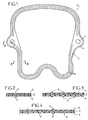
- the seal 2 shown in the drawing is a cylinder head cover gasket thermal motor.
- This joint comprises a core 3 constituted by a strip metal plate in galvanized steel. This strip is coated, on its two faces, of two layers of elastomer 4, such as a silicone.
- the thickness of the core is of the order of 0.2 mm.
- the thickness of each layer of elastomer varies from about 0 to 0.3 mm.
- Gasket shown in the drawing has two holes 5 for the passage of the screws Tightening.
- the thickness of the two layers 4 of elastomer varies around the periphery of the joint, this thickness being minimal in the tightening zones, that is to say at the level of the holes 5, and being maximum in the end zones, that is to say the zones offset by 90 "with respect to the holes 5.
- the thickness of the joint is barely greater than the thickness of the metal strip 3, while in thicker zones offset by 90 °, it can be around from 0.35 to 0.40mm, given the greater thickness of the 4 layers of elastomer.
- each layer of polymer 4 has longitudinal threads 6, of general section triangular, with a variable height of the order of 0.1 to 0.5 mm. These nets 6 are located taking into account the stresses exerted on the joint to ensure optimum sealing. This is how in the hole areas attachment 5, there is only one thread, while on the rest of the length of the joint there are three parallel threads constituting three barriers sealing.
- the two layers 4 of elastomer are deposited on the core 3, operation during which their fixation is obtained on this core thanks adhesion components.
- the assembly is then placed in a heated mold, in which the conformation of the two layers of elastomer then their vulcanization. he is also possible to improve this fixing by a mechanical hooking, using of punctures 7 formed in the core 3, on either side thereof, these punctured carrying out, in addition to the mechanical attachment of the polymer layers, the clamping stop function.
- the invention provides a great improvement to the existing technique by providing a simple structure obtained in a single operation, comprising a core made of an inexpensive material ensuring good mechanical strength at the joint, and two layers of elastomer arranged on either side of the core ensuring, for their part, the sealing function, with the possibility of modulation of the thicknesses of these layers to take account of constraints related to the environment of the joint.
Description
Claims (9)
- Procédé de fabrication d'un joint statique d'étanchéité, caractérisé en ce qu'il comprend les étapes consistant à :déposer à froid sur chacune des faces d'une âme plate métallique (3), réalisée en acier doux, un composant d'adhérence,déposer à froid sur chacune des faces de l'âme (3) une couche d'élastomère (4),placer l'âme plate métallique (3) revêtue d'élastomère, dans un moule chauffé de façon à réaliser la mise en forme de chaque couche d'élastomère, dont l'épaisseur varie en fonction de la forme des pièces entre lesquelles le joint est destiné à être monté, et des impératifs d'étanchéité, et de façon à former sur chaque couche d'élastomère et le long du pourtour du joint, au moins un filet continu ou nervure (6) de section de forme générale triangulaire, de hauteur variant entre 0,05 et 0,5 mm,et à vulcaniser à chaud l'élastomère.
- Procédé de fabrication d'un joint statique selon la revendication 1, caractérisé en ce que l'âme plate métallique (3) recouverte d'élastomère est placée dans un moule de façon à former, en outre, une surépaisseur d'élastomère à proximité de l'un des bords de l'âme plate métallique (3).
- Joint statique d'étanchéité caractérisé en ce qu'il comprend une âme plate métallique (3) réalisée en acier doux, dont chacune des faces est revêtue d'une couche (4) d'élastomère liée par des composants permettant son adhérence sur le métal et dont l'épaisseur varie en fonction de la forme des pièces entre lesquelles le joint est destiné à être monté et des impératifs d'étanchéité en chaque point de la surface du joint, chaque couche d'élastomère (4) comportant, le long du pourtour du joint au moins un filet continu ou nervure (6), de section de forme générale triangulaire, de hauteur variant entre 0,05 et 0,5 mm.
- Joint statique d'étanchéité selon la revendication 3, caractérisé en ce qu'au moins une couche d'élastomère (4) présente, à proximité d'au moins l'un de ses bords, au moins une surépaisseur localisée, afin de réaliser, lors du serrage, une étanchéité latérale.
- Joint statique d'étanchéité selon la revendication 3 ou la revendication 4, caractérisé en ce que l'acier doux constitutif de l'âme (3) est un acier zingué.
- Joint statique d'étanchéité selon l'une des revendications 3 à 5, caractérisé en ce que l'épaisseur de l'âme (3) est de l'ordre de 0,2mm.
- Joint statique d'étanchéité selon l'une des revendications 3 à 6, caractérisé en ce que l'épaisseur de chaque couche d'élastomère est comprise entre 0 et 0,3mm.
- Joint statique d'étanchéité selon l'une des revendications 3 à 7, caractérisé en ce que l'épaisseur de chaque couche d'élastomère varie sur le pourtour du joint, étant minimale dans les zones de serrage, et étant maximale dans les zones éloignées desdites zones de serrage.
- Joint statique d'étanchéité selon l'une des revendications 3 à 8, caractérisé en ce que l'âme métallique (3) présente des crevés (7) formant butée de serrage et améliorant l'accrochage des couches (4) d'élastomère.
Applications Claiming Priority (3)
| Application Number | Priority Date | Filing Date | Title |
|---|---|---|---|
| FR9711420 | 1997-09-09 | ||
| FR9711420A FR2768211B1 (fr) | 1997-09-09 | 1997-09-09 | Joint statique d'etancheite |
| PCT/FR1998/001924 WO1999013248A1 (fr) | 1997-09-09 | 1998-09-09 | Joint statique d'etancheite |
Publications (2)
| Publication Number | Publication Date |
|---|---|
| EP1023549A1 EP1023549A1 (fr) | 2000-08-02 |
| EP1023549B1 true EP1023549B1 (fr) | 2004-05-12 |
Family
ID=9511065
Family Applications (1)
| Application Number | Title | Priority Date | Filing Date |
|---|---|---|---|
| EP98943948A Expired - Lifetime EP1023549B1 (fr) | 1997-09-09 | 1998-09-09 | Joint statique d'etancheite |
Country Status (10)
| Country | Link |
|---|---|
| US (1) | US6530575B2 (fr) |
| EP (1) | EP1023549B1 (fr) |
| AT (1) | ATE266825T1 (fr) |
| BR (1) | BR9814926A (fr) |
| DE (1) | DE69823856T2 (fr) |
| DK (1) | DK1023549T3 (fr) |
| ES (1) | ES2219903T3 (fr) |
| FR (1) | FR2768211B1 (fr) |
| PT (1) | PT1023549E (fr) |
| WO (1) | WO1999013248A1 (fr) |
Cited By (5)
| Publication number | Priority date | Publication date | Assignee | Title |
|---|---|---|---|---|
| WO2007093266A1 (fr) * | 2006-02-16 | 2007-08-23 | Federal-Mogul Sealing Systems Bretten Gmbh | Joint d'étanchéité plat soumis à de fortes sollicitations pour des moteurs à combustion interne |
| WO2009077017A1 (fr) * | 2007-12-19 | 2009-06-25 | Federal-Mogul Sealing Systems Gmbh | Joint d'étanchéité métallique plat et procédé pour sa fabrication |
| DE102009032925B3 (de) * | 2009-07-14 | 2011-01-27 | Elringklinger Ag | Verfahren zum Herstellen einer Dichtkontur auf einer flächig ausgebildeten Funktionslage |
| DE102009032924A1 (de) | 2009-07-14 | 2011-02-03 | Elringklinger Ag | Verfahren zum Formen und Festlegen eines elastomeren, konturierten Dichtmediums auf einem Substrat |
| DE102010030072A1 (de) * | 2010-06-15 | 2011-12-15 | Federal-Mogul Sealing Systems Gmbh | Statistische Dichtung mit integriertem Sieb- oder Filterelement |
Families Citing this family (39)
| Publication number | Priority date | Publication date | Assignee | Title |
|---|---|---|---|---|
| US6889865B1 (en) * | 2000-07-07 | 2005-05-10 | Xerxes Corporation | Method and apparatus for pressure testing storage tanks |
| DE10048871A1 (de) * | 2000-07-14 | 2002-03-14 | Freudenberg Carl | Flachdichtung |
| US7230167B2 (en) | 2001-08-31 | 2007-06-12 | Syngenta Participations Ag | Modified Cry3A toxins and nucleic acid sequences coding therefor |
| TW524187U (en) * | 2001-12-31 | 2003-03-11 | Nailermate Entpr Corp | Structure for mounting urging sheet of nailing gun |
| DE10247559A1 (de) * | 2002-10-11 | 2004-05-13 | Federal-Mogul Sealing Systems Bretten Gmbh & Co. Kg | Dichtelement |
| FR2846067B1 (fr) * | 2002-10-18 | 2005-01-14 | Valeo Vision | Joint d'etancheite pour bloc optique automobile |
| DE10306211A1 (de) * | 2003-02-13 | 2004-08-26 | Mann + Hummel Gmbh | Dichtung zur Abdichtung einer Verbindung zweier Formteile |
| GB0329890D0 (en) * | 2003-12-23 | 2004-01-28 | Airbus Uk Ltd | Method of Sealing a Joint |
| GB0329891D0 (en) * | 2003-12-23 | 2004-01-28 | Airbus Uk Ltd | A sealing material |
| US7004879B2 (en) * | 2004-01-12 | 2006-02-28 | American Axle & Manufacturing, Inc. | Axle differential with stamped carrier cover pan |
| DE102004020446B3 (de) | 2004-04-27 | 2005-11-10 | Federal-Mogul Sealing Systems Gmbh | Zylinderkopfdichtung für Brennkraftmaschinen |
| FR2871210B1 (fr) | 2004-06-07 | 2006-10-06 | Meillor Sa Sa | Joint d'etancheite incorporant un revetement en mousse ou analogue ainsi qu'un limiteur d'ecrasement dudit revetement |
| US20050280214A1 (en) * | 2004-06-22 | 2005-12-22 | Richards Jeffrey L | Elastomer coated screen gasket |
| DE102004034824B4 (de) * | 2004-07-19 | 2006-10-05 | Reinz-Dichtungs-Gmbh | Metallische Flachdichtung |
| FR2873181B1 (fr) | 2004-07-19 | 2007-12-07 | Meillor Sa Sa | Joint d'etancheite comprenant une ame rigide et au moins une barriere d'etancheite en materiau souple |
| FR2873777B1 (fr) | 2004-08-02 | 2008-10-03 | Fed Mogul Sealing Systems Soc | Joint statique d'etancheite |
| DE102004052620A1 (de) * | 2004-10-29 | 2006-06-01 | BSH Bosch und Siemens Hausgeräte GmbH | Modulares Kältegerät |
| US7241246B2 (en) * | 2004-11-18 | 2007-07-10 | American Axle & Manufacturing, Inc. | Differential assembly with cover gasket having integral magnet |
| JP5473192B2 (ja) * | 2006-01-25 | 2014-04-16 | 株式会社豊田自動織機 | 電動コンプレッサ |
| DE102006008270B4 (de) * | 2006-02-22 | 2009-01-08 | Federal-Mogul Sealing Systems Gmbh | Zylinderkopfdichtung mit Kanal |
| US7905498B2 (en) * | 2006-03-28 | 2011-03-15 | Interface Solutions, Inc. | Gasket formed from various material |
| US7806413B2 (en) * | 2006-11-08 | 2010-10-05 | Federal-Mogul Corporation | Static gasket |
| GB0720705D0 (en) | 2007-10-23 | 2007-12-05 | Airbus Uk Ltd | Fastener joint with sealing gasket |
| NZ776389A (en) | 2008-06-05 | 2023-02-24 | ResMed Pty Ltd | Treatment of respiratory conditions |
| US8579299B2 (en) * | 2009-04-03 | 2013-11-12 | Interface Solutions, Inc. | Gasket having adhesive element |
| EP2317150B1 (fr) | 2009-10-29 | 2019-12-18 | ResMed Pty Ltd | Dispositif de ventilation de patient et composants associés |
| CN103201543B (zh) * | 2011-06-09 | 2015-09-09 | Nok株式会社 | 密封垫及其制造方法 |
| JP5723846B2 (ja) * | 2012-10-04 | 2015-05-27 | 内山工業株式会社 | ガスケット |
| DE102012219808A1 (de) * | 2012-10-30 | 2014-04-30 | Federal-Mogul Sealing Systems Gmbh | Metall-Elastomerdichtung mit integrierter Schmutz- und Medienabdichtung |
| CN103267121B (zh) * | 2013-05-14 | 2015-09-30 | 宁波信幸隆密封制品有限公司 | 一种全周封垫片及其生产工艺 |
| USD778142S1 (en) | 2015-03-11 | 2017-02-07 | Garlock Sealing Technologies, Llc | Gasket having raised sealing surface pattern |
| USD753274S1 (en) | 2015-03-11 | 2016-04-05 | Garlock Sealing Technologies, Llc | Gasket having raised sealing surface pattern |
| USD758728S1 (en) | 2015-03-11 | 2016-06-14 | Garlock Sealing Technologies, Llc | Gasket having raised sealing surface pattern |
| USD777016S1 (en) | 2015-03-11 | 2017-01-24 | Garlock Sealing Technologies, Llc | Gasket having raised sealing surface pattern |
| USD759217S1 (en) | 2015-03-11 | 2016-06-14 | Garlock Sealing Technologies, Llc | Gasket having raised sealing surface pattern |
| USD753275S1 (en) | 2015-03-11 | 2016-04-05 | Garlock Sealing Technologies, Llc | Gasket having raised sealing surface pattern |
| USD759218S1 (en) | 2015-03-11 | 2016-06-14 | Garlock Sealing Technologies, Llc | Gasket having raised sealing surface pattern |
| USD759219S1 (en) | 2015-03-11 | 2016-06-14 | Garlock Sealing Technologies, Llc | Gasket having raised sealing surface pattern |
| CN108150303B (zh) * | 2017-12-25 | 2020-10-16 | 重庆长安汽车股份有限公司 | 一种发动机气缸盖罩密封垫 |
Family Cites Families (24)
| Publication number | Priority date | Publication date | Assignee | Title |
|---|---|---|---|---|
| US3352564A (en) * | 1965-04-09 | 1967-11-14 | Gen Motors Corp | Gasket construction |
| US3837657A (en) * | 1971-12-22 | 1974-09-24 | Farnam F Co | Beaded gasket and method of using same |
| US3794333A (en) * | 1972-07-20 | 1974-02-26 | Felt Products Mfg Co | Gasket |
| US3930656A (en) * | 1974-02-22 | 1976-01-06 | Parker-Hannifin Corporation | Sealed joint and gasket therefor |
| US4535999A (en) * | 1984-07-23 | 1985-08-20 | Felt Products Mfg. Co. | Gasket assembly having a sealing member suspended in a clear-through opening and method of making same |
| US4535996A (en) * | 1985-01-18 | 1985-08-20 | Felt Products Mfg. Co. | Gasket assembly for oil pans and the like and method of making same |
| US4625979A (en) * | 1985-08-05 | 1986-12-02 | Felt Products Mfg. Co. | Seal assembly having a low extrusion resistant elastomeric sealing bead |
| JPS62155375A (ja) * | 1985-12-27 | 1987-07-10 | Nippon Metal Gasket Kk | 金属ガスケツト |
| JPH0414681Y2 (fr) * | 1986-04-11 | 1992-04-02 | ||
| DE3631052A1 (de) * | 1986-09-12 | 1988-03-24 | Klinger Ag | Flachdichtung |
| GB8701804D0 (en) * | 1987-01-28 | 1987-03-04 | Dow Corning | Gaskets |
| DE68924832T2 (de) * | 1988-05-27 | 1996-04-18 | Toshimitsu Terai | Metallischer dichtungsring. |
| US5130203A (en) * | 1988-07-28 | 1992-07-14 | Nippon Leakless Industry Co., Ltd. | Metal gasket and method of producing the same |
| US4911972A (en) * | 1988-08-12 | 1990-03-27 | Union Carbide Corporation | Insulating composite gasket |
| US4852893A (en) * | 1988-12-06 | 1989-08-01 | Fel-Pro Incorporated | Elastomeric coated perforated metal core composite gasket and method of making same |
| US5164136A (en) * | 1989-09-08 | 1992-11-17 | Norton Company | Method for forming flexible gaskets |
| US4955621A (en) * | 1989-09-22 | 1990-09-11 | Jpi Transportation Products, Inc. | Gasket |
| DE4109951C2 (de) * | 1991-03-26 | 1993-12-23 | Reinz Dichtungs Gmbh | Blech-Elastomer-Flachdichtung |
| US5267740A (en) * | 1992-02-20 | 1993-12-07 | Fel-Pro Incorporated | Metal head gasket with integrated sealing aids |
| DE4402399C1 (de) * | 1994-01-27 | 1996-01-25 | Payen Goetze Gmbh | Flachdichtung, insbesondere metallische Zylinderkopfdichtung |
| GB2290586B (en) * | 1994-06-15 | 1997-08-13 | T & N Technology Ltd | Beads for gaskets |
| FR2724439B1 (fr) * | 1994-09-13 | 1996-10-25 | Curty Payen Sa | Joint metal-elastomere, notamment joint d'etancheite plat |
| US5615898A (en) * | 1995-08-15 | 1997-04-01 | Clark; James M. | Bead seal motorcycle gasket |
| JP3455385B2 (ja) * | 1996-12-27 | 2003-10-14 | 石川ガスケット株式会社 | ガスケット |
-
1997
- 1997-09-09 FR FR9711420A patent/FR2768211B1/fr not_active Expired - Fee Related
-
1998
- 1998-09-09 BR BR9814926-1A patent/BR9814926A/pt not_active IP Right Cessation
- 1998-09-09 US US09/486,835 patent/US6530575B2/en not_active Expired - Lifetime
- 1998-09-09 PT PT98943948T patent/PT1023549E/pt unknown
- 1998-09-09 DK DK98943948T patent/DK1023549T3/da active
- 1998-09-09 DE DE69823856T patent/DE69823856T2/de not_active Expired - Lifetime
- 1998-09-09 AT AT98943948T patent/ATE266825T1/de not_active IP Right Cessation
- 1998-09-09 ES ES98943948T patent/ES2219903T3/es not_active Expired - Lifetime
- 1998-09-09 WO PCT/FR1998/001924 patent/WO1999013248A1/fr active IP Right Grant
- 1998-09-09 EP EP98943948A patent/EP1023549B1/fr not_active Expired - Lifetime
Cited By (7)
| Publication number | Priority date | Publication date | Assignee | Title |
|---|---|---|---|---|
| WO2007093266A1 (fr) * | 2006-02-16 | 2007-08-23 | Federal-Mogul Sealing Systems Bretten Gmbh | Joint d'étanchéité plat soumis à de fortes sollicitations pour des moteurs à combustion interne |
| WO2009077017A1 (fr) * | 2007-12-19 | 2009-06-25 | Federal-Mogul Sealing Systems Gmbh | Joint d'étanchéité métallique plat et procédé pour sa fabrication |
| DE102007061084A1 (de) * | 2007-12-19 | 2009-07-02 | Federal-Mogul Sealing Systems Gmbh | Metallische Flachdichtung und Herstellverfahren |
| DE102009032925B3 (de) * | 2009-07-14 | 2011-01-27 | Elringklinger Ag | Verfahren zum Herstellen einer Dichtkontur auf einer flächig ausgebildeten Funktionslage |
| DE102009032924A1 (de) | 2009-07-14 | 2011-02-03 | Elringklinger Ag | Verfahren zum Formen und Festlegen eines elastomeren, konturierten Dichtmediums auf einem Substrat |
| DE102009032925C5 (de) | 2009-07-14 | 2018-12-13 | Elringklinger Ag | Verfahren zum Herstellen einer Dichtkontur auf einer flächig ausgebildeten Funktionslage |
| DE102010030072A1 (de) * | 2010-06-15 | 2011-12-15 | Federal-Mogul Sealing Systems Gmbh | Statistische Dichtung mit integriertem Sieb- oder Filterelement |
Also Published As
| Publication number | Publication date |
|---|---|
| FR2768211A1 (fr) | 1999-03-12 |
| DE69823856T2 (de) | 2005-04-28 |
| US6530575B2 (en) | 2003-03-11 |
| PT1023549E (pt) | 2004-08-31 |
| ATE266825T1 (de) | 2004-05-15 |
| ES2219903T3 (es) | 2004-12-01 |
| EP1023549A1 (fr) | 2000-08-02 |
| BR9814926A (pt) | 2000-09-05 |
| DK1023549T3 (da) | 2004-08-09 |
| FR2768211B1 (fr) | 1999-10-22 |
| DE69823856D1 (de) | 2004-06-17 |
| US20020163139A1 (en) | 2002-11-07 |
| WO1999013248A1 (fr) | 1999-03-18 |
Similar Documents
| Publication | Publication Date | Title |
|---|---|---|
| EP1023549B1 (fr) | Joint statique d'etancheite | |
| EP0041906B1 (fr) | Joint de culasse pour moteur à combustion interne | |
| EP0702174B1 (fr) | Joint d'étanchéité plat métal-élastomère | |
| EP1779006A2 (fr) | Joint statique d'etancheite | |
| FR2543247A1 (fr) | Joint composite | |
| CA2118945A1 (fr) | Joint plat, notamment pour moteur a combustion interne, et procede de fabrication associe | |
| EP0148652A1 (fr) | Perfectionnements apportés aux moyens d'isolation thermique de tuyauteries soumises à des contraintes thermiques, hydrostatiques et mécaniques et à leur mise en place, et procédé de réalisation desdits moyens d'isolation | |
| FR2521638A1 (fr) | Joint de culasse pour moteur a combustion interne | |
| FR2725259A1 (fr) | Bague d'etancheite activee par pression | |
| FR2631412A1 (fr) | Joint d'etancheite feuillete en acier a bourrelets distincts | |
| EP0119906A1 (fr) | Garniture pour montage d'un vitrage de sécurité dans une baie notamment d'un pare-brise pour véhicule automobile | |
| FR2526912A1 (fr) | Joint metallique d'etancheite, notamment pour moteurs | |
| FR2512912A1 (fr) | Joint a caracteristiques d'etancheite ameliorees et procede de fabrication de ce joint | |
| FR2636397A1 (fr) | Joint d'etancheite en acier lamine avec une large surface d'etancheite | |
| EP0028576B1 (fr) | Joint de culasse pour moteur à combustion interne | |
| EP0095989B1 (fr) | Système d'étanchéité aux fluides pour joint de culasse de moteur à combustion interne | |
| EP0500483A1 (fr) | Dispositif d'étanchéité entre au moins deux éléments parallèles non jointifs | |
| FR2566871A1 (fr) | Joint d'etancheite pour vanne a obturateur rotatif et son procede de fabrication | |
| EP0394117B1 (fr) | Revêtement stratifié, élément thermiquement isolant pourvu d'un tel revêtement | |
| FR2737255A1 (fr) | Joint de culasse pour moteur a combustion interne | |
| WO1998034061A1 (fr) | Enveloppe d'isolation thermique, notamment pour la construction de canalisations sous-marines vehiculant des produits petroliers | |
| FR2489463A1 (fr) | Joint annulaire d'etancheite, procede de construction de ce joint, moules et dispositif pour la mise en oeuvre de ce procede, application de ce joint pour la connexion de deux gaines | |
| FR2509414A1 (fr) | Joint plat perfectionne et procede de fabrication de ce joint | |
| FR2512155A1 (fr) | Joint d'etancheite plat et son procede de fabrication | |
| FR2687732A1 (fr) | Joint de culasse et procede de fabrication. |
Legal Events
| Date | Code | Title | Description |
|---|---|---|---|
| PUAI | Public reference made under article 153(3) epc to a published international application that has entered the european phase |
Free format text: ORIGINAL CODE: 0009012 |
|
| 17P | Request for examination filed |
Effective date: 20000328 |
|
| AK | Designated contracting states |
Kind code of ref document: A1 Designated state(s): AT BE CH DE DK ES FR GB IT LI NL PT SE |
|
| 17Q | First examination report despatched |
Effective date: 20020212 |
|
| GRAP | Despatch of communication of intention to grant a patent |
Free format text: ORIGINAL CODE: EPIDOSNIGR1 |
|
| GRAS | Grant fee paid |
Free format text: ORIGINAL CODE: EPIDOSNIGR3 |
|
| GRAA | (expected) grant |
Free format text: ORIGINAL CODE: 0009210 |
|
| AK | Designated contracting states |
Kind code of ref document: B1 Designated state(s): AT BE CH DE DK ES FR GB IT LI NL PT SE |
|
| REG | Reference to a national code |
Ref country code: GB Ref legal event code: FG4D Free format text: NOT ENGLISH |
|
| REG | Reference to a national code |
Ref country code: CH Ref legal event code: NV Representative=s name: MICHELI & CIE INGENIEURS-CONSEILS Ref country code: CH Ref legal event code: EP |
|
| GBT | Gb: translation of ep patent filed (gb section 77(6)(a)/1977) |
Effective date: 20040512 |
|
| REF | Corresponds to: |
Ref document number: 69823856 Country of ref document: DE Date of ref document: 20040617 Kind code of ref document: P |
|
| REG | Reference to a national code |
Ref country code: DK Ref legal event code: T3 |
|
| REG | Reference to a national code |
Ref country code: SE Ref legal event code: TRGR |
|
| REG | Reference to a national code |
Ref country code: PT Ref legal event code: SC4A Free format text: AVAILABILITY OF NATIONAL TRANSLATION Effective date: 20040616 |
|
| REG | Reference to a national code |
Ref country code: ES Ref legal event code: FG2A Ref document number: 2219903 Country of ref document: ES Kind code of ref document: T3 |
|
| PLAQ | Examination of admissibility of opposition: information related to despatch of communication + time limit deleted |
Free format text: ORIGINAL CODE: EPIDOSDOPE2 |
|
| PLAR | Examination of admissibility of opposition: information related to receipt of reply deleted |
Free format text: ORIGINAL CODE: EPIDOSDOPE4 |
|
| PLBQ | Unpublished change to opponent data |
Free format text: ORIGINAL CODE: EPIDOS OPPO |
|
| PLBI | Opposition filed |
Free format text: ORIGINAL CODE: 0009260 |
|
| PLAX | Notice of opposition and request to file observation + time limit sent |
Free format text: ORIGINAL CODE: EPIDOSNOBS2 |
|
| 26 | Opposition filed |
Opponent name: ELRINGKLINGER AG Effective date: 20050210 Opponent name: CARL FREUDENBERG KG Effective date: 20050209 |
|
| NLR1 | Nl: opposition has been filed with the epo |
Opponent name: ELRINGKLINGER AG Opponent name: CARL FREUDENBERG KG |
|
| PLBB | Reply of patent proprietor to notice(s) of opposition received |
Free format text: ORIGINAL CODE: EPIDOSNOBS3 |
|
| PLAY | Examination report in opposition despatched + time limit |
Free format text: ORIGINAL CODE: EPIDOSNORE2 |
|
| PLAH | Information related to despatch of examination report in opposition + time limit modified |
Free format text: ORIGINAL CODE: EPIDOSCORE2 |
|
| PLBC | Reply to examination report in opposition received |
Free format text: ORIGINAL CODE: EPIDOSNORE3 |
|
| PGFP | Annual fee paid to national office [announced via postgrant information from national office to epo] |
Ref country code: DK Payment date: 20090811 Year of fee payment: 12 |
|
| PGFP | Annual fee paid to national office [announced via postgrant information from national office to epo] |
Ref country code: NL Payment date: 20090915 Year of fee payment: 12 Ref country code: CH Payment date: 20090811 Year of fee payment: 12 Ref country code: AT Payment date: 20090807 Year of fee payment: 12 |
|
| PLCK | Communication despatched that opposition was rejected |
Free format text: ORIGINAL CODE: EPIDOSNREJ1 |
|
| APBM | Appeal reference recorded |
Free format text: ORIGINAL CODE: EPIDOSNREFNO |
|
| APBP | Date of receipt of notice of appeal recorded |
Free format text: ORIGINAL CODE: EPIDOSNNOA2O |
|
| APAH | Appeal reference modified |
Free format text: ORIGINAL CODE: EPIDOSCREFNO |
|
| PGFP | Annual fee paid to national office [announced via postgrant information from national office to epo] |
Ref country code: BE Payment date: 20091022 Year of fee payment: 12 |
|
| APBQ | Date of receipt of statement of grounds of appeal recorded |
Free format text: ORIGINAL CODE: EPIDOSNNOA3O |
|
| PLAB | Opposition data, opponent's data or that of the opponent's representative modified |
Free format text: ORIGINAL CODE: 0009299OPPO |
|
| R26 | Opposition filed (corrected) |
Opponent name: ELRINGKLINGER AG Effective date: 20050210 Opponent name: CARL FREUDENBERG KG Effective date: 20050209 |
|
| BERE | Be: lapsed |
Owner name: *FEDERAL MOGUL SEALING SYSTEMS Effective date: 20100930 |
|
| REG | Reference to a national code |
Ref country code: NL Ref legal event code: V1 Effective date: 20110401 |
|
| REG | Reference to a national code |
Ref country code: CH Ref legal event code: PL |
|
| REG | Reference to a national code |
Ref country code: DK Ref legal event code: EBP |
|
| PG25 | Lapsed in a contracting state [announced via postgrant information from national office to epo] |
Ref country code: LI Free format text: LAPSE BECAUSE OF NON-PAYMENT OF DUE FEES Effective date: 20100930 Ref country code: BE Free format text: LAPSE BECAUSE OF NON-PAYMENT OF DUE FEES Effective date: 20100930 Ref country code: CH Free format text: LAPSE BECAUSE OF NON-PAYMENT OF DUE FEES Effective date: 20100930 |
|
| PG25 | Lapsed in a contracting state [announced via postgrant information from national office to epo] |
Ref country code: AT Free format text: LAPSE BECAUSE OF NON-PAYMENT OF DUE FEES Effective date: 20100909 Ref country code: NL Free format text: LAPSE BECAUSE OF NON-PAYMENT OF DUE FEES Effective date: 20110401 |
|
| PG25 | Lapsed in a contracting state [announced via postgrant information from national office to epo] |
Ref country code: DK Free format text: LAPSE BECAUSE OF NON-PAYMENT OF DUE FEES Effective date: 20100930 |
|
| APBU | Appeal procedure closed |
Free format text: ORIGINAL CODE: EPIDOSNNOA9O |
|
| PLBN | Opposition rejected |
Free format text: ORIGINAL CODE: 0009273 |
|
| STAA | Information on the status of an ep patent application or granted ep patent |
Free format text: STATUS: OPPOSITION REJECTED |
|
| 27O | Opposition rejected |
Effective date: 20130606 |
|
| REG | Reference to a national code |
Ref country code: DE Ref legal event code: R100 Ref document number: 69823856 Country of ref document: DE Effective date: 20130606 |
|
| REG | Reference to a national code |
Ref country code: FR Ref legal event code: PLFP Year of fee payment: 19 |
|
| PGFP | Annual fee paid to national office [announced via postgrant information from national office to epo] |
Ref country code: IT Payment date: 20160914 Year of fee payment: 19 Ref country code: GB Payment date: 20160830 Year of fee payment: 19 |
|
| PGFP | Annual fee paid to national office [announced via postgrant information from national office to epo] |
Ref country code: FR Payment date: 20160817 Year of fee payment: 19 Ref country code: SE Payment date: 20160908 Year of fee payment: 19 Ref country code: PT Payment date: 20160826 Year of fee payment: 19 |
|
| PGFP | Annual fee paid to national office [announced via postgrant information from national office to epo] |
Ref country code: ES Payment date: 20160907 Year of fee payment: 19 |
|
| PGFP | Annual fee paid to national office [announced via postgrant information from national office to epo] |
Ref country code: DE Payment date: 20160928 Year of fee payment: 19 |
|
| REG | Reference to a national code |
Ref country code: DE Ref legal event code: R119 Ref document number: 69823856 Country of ref document: DE |
|
| REG | Reference to a national code |
Ref country code: SE Ref legal event code: EUG |
|
| GBPC | Gb: european patent ceased through non-payment of renewal fee |
Effective date: 20170909 |
|
| PG25 | Lapsed in a contracting state [announced via postgrant information from national office to epo] |
Ref country code: PT Free format text: LAPSE BECAUSE OF NON-PAYMENT OF DUE FEES Effective date: 20180309 |
|
| REG | Reference to a national code |
Ref country code: FR Ref legal event code: ST Effective date: 20180531 |
|
| PG25 | Lapsed in a contracting state [announced via postgrant information from national office to epo] |
Ref country code: DE Free format text: LAPSE BECAUSE OF NON-PAYMENT OF DUE FEES Effective date: 20180404 Ref country code: GB Free format text: LAPSE BECAUSE OF NON-PAYMENT OF DUE FEES Effective date: 20170909 |
|
| PG25 | Lapsed in a contracting state [announced via postgrant information from national office to epo] |
Ref country code: IT Free format text: LAPSE BECAUSE OF NON-PAYMENT OF DUE FEES Effective date: 20170909 Ref country code: FR Free format text: LAPSE BECAUSE OF NON-PAYMENT OF DUE FEES Effective date: 20171002 |
|
| REG | Reference to a national code |
Ref country code: ES Ref legal event code: FD2A Effective date: 20181019 |
|
| PG25 | Lapsed in a contracting state [announced via postgrant information from national office to epo] |
Ref country code: PT Free format text: LAPSE BECAUSE OF EXPIRATION OF PROTECTION Effective date: 20181003 |
|
| PG25 | Lapsed in a contracting state [announced via postgrant information from national office to epo] |
Ref country code: ES Free format text: LAPSE BECAUSE OF NON-PAYMENT OF DUE FEES Effective date: 20170910 |
|
| PG25 | Lapsed in a contracting state [announced via postgrant information from national office to epo] |
Ref country code: SE Free format text: LAPSE BECAUSE OF NON-PAYMENT OF DUE FEES Effective date: 20170910 |