EP1022187A2 - Vehicle light - Google Patents
Vehicle light Download PDFInfo
- Publication number
- EP1022187A2 EP1022187A2 EP00100583A EP00100583A EP1022187A2 EP 1022187 A2 EP1022187 A2 EP 1022187A2 EP 00100583 A EP00100583 A EP 00100583A EP 00100583 A EP00100583 A EP 00100583A EP 1022187 A2 EP1022187 A2 EP 1022187A2
- Authority
- EP
- European Patent Office
- Prior art keywords
- light
- light exit
- vehicle lamp
- main surface
- longitudinal direction
- Prior art date
- Legal status (The legal status is an assumption and is not a legal conclusion. Google has not performed a legal analysis and makes no representation as to the accuracy of the status listed.)
- Granted
Links
Images

Classifications
-
- B—PERFORMING OPERATIONS; TRANSPORTING
- B60—VEHICLES IN GENERAL
- B60Q—ARRANGEMENT OF SIGNALLING OR LIGHTING DEVICES, THE MOUNTING OR SUPPORTING THEREOF OR CIRCUITS THEREFOR, FOR VEHICLES IN GENERAL
- B60Q1/00—Arrangement of optical signalling or lighting devices, the mounting or supporting thereof or circuits therefor
- B60Q1/26—Arrangement of optical signalling or lighting devices, the mounting or supporting thereof or circuits therefor the devices being primarily intended to indicate the vehicle, or parts thereof, or to give signals, to other traffic
- B60Q1/2661—Arrangement of optical signalling or lighting devices, the mounting or supporting thereof or circuits therefor the devices being primarily intended to indicate the vehicle, or parts thereof, or to give signals, to other traffic mounted on parts having other functions
- B60Q1/2665—Arrangement of optical signalling or lighting devices, the mounting or supporting thereof or circuits therefor the devices being primarily intended to indicate the vehicle, or parts thereof, or to give signals, to other traffic mounted on parts having other functions on rear-view mirrors
-
- B—PERFORMING OPERATIONS; TRANSPORTING
- B60—VEHICLES IN GENERAL
- B60Q—ARRANGEMENT OF SIGNALLING OR LIGHTING DEVICES, THE MOUNTING OR SUPPORTING THEREOF OR CIRCUITS THEREFOR, FOR VEHICLES IN GENERAL
- B60Q1/00—Arrangement of optical signalling or lighting devices, the mounting or supporting thereof or circuits therefor
- B60Q1/26—Arrangement of optical signalling or lighting devices, the mounting or supporting thereof or circuits therefor the devices being primarily intended to indicate the vehicle, or parts thereof, or to give signals, to other traffic
- B60Q1/2696—Mounting of devices using LEDs
-
- F—MECHANICAL ENGINEERING; LIGHTING; HEATING; WEAPONS; BLASTING
- F21—LIGHTING
- F21S—NON-PORTABLE LIGHTING DEVICES; SYSTEMS THEREOF; VEHICLE LIGHTING DEVICES SPECIALLY ADAPTED FOR VEHICLE EXTERIORS
- F21S43/00—Signalling devices specially adapted for vehicle exteriors, e.g. brake lamps, direction indicator lights or reversing lights
- F21S43/10—Signalling devices specially adapted for vehicle exteriors, e.g. brake lamps, direction indicator lights or reversing lights characterised by the light source
- F21S43/13—Signalling devices specially adapted for vehicle exteriors, e.g. brake lamps, direction indicator lights or reversing lights characterised by the light source characterised by the type of light source
- F21S43/14—Light emitting diodes [LED]
-
- F—MECHANICAL ENGINEERING; LIGHTING; HEATING; WEAPONS; BLASTING
- F21—LIGHTING
- F21S—NON-PORTABLE LIGHTING DEVICES; SYSTEMS THEREOF; VEHICLE LIGHTING DEVICES SPECIALLY ADAPTED FOR VEHICLE EXTERIORS
- F21S43/00—Signalling devices specially adapted for vehicle exteriors, e.g. brake lamps, direction indicator lights or reversing lights
- F21S43/20—Signalling devices specially adapted for vehicle exteriors, e.g. brake lamps, direction indicator lights or reversing lights characterised by refractors, transparent cover plates, light guides or filters
- F21S43/235—Light guides
- F21S43/236—Light guides characterised by the shape of the light guide
- F21S43/237—Light guides characterised by the shape of the light guide rod-shaped
-
- F—MECHANICAL ENGINEERING; LIGHTING; HEATING; WEAPONS; BLASTING
- F21—LIGHTING
- F21S—NON-PORTABLE LIGHTING DEVICES; SYSTEMS THEREOF; VEHICLE LIGHTING DEVICES SPECIALLY ADAPTED FOR VEHICLE EXTERIORS
- F21S43/00—Signalling devices specially adapted for vehicle exteriors, e.g. brake lamps, direction indicator lights or reversing lights
- F21S43/20—Signalling devices specially adapted for vehicle exteriors, e.g. brake lamps, direction indicator lights or reversing lights characterised by refractors, transparent cover plates, light guides or filters
- F21S43/235—Light guides
- F21S43/242—Light guides characterised by the emission area
- F21S43/243—Light guides characterised by the emission area emitting light from one or more of its extremities
-
- F—MECHANICAL ENGINEERING; LIGHTING; HEATING; WEAPONS; BLASTING
- F21—LIGHTING
- F21S—NON-PORTABLE LIGHTING DEVICES; SYSTEMS THEREOF; VEHICLE LIGHTING DEVICES SPECIALLY ADAPTED FOR VEHICLE EXTERIORS
- F21S43/00—Signalling devices specially adapted for vehicle exteriors, e.g. brake lamps, direction indicator lights or reversing lights
- F21S43/20—Signalling devices specially adapted for vehicle exteriors, e.g. brake lamps, direction indicator lights or reversing lights characterised by refractors, transparent cover plates, light guides or filters
- F21S43/235—Light guides
- F21S43/242—Light guides characterised by the emission area
- F21S43/245—Light guides characterised by the emission area emitting light from one or more of its major surfaces
-
- F—MECHANICAL ENGINEERING; LIGHTING; HEATING; WEAPONS; BLASTING
- F21—LIGHTING
- F21S—NON-PORTABLE LIGHTING DEVICES; SYSTEMS THEREOF; VEHICLE LIGHTING DEVICES SPECIALLY ADAPTED FOR VEHICLE EXTERIORS
- F21S43/00—Signalling devices specially adapted for vehicle exteriors, e.g. brake lamps, direction indicator lights or reversing lights
- F21S43/20—Signalling devices specially adapted for vehicle exteriors, e.g. brake lamps, direction indicator lights or reversing lights characterised by refractors, transparent cover plates, light guides or filters
- F21S43/235—Light guides
- F21S43/247—Light guides with a single light source being coupled into the light guide
Definitions
- the invention relates to a vehicle lamp in the preamble of claim 1 Art.
- This light exit disc is a flat body made of a translucent material, which is a installed condition of the main surface outside, one opposite this main inner surface and side edge areas comprising the two Connect main areas together.
- the main surfaces of the light exit disc can principally curved in two mutually perpendicular directions be and have any shape within wide limits in their top view.
- a special embodiment of such a vehicle lamp is, for example known from EP 0 858 932 A2. It is a flashing light, which in the housing of an exterior rearview mirror is installed so that the exterior Main surface of the light exit disc approximately the outer surface of the housing continues continuously. Because in such an application situation behind the light exit pane there is so little space that it is not possible to find one there Arrange light source and surround it with a reflector so that it is from her emitted light through the entire surface of the light exit disc in is emitted approximately uniformly, the light guide arrangement described at the beginning can be used in an advantageous manner.
- the light exit disc has an elongated shape, and the one defined above The longitudinal direction essentially coincides with that when installed horizontally extending longitudinal direction of the light exit disc together.
- the invention has for its object a vehicle lamp of the type mentioned in such a way that even in a transverse direction strongly curved light exit lens geometry good visibility is retained without the number of light emitting diodes having to be increased and / or less light-emitting diodes must be used.
- the invention provides that summarized in claim 1 Characteristics before.
- the inner main surface of the light exit disc is provided with an optical structure that through the outer
- the main surface bundles emerging light in a preferred direction without magnification of space and manufacturing costs one in the desired Preferred direction significantly increased luminous efficiency, so that the number and / or strength of the light sources used can be reduced.
- the light exit disc in all directions much stronger than before be curved so that they conform to the shape or outer contour of any vehicle parts can be adjusted.
- the design options are thus set significantly fewer limits than is the case with the prior art.
- the vehicle lamp is a Side flashing light, particularly in the housing of a motor vehicle exterior mirror can be installed.
- the optically effective structure on the inner The main surface of the light exit disk is designed so that essentially horizontally extending longitudinal direction of light in the vertical direction is bundled so that it emerges essentially in the horizontal direction.
- the optically provided on the inner main surface of the light exit disc effective structure is preferably of a series of strip-shaped, each one of the areas assigned to the light sources is formed in the transverse direction are arranged side by side and parallel to each other in the longitudinal direction extend; each of these areas is against him directly opposite area of the outer major surface in a non-parallel manner arranged tilted.
- a particular advantage of this arrangement is that the amount of light that to the front edge opposite the coupling side and there can emerge clearly through the optically effective structure according to the invention is enlarged.
- An additional decoupling surface is provided on the side of the light exit disk extends substantially in the vertical direction in the assembled state and is tilted towards the vehicle. This will make a significant improvement the visibility of the side turn signal from the direction of travel achieved diagonally behind.
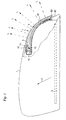
- Fig. 1 the housing 1 of a vehicle exterior mirror is in a schematic manner seen from above as shown in the assembled state of the left vehicle, not shown, extends to the right starting.
- FIG. 1 In the area of the lower housing side in FIG. 1 there is an interior of the housing 1 adjustable mirror 3 arranged schematically by dash-dotted lines is indicated.
- the arrow F indicates the forward direction of travel of the vehicle again.
- a recess 5 of the housing 1 is a constructed according to the invention Side flashing light 7 used, of which only for understanding the invention relevant components are shown.
- this short end face 12 of the light exit disc 9 is a in the longitudinal direction this short end face 12 extending recess 18 incorporated into which protrude the light emitting housing parts of the LEDs 15. Consequently this recess 18 serves as a coupling point through which the light-emitting diodes 15 emitted light into the light exit disk 9 serving as a light guide entry. Part of this light follows the curved path of the light exit disc 9 to the short end face opposite the coupling side 20, at which he exits again.
- the one covered by the light exit disc 9 Arc corresponds approximately to an angle of 90 °, so that of the light emitting diodes 15 essentially transversely to the direction of travel F emitted light on the Front 20 essentially seen in the direction of travel emerges obliquely to the rear.
- the end face 20 preferably has a coupling-out surface 22 which is located in the assembled state extends in the vertical direction and in the section of FIGS. 1 and 2 with the horizontal tangent that in the region of the short end face 20 to the Curvature of the light exit disc 9 can be created, a different from 90 ° Includes angle, i.e. is tilted towards the vehicle. It says this decoupling surface 22 slightly over the outer contour of the mirror housing in front. In this way it is achieved that a light emission in an angular range ⁇ is possible, starting from the opposite direction of travel F (Fig. 1)
- Direction X (FIG. 2) can have a value of 5 ° to 20 °.
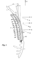
- the inner plane runs in the planes parallel to the sectional plane of FIGS. 1 and 2 Main surface 24 of the light exit disc 9 with a curvature which is approximately the Curvature of the outer main surface 10 corresponds.
- the inside 24 of the light exit disk 9 is provided with an optically effective structure, which consists of a plurality of strip-shaped regions 26 corresponding to the number of light-emitting diodes, which extend parallel to one another in the longitudinal direction of the light exit disk 9 and in the plane of FIG. 3 straight or only slightly curved and arranged so that their direction in this plane, which is to be replaced in the curved regions 26 by the direction of the tangent to this curvature, against the direction Z by an angle ⁇ is inclined, which is greater than the angle ⁇ 1 , which includes the tangent with the direction Z applied to the corresponding region of the outer main surface 10.
- the difference between the angles ⁇ and the respective angle ⁇ 1 depends on the curvature of the opposite region of the outer main surface 10 in the respective sectional plane, and is preferably greater, the greater this curvature.
- the strip-shaped areas 26 can be separated by webs 28 be separated from each other, which are parallel to each other in the longitudinal direction of the Extend light exit disc 9.
- each of the areas 26 can be closed have vertical corrugation in its longitudinal direction in order to achieve a more uniform Scattering of the reflected towards the outer main surface 10 and emerging through this To achieve light.
- the stripes are Areas 26 inclined so that they emit light, otherwise to an excessive degree would emerge downwards, bundle to the horizontal H, as for side indicators is desirable
- the inclination difference ⁇ - ⁇ 1 of the strip-shaped areas can also be selected so that there is increased light radiation in the direction of the arrow Z, if desired, the direction of this arrow Z then also depending on the installation position of the vehicle lamp in question other than that which can be perpendicular upwards.
Abstract
Description
Die Erfindung betrifft eine Fahrzeugleuchte der im Oberbegriff des Anspruches 1
genannten Art.The invention relates to a vehicle lamp in the preamble of
Ein wesentlicher Teil ist dabei die Lichtaustrittsscheibe, die durch die vorliegende Erfindung weitergebildet werden soll. Bei dieser Lichtaustrittsscheibe handelt es sich um einen flachen Körper aus einem lichtdurchlässigen Material, der eine im eingebauten Zustand außen liegende Hauptfläche, eine dieser gegenüber liegende innere Hauptfläche und Seitenkantenbereiche umfaßt, welche die beiden Hauptflächen miteinander verbinden. Dabei können die Hauptflächen der Lichtaustrittsscheibe prinzipiell in zwei zueinander senkrechten Richtungen gekrümmt sein und in ihrer Draufsicht eine innerhalb weiter Grenzen beliebige Form besitzen. Es wird jedoch davon ausgegangen, daß immer zwei einander gegenüber liegende Seitenkantenbereiche vorhanden sind, von denen der eine zum Einkoppeln des von der wenigstens einen Lichtquelle emittierten Lichtes in die als Lichtleiter wirkende Lichtaustrittsscheibe dient, die einen Teil dieses Lichts durch Totalreflexion zum gegenüberliegenden Seitenkantenbereich leitet und dort in einen durch geeignete Wahl der Ausrichtung dieses Seitenkantenbereichs definierbaren Raumwinkel abstrahlt, während der von ihr nicht absorbierte Rest des eingekoppelten Lichts durch die äußere Hauptfläche austritt. Die Richtung, welche die beiden eben erwähnten Seitenkantenbereiche der Lichtaustrittsscheibe miteinander verbindet wird in der vorliegenden Beschreibung als Längsleitrichtung der Lichtaustrittsscheibe bezeichnet.An essential part is the light exit disc, which is provided by the present Invention to be further developed. This light exit disc is is a flat body made of a translucent material, which is a installed condition of the main surface outside, one opposite this main inner surface and side edge areas comprising the two Connect main areas together. The main surfaces of the light exit disc can principally curved in two mutually perpendicular directions be and have any shape within wide limits in their top view. However, it is assumed that there are always two facing each other horizontal side edge areas are available, one of which is for coupling of the light emitted by the at least one light source into the as Light guide acting light exit disc is used that a part of this light through Total reflection leads to the opposite side edge area and there into one definable by suitable choice of the orientation of this side edge area Solid angle emits while the rest of the coupled light emerges through the outer main surface. The direction which the two side edge regions of the light exit pane just mentioned is connected to each other in the present description as a longitudinal direction the light exit disc.
Eine spezielle Ausführungsform einer solchen Fahrzeugleuchte ist beispielsweise aus EP 0 858 932 A2 bekannt. Dabei handelt es sich um eine Blinkleuchte, die in das Gehäuse eines Außenrückspiegels so eingebaut ist, daß die äußere Hauptfläche der Lichtaustrittsscheibe die Außenfläche des Gehäuses in etwa kontinuierlich fortsetzt. Da in einer solchen Anwendungssituation hinter der Lichtaustrittsscheibe so wenig Platz vorhanden, daß es nicht möglich ist, dort eine Lichtquelle anzuordnen und so mit einem Reflektor zu umgeben, daß das von ihr abgegebene Licht durch die gesamte Fläche der Lichtaustrittsscheibe hindurch in etwa gleichmäßig abgestrahlt wird, kann hier die eingangs beschriebene Lichtleitanordnung in vorteilhafter Weise eingesetzt werden. In diesem Anwendungsfall hat die Lichtaustrittsscheibe eine langgestreckte Form, und die oben definierte Längsleitrichtung fällt mit der sich im eingebauten Zustand im wesentlichen horizontal erstreckenden Längsrichtung der Lichtaustrittsscheibe zusammen. A special embodiment of such a vehicle lamp is, for example known from EP 0 858 932 A2. It is a flashing light, which in the housing of an exterior rearview mirror is installed so that the exterior Main surface of the light exit disc approximately the outer surface of the housing continues continuously. Because in such an application situation behind the light exit pane there is so little space that it is not possible to find one there Arrange light source and surround it with a reflector so that it is from her emitted light through the entire surface of the light exit disc in is emitted approximately uniformly, the light guide arrangement described at the beginning can can be used in an advantageous manner. In this use case the light exit disc has an elongated shape, and the one defined above The longitudinal direction essentially coincides with that when installed horizontally extending longitudinal direction of the light exit disc together.
Damit eine solche Seitenblinkleuchte nicht nur von vom, d.h. mit Blickrichtung entgegen der Fahrtrichtung des Fahrzeuges sondern auch von der Seite her wahrgenommen werden kann, ist die langgestreckte Lichtaustrittsscheibe von oben her gesehen so gekrümmt, daß die Vertikalebenen, in denen ihm kurzen Stirnkanten verlaufen, einen Winkel von ca 60° miteinander einschließen. In den senkrecht zur Längsrichtung verlaufenden Schnitten ist die Lichtaustrittsscheibe dieser bekannten Fahrzeugleuchte jedoch praktisch nur wenig gekrümmt.So that such a side flashing light not only from, i.e. with a view against the direction of travel of the vehicle but also from the side can be perceived is the elongated light exit disc from seen from above so curved that the vertical planes in which it is short Front edges run, enclose an angle of approx. 60 °. In the The light exit disc is perpendicular to the longitudinal cuts this known vehicle lamp practically only slightly curved.
Versucht man, diese Krümmung zu verstärken, was zur Verbesserung der Anpassungsmöglichkeiten an entsprechende Gehäuse- bzw. Karosseriekonturen wünschenswert ist, so zeigt sich, daß zum Beispiel bei einer Fahrzeugleuchte, die als Seitenblinkleuchte so angeordnet ist, daß sich ihre Längsleitrichtung im wesentlichen horizontal erstreckt, ihre Sichtbarkeit bzw. Wahrnehmbarkeit aus den vor und schräg vor dem betreffenden Fahrzeug befindlichen Raumbereichen mit einer der Fahrtrichtung genau oder schräg entgegengesetzten, im wesentlichen horizontalen Blickrichtung erheblich vermindert.Trying to reinforce this curvature, which improves the customization options to corresponding housing or body contours is desirable, it turns out that, for example, with a vehicle lamp, which is arranged as a side indicator so that its longitudinal direction in extends essentially horizontally, their visibility or perceptibility the areas in front and diagonally in front of the vehicle in question with a direction exactly or diagonally opposite, essentially horizontal viewing direction significantly reduced.
Um dies zu vermeiden, kann man somit entweder in Querrichtung nur wenig gekrümmte Lichtaustrittsscheiben verwenden, wie sie aus der oben genannten EP 0 858 932 A2 bekannt sind, oder mehr und/oder stärkere Lampen, beispielsweise Leuchtdioden, verwenden.To avoid this, you can only slightly curved in the transverse direction Use light exit disks as described in the above-mentioned EP 0 858 932 A2 are known, or more and / or more powerful lamps, for example Use LEDs.
Ersteres schränkt die Gestaltungsmöglichkeiten für derartige Fahrzeugleuchten in starkem Maße ein, während durch den zweiten Lösungsansatz der Aufbau einer solchen Leuchte komplizierter wird und ihre Herstellungskosten steigen.The former limits the design options for such vehicle lights to a great extent, while the second approach to building a Such a lamp becomes more complicated and its manufacturing costs increase.
Demgegenüber liegt der Erfindung die Aufgabe zugrunde, eine Fahrzeugleuchte der eingangs genannten Art so weiterzubilden, daß auch bei einer in Querrichtung stark gekrümmten Lichtaustrittsscheiben-Geometrie eine gute Sichtbarkeit erhalten bleibt ohne daß die Anzahl der Leuchtdioden vermehrt werden muß und/oder weniger lichtstärkere Leuchtdioden verwendet werden müssen.In contrast, the invention has for its object a vehicle lamp of the type mentioned in such a way that even in a transverse direction strongly curved light exit lens geometry good visibility is retained without the number of light emitting diodes having to be increased and / or less light-emitting diodes must be used.
Zur Lösung dieser Aufgabe sieht die Erfindung die im Anspruch 1 zusammengefaßten
Merkmale vor.To achieve this object, the invention provides that summarized in
Diesen Maßnahmen liegt die Erkenntnis zugrunde, daß dann, wenn die Lichtaustrittsscheibe auch in Querrichtung stärker gekrümmt wird, ohne daß zusätzliche Maßnahmen ergriffen werden, die Ablenkung des durch ihre äußere Hauptfläche austretenden Lichts stark vergrößert wird, so daß sich die Helligkeit des in den gewünschten Winkelbereich abgegebenen Lichtes entsprechend vermindert. Bei einer Seitenblinkleuchte, bei der sich die Längsleitrichtung der Lichtaustrittsscheibe im wesentlichen horizontal erstreckt, bedeutet dies, daß je nach Krümmung ein erheblicher Teil des austretenden Lichts vertikal nach oben bzw. unten abgestrahlt wird und somit nicht zur Wahrnehmbarkeit der Seitenblinkleuchte in horizontaler Richtung beiträgt.These measures are based on the knowledge that when the light exit disc is also curved more in the transverse direction without additional Measures are taken to distract from their external Main area emerging light is greatly increased, so that the brightness of the light emitted in the desired angular range is reduced accordingly. In the case of a side turn signal lamp, in which the longitudinal direction of the light exit disc extends substantially horizontally, this means that depending on Curvature a significant part of the emerging light vertically upwards or is emitted below and therefore not for the perception of the side turn signal lamp contributes in the horizontal direction.
Dadurch, daß gemäß der Erfindung die innere Hauptfläche der Lichtaustrittsscheibe mit einer optischen Struktur versehen wird, die das durch die äußere Hauptfläche austretende Licht in einer Vorzugsrichtung bündelt, wird ohne Vergrößerung des Raumbedarfs und der Herstellungskosten eine in der gewünschten Vorzugsrichtung deutlich erhöhte Lichtausbeute erzielt, so daß die Anzahl und/oder Stärke der verwendeten Lichtquellen vermindert werden kann. Gleichzeitig kann die Lichtaustrittsscheibe in allen Richtung wesentlich stärker als bisher gekrümmt sein, so daß sie an die Form bzw. Außenkontur beliebiger Fahrzeugteile angepaßt werden kann. Den gestalterischen Möglichkeiten sind somit wesentlich weniger Grenzen gesetzt, als dies beim Stand der Technik der Fall ist.Characterized in that, according to the invention, the inner main surface of the light exit disc is provided with an optical structure that through the outer The main surface bundles emerging light in a preferred direction without magnification of space and manufacturing costs one in the desired Preferred direction significantly increased luminous efficiency, so that the number and / or strength of the light sources used can be reduced. At the same time can the light exit disc in all directions much stronger than before be curved so that they conform to the shape or outer contour of any vehicle parts can be adjusted. The design options are thus set significantly fewer limits than is the case with the prior art.
Bei einer besonders bevorzugten Ausführungsform ist die Fahrzeugleuchte eine Seitenblinkleuchte, die insbesondere in das Gehäuse eines Kraftfahrzeug-Außenspiegels eingebaut sein kann. Die optisch wirksame Struktur an der innere Hauptfläche der Lichtaustrittsscheibe wird dabei so gestaltet, daß bei sich im wesentlichen horizontal erstreckender Längsleitrichtung das Licht in vertikaler Richtung gebündelt wird, so daß es im wesentlichen in horizontaler Richtung austritt.In a particularly preferred embodiment, the vehicle lamp is a Side flashing light, particularly in the housing of a motor vehicle exterior mirror can be installed. The optically effective structure on the inner The main surface of the light exit disk is designed so that essentially horizontally extending longitudinal direction of light in the vertical direction is bundled so that it emerges essentially in the horizontal direction.
Die auf der innere Hauptfläche der Lichtaustrittsscheibe vorgesehene optisch wirksame Struktur wird vorzugsweise von einer Reihe von streifenförmigen, jeweils einer der Lichtquellen zugeordneten Bereichen gebildet, die in Querrichtung nebeneinander angeordnet sind und sich zueinander parallel in der Längsleitrichtung erstrecken; dabei ist jeder dieser Bereiche gegen den ihm unmittelbar gegenüberliegenden Bereich der äußeren Hauptfläche in nicht paralleler Weise verkippt angeordnet.The optically provided on the inner main surface of the light exit disc effective structure is preferably of a series of strip-shaped, each one of the areas assigned to the light sources is formed in the transverse direction are arranged side by side and parallel to each other in the longitudinal direction extend; each of these areas is against him directly opposite area of the outer major surface in a non-parallel manner arranged tilted.
Ein besonderer Vorteil dieser Anordnung besteht darin, daß die Lichtmenge, die bis zu der der Einkoppelseite gegenüberliegenden Stirnkante gelangt und dort austreten kann, durch die erfindungsgemäße, optisch wirksame Struktur deutlich vergrößert wird.A particular advantage of this arrangement is that the amount of light that to the front edge opposite the coupling side and there can emerge clearly through the optically effective structure according to the invention is enlarged.
Um diesen erhöhten Lichtstrom optimal zu nutzen, ist gemäß einer besonders bevorzugten Ausführungsform an der der Einkoppelseite gegenüberliegenden Seite der Lichtaustrittsscheibe eine zusätzliche Auskoppelfläche vorgesehen, die sich im montierten Zustand im wesentlichen in vertikaler Richtung erstreckt und zum Fahrzeug hin verkippt angeordnet ist. Dadurch wird eine deutliche Verbesserung der Sichtbarkeit der Seitenblinkleuchte von in Fahrtrichtung gesehen schräg hinten erzielt. In order to make optimal use of this increased luminous flux, according to one is special preferred embodiment on the opposite side of the coupling An additional decoupling surface is provided on the side of the light exit disk extends substantially in the vertical direction in the assembled state and is tilted towards the vehicle. This will make a significant improvement the visibility of the side turn signal from the direction of travel achieved diagonally behind.
Wenn die Krümmung der Lichtaustrittsscheibe in Querrichtung ungleichförmig ist, so sind die streifenförmigen Bereiche in Abhängigkeit von der Größe dieser Krümmung unterschiedlich stark verkippt.If the curvature of the light exit disc is non-uniform in the transverse direction, so the stripe-shaped areas are dependent on the size of these Tilted to different degrees.
Diese und weitere vorteilhafte Ausgestaltungen der erfindungsgemäßen Fahrzeugleuchte sind in den Unteransprüchen niedergelegt.This and other advantageous refinements of the vehicle lamp according to the invention are laid down in the subclaims.
Die Erfindung wird im folgenden anhand eines Ausführungsbeispiels unter Bezugnahme auf die Zeichnung beschrieben; in dieser zeigen:
- Fig. 1
- eine teilweise geschnittene Draufsicht auf einen rechten Fahrzeugaußenspiegel, in dessen Gehäuse eine erfindungsgemäße Seitenblinkleuchte eingebaut ist,
- Fig. 2
- eine der Fig. 1 entsprechende Ansicht der Seitenblinkleuchte aus Fig. 1 in vergrößertem Maßstab, und
- Fig. 3
- einen Schnitt längs der Linie A-A durch die Seitenblinkleuchte aus Fig. 2.
- Fig. 1
- FIG. 2 shows a partially sectioned top view of a right vehicle exterior mirror, in the housing of which a side turn signal lamp according to the invention is installed,
- Fig. 2
- a view corresponding to FIG. 1 of the side turn signal lamp from FIG. 1 on an enlarged scale, and
- Fig. 3
- a section along the line AA through the side turn signal from Fig. 2nd
In Fig. 1 ist das Gehäuse 1 eines Fahrzeugaußenspiegels in schematischer Weise
von oben gesehen so dargestellt, wie es sich im montierten Zustand von dem
links befindlichen, nicht dargestellten Fahrzeug ausgehend nach rechts erstreckt.In Fig. 1, the
Im Bereich der in Fig. 1 unteren Gehäuseseite ist im Inneren des Gehäuses 1 ein
verstellbarer Spiegel 3 angeordnet der durch strichpunktierte Linien schematisch
angedeutet ist. Der Pfeil F gibt dabei die Vorwärtsfahrtrichtung des Fahrzeuges
wieder.In the area of the lower housing side in FIG. 1 there is an interior of the
In eine Ausnehmung 5 des Gehäuses 1 ist eine gemäß der Erfindung aufgebaute
Seitenblinkleuchte 7 eingesetzt, von der nur die zum Verständnis der Erfindung
relevanten Bestandteile dargestellt sind. Hierzu gehört eine Lichtaustrittsscheibe
9, die so geformt ist, daß ihre äußern Hauptfläche 10 die Außenkontur des Gehäuses
1 im Bereich der durch die Lichtaustrittsscheibe 9 abgedeckten Ausnehmung
5 nahezu kontinuierlich fortsetzt. Dies gilt sowohl für die zum Schnitt der
Fig. 1 parallelen als auch die hierzu senkrechten Ebenen (Fig. 3).In a
Im Bereich der in Fig. 1 kurzen Stirnseite 12 der Lichtaustrittsscheibe 9 sind mehrere,
senkrecht zur Zeichenebene der Fig. 1 übereinander angeordnete Leuchtdioden
15 vorgesehen, von denen in Fig. 1 nur eine wiedergegeben ist. Diese
Leuchtdioden sind auf einer Trägerplatine 16 montiert, über die ihre schaltbare
Stromversorgung erfolgt. In the area of the
In die kurze Stirnseite 12 der Lichtaustrittsscheibe 9 ist eine sich in Längsrichtung
dieser kurzen Stirnseite 12 erstreckende Vertiefung 18 eingearbeitet, in welche
die das Licht abgebenden Gehäuseteile der Leuchtdioden 15 hineinragen. Somit
dient diese Vertiefung 18 als Einkoppelstelle, durch die das von den Leuchtdioden
15 abgegebene Licht in die als Lichtleiter dienende Lichtaustrittsscheibe 9
eintritt. Ein Teil dieses Lichtes folgt dem gekrümmten Verlauf der Lichtaustrittsscheibe
9 bis zur der der Einkoppelseite gegenüberliegenden kurzen Stirnseite
20, an welcher er wieder austritt. Der von der Lichtaustrittsscheibe 9 überdeckte
Bogen entspricht in etwa einem Winkel von 90°, so daß das von den Leuchtdioden
15 im wesentlichen quer zur Fahrtrichtung F abgegebene Licht an der
Stirnseite 20 im wesentlichen in Fahrtrichtung gesehen nach schräg hinten austritt.In the
Vorzugsweise weist die Stirnseite 20 eine Auskoppelfläche 22 auf, die sich im
montierten Zustand in vertikaler Richtung erstreckt und im Schnitt der Fig. 1 und
2 mit der horizontalen Tangente, die im Bereich der kurzen Stirnseite 20 an die
Krümmung der Lichtaustrittsscheibe 9 angelegt werden kann, einen von 90° verschiedenen
Winkel einschließt, d.h. zum Fahrzeug hin verkippt ist. Dabei steht
diese Auskoppelfläche 22 geringfügig über die Außenkontur des Spiegelgehäuses
vor. Auf diese Weise wird erreicht, daß eine Lichtabstrahlung in einem Winkelbereich
β möglich ist, der ausgehend von der der Fahrtrichtung F (Fig. 1) entgegengesetzten
Richtung X (Fig. 2) einen Wert von 5° bis 20° aufweisen kann.The
Ein weiterer Teil des von den Leuchtdioden 15 abgegebenen und in die Lichtaustrittsscheibe
9 eingekoppelten Lichts tritt durch die äußere Hauptfläche 10 der
Lichtaustrittsscheibe 9 aus, wie dies die Pfeile L in Fig. 1 zeigen.Another part of the emitted by the
Dieses Licht wird also mit kontinuierlichem Übergang von einer zur Fahrtrichtung nahezu parallelen bis zu einer zur Fahrtrichtung nahezu entgegen gerichteten Richtung abgestrahlt.So this light is with a continuous transition from one direction of travel almost parallel to an almost opposite to the direction of travel Radiated direction.
In den zur Schnittebene der Fig. 1 und 2 parallelen Ebenen verläuft die innere
Hauptfläche 24 der Lichtaustrittsscheibe 9 mit einer Krümmung, die in etwa der
Krümmung der äußeren Hauptfläche 10 entspricht.The inner plane runs in the planes parallel to the sectional plane of FIGS. 1 and 2
Würde dies auch für die Krümmung der inneren Hauptfläche 24 in den zur
Schnittebene der Fig. 1 und 2 senkrechten Ebenen, von denen eine in Fig. 3
dargestellt ist, zutreffen, so würde ein großer Teil des durch die äußere Hauptfläche
10 austretenden Lichtes entgegen der Richtung des Pfeiles Z in Fig. 3, d.h.
bei der hier angenommenen Einbaulage nach unten austreten und damit nicht zu
der für eine Seitenblinkleuchte geforderte Lichtabstrahlung in horizontaler Richtung
beitragen, wie dies durch die gestrichelten Pfeile D angedeutet ist. Would this also apply to the curvature of the inner
Um diese Lichtverluste zu vermeiden, ist daher gemäß der Erfindung die Innenseite
24 der Lichtaustrittsscheibe 9 mit einer optisch wirksamen Struktur versehen,
die aus einer der Anzahl der Leuchtdioden entsprechenden Vielzahl von
streifenförmigen Bereichen 26 besteht, die sich in der Längsleitrichtung der
Lichtaustrittsscheibe 9 zueinander parallel erstrecken und in der Ebene der Fig. 3
geradlinig oder nur leicht gekrümmt und so angeordnet sind, daß ihre Richtung in
dieser Ebene, die bei gekrümmten Bereichen 26 durch die Richtung der Tangente
an diese Krümmung zu ersetzen ist, gegen die Richtung Z um einen Winkel
α geneigt ist, der größer ist als der Winkel α1, der die an den entsprechenden
Bereich der äußeren Hauptfläche 10 angelegte Tangente mit der Richtung Z einschließt.
Dabei ist die Differenz der Winkel α zum jeweiligen Winkel α1 von der
Krümmung des gegenüberliegenden Bereichs der äußeren Hauptfläche 10 in der
jeweiligen Schnittebene abhängig, und ist vorzugsweise um so größer je größer
diese Krümmung ist.In order to avoid these light losses, therefore, according to the invention, the inside 24 of the
Zur besseren Abgrenzung können die streifenförmigen Bereiche 26 durch Stege
28 voneinander getrennt sein, die sich zueinander parallel in Längsrichtung der
Lichtaustrittsscheibe 9 erstrecken. Außerdem kann jeder der Bereiche 26 eine zu
seiner Längsrichtung senkrechte Riffelung aufweisen, um eine gleichmäßigere
Streuung des zur äußeren Hauptfläche 10 hin reflektierten und durch diese austretenden
Lichts zu erzielen.For better delimitation, the strip-shaped
Bei dem in den Fig. 1 bis 3 gezeigten Ausführungsbeispiel sind die streifenförmigen
Bereiche 26 so geneigt, daß sie Licht, das ansonsten in zu starkem Maße
nach unten austreten würde, zur Horizontalen H hin bündeln, wie dies für Seitenblinkleuchten
wünschenswert istIn the embodiment shown in FIGS. 1 to 3, the stripes are
Für andere Anwendungsfälle kann die Neigungsdifferenz α-α1 der streifenförmigen Bereiche aber auch so gewählt werden, daß eine in Richtung des Pfeiles Z verstärkte Lichtabstrahlung erfolgt, wenn dies gewünscht wird, wobei dann je nach Einbaulage der betreffenden Fahrzeugleuchte die Richtung dieses Pfeiles Z auch eine andere als die senkrecht nach oben sein kann.For other applications, the inclination difference α-α 1 of the strip-shaped areas can also be selected so that there is increased light radiation in the direction of the arrow Z, if desired, the direction of this arrow Z then also depending on the installation position of the vehicle lamp in question other than that which can be perpendicular upwards.
Claims (13)
Applications Claiming Priority (2)
| Application Number | Priority Date | Filing Date | Title |
|---|---|---|---|
| DE19902254 | 1999-01-21 | ||
| DE19902254 | 1999-01-21 |
Publications (4)
| Publication Number | Publication Date |
|---|---|
| EP1022187A2 true EP1022187A2 (en) | 2000-07-26 |
| EP1022187A3 EP1022187A3 (en) | 2006-07-26 |
| EP1022187B1 EP1022187B1 (en) | 2008-03-12 |
| EP1022187B2 EP1022187B2 (en) | 2011-12-07 |
Family
ID=7894930
Family Applications (1)
| Application Number | Title | Priority Date | Filing Date |
|---|---|---|---|
| EP00100583A Expired - Lifetime EP1022187B2 (en) | 1999-01-21 | 2000-01-12 | Vehicle light |
Country Status (4)
| Country | Link |
|---|---|
| US (1) | US6299334B1 (en) |
| EP (1) | EP1022187B2 (en) |
| DE (1) | DE50015035D1 (en) |
| ES (1) | ES2300237T5 (en) |
Cited By (14)
| Publication number | Priority date | Publication date | Assignee | Title |
|---|---|---|---|---|
| EP1195296A2 (en) | 2000-10-04 | 2002-04-10 | FER Fahrzeugelektrik GmbH | Direction indicating side light |
| EP1378393A1 (en) | 2002-07-04 | 2004-01-07 | Compagnie Plastic Omnium | Signalling device and vehicle body part with such a device |
| DE10238073A1 (en) * | 2002-08-21 | 2004-03-04 | Hella Kg Hueck & Co. | vehicle light |
| EP1391348A3 (en) * | 2002-08-21 | 2004-06-16 | Mayr Tuning GmbH | Lighting device for retrofitting on a standard vehicle side mirror |
| DE10238264B4 (en) * | 2002-08-21 | 2006-03-02 | Mayr Tuning Gmbh | Indicator lights for vehicle side mirrors |
| DE102004054732A1 (en) * | 2004-11-14 | 2006-05-24 | Fer Fahrzeugelektrik Gmbh | Optical fiber arrangement for external rear view mirror of vehicle, has stretched optical fiber rod that is approximately parallel to edge of plate shaped optical fiber, and light source connected to front end of optical fiber rod |
| EP2143991A3 (en) * | 2008-07-10 | 2010-11-10 | Koito Manufacturing Co., Ltd. | Lamp |
| EP2325046A1 (en) | 2009-11-17 | 2011-05-25 | SMR Patents S.à.r.l. | Method to assembly a turn signal indicator module and turn signal indicator sub-module |
| WO2012059852A1 (en) * | 2010-11-05 | 2012-05-10 | Valeo Vision | Lighting or signalling device for a motor vehicle, comprising a light guide layer |
| DE102012100732A1 (en) * | 2011-05-31 | 2012-12-06 | SMR Patents S.à.r.l. | Outside mirror for vehicle, has mirror indicator whose light conductor is formed with partially circular or elliptical cross-section, which increases in one region and decreases in another region |
| EP2607777A1 (en) * | 2011-12-21 | 2013-06-26 | Automotive Lighting Italia S.p.A. A Socio Unico | Vehicle light |
| DE102006035842B4 (en) * | 2005-09-09 | 2014-09-18 | Truck-Lite Europe Gmbh | Vehicle lamp with a one-piece optical fiber aperture unit |
| EP2853444A1 (en) * | 2013-09-26 | 2015-04-01 | Fico Mirrors S.A. | Mirror device for motor vehicles and method for assembling thereof |
| EP4234330A3 (en) * | 2017-08-25 | 2023-10-11 | SMR Patents S.à.r.l. | Rearview device and vehicle with such rear view device |
Families Citing this family (37)
| Publication number | Priority date | Publication date | Assignee | Title |
|---|---|---|---|---|
| US6276821B1 (en) | 1992-12-16 | 2001-08-21 | Donnelly Corporation | Vehicle exterior mirror system with signal light |
| US8066415B2 (en) | 1999-06-17 | 2011-11-29 | Magna Mirrors Of America, Inc. | Exterior mirror vision system for a vehicle |
| DE19959609A1 (en) * | 1999-12-10 | 2001-06-28 | Volkswagen Ag | Exterior rear-view mirror with integrated direction indicator |
| JP4030728B2 (en) * | 2001-04-25 | 2008-01-09 | 株式会社小糸製作所 | Vehicle headlamp |
| US6769798B2 (en) * | 2002-04-11 | 2004-08-03 | E'sam Co.,. Ltd. | Side mirror cover and cover lamp to be used therefor |
| US6851832B2 (en) | 2002-05-21 | 2005-02-08 | Dwayne A. Tieszen | Led tube light housings |
| DE20219483U1 (en) * | 2002-12-16 | 2003-05-08 | Fer Fahrzeugelektrik Gmbh | vehicle light |
| DE102004015544B4 (en) * | 2003-03-31 | 2009-05-07 | Toyoda Gosei Co., Ltd. | LED light and side mirror device |
| US6945683B2 (en) * | 2003-05-30 | 2005-09-20 | Guide Corporation | Thin lamp assembly method |
| DE10332393A1 (en) * | 2003-07-17 | 2005-02-03 | Schefenacker Vision Systems Germany Gmbh & Co. Kg | Lamp for motor vehicles, comprises a light source, preferably an LED which is detachably connected to a light conductor |
| DE102004025385A1 (en) * | 2004-05-17 | 2005-12-08 | Schefenacker Vision Systems Germany Gmbh & Co. Kg | Exterior rearview mirror for vehicles, in particular motor vehicles |
| DE102004046386A1 (en) * | 2004-09-24 | 2006-04-06 | Schefenacker Vision Systems Germany Gmbh & Co. Kg | Light guide for lights, in particular for lights of motor vehicles |
| DE102005019093B4 (en) * | 2005-03-29 | 2007-02-08 | Fer Fahrzeugelektrik Gmbh | Vehicle lamp with a multi-membered light guide |
| FR2894904B1 (en) * | 2005-12-20 | 2009-07-10 | Valeo Vision Sa | OPTICALLY GUIDED LIGHTING OR SIGNALING DEVICE FOR MOTOR VEHICLE |
| TWM310827U (en) * | 2006-11-03 | 2007-05-01 | Ken Sean Factory Co Ltd | Car indicator light with light-conducting function |
| ATE519626T1 (en) * | 2007-08-18 | 2011-08-15 | Smr Patents Sarl | REARVIEW MIRROR WITH COLORED APPEARANCE |
| JP2009218076A (en) * | 2008-03-10 | 2009-09-24 | Koito Mfg Co Ltd | Vehicular lighting fixture |
| US7639918B2 (en) * | 2008-05-05 | 2009-12-29 | Visteon Global Technologies, Inc. | Manifold-type lightguide with reduced thickness |
| JP5425443B2 (en) * | 2008-10-31 | 2014-02-26 | 株式会社ミツバ | Vehicle lamp |
| JP5603571B2 (en) * | 2009-06-05 | 2014-10-08 | 株式会社小糸製作所 | Vehicle lighting |
| JP5346746B2 (en) * | 2009-08-31 | 2013-11-20 | 株式会社村上開明堂 | Outer mirror with turn lamp |
| JP5469965B2 (en) * | 2009-09-04 | 2014-04-16 | 株式会社小糸製作所 | Side turn signal lamp |
| TWM375632U (en) * | 2009-09-04 | 2010-03-11 | Depo Auto Parts Ind Co Ltd | Vehicle optical device |
| FR2965040B1 (en) * | 2010-09-20 | 2015-12-18 | Peugeot Citroen Automobiles Sa | LIGHT-GUIDING LIGHT DEVICE FOR A VEHICLE OPTICAL BLOCK, AND ASSOCIATED MASK AND HOUSING |
| JP2012104275A (en) * | 2010-11-08 | 2012-05-31 | Koito Mfg Co Ltd | Door mirror lamp |
| JP5875905B2 (en) * | 2012-03-14 | 2016-03-02 | スタンレー電気株式会社 | Side turn lamp for door mirror |
| JP6003177B2 (en) * | 2012-04-18 | 2016-10-05 | 市光工業株式会社 | Vehicle lighting |
| DE102012008976B4 (en) * | 2012-05-03 | 2017-06-14 | Audi Ag | Light element with targeted influence on the edge optics |
| DE202012012607U1 (en) * | 2012-09-13 | 2013-07-18 | Aspöck Portugal S.A. | Signal light for vehicles |
| DE102012221389B4 (en) * | 2012-11-22 | 2019-08-22 | Automotive Lighting Reutlingen Gmbh | Motor vehicle light with a light guide and a visible through the light guide aperture |
| FR3030685B1 (en) * | 2014-12-19 | 2019-11-29 | Valeo Vision | LIGHTING AND / OR SIGNALING DEVICE COMPRISING A LIGHT GUIDE |
| KR102339518B1 (en) * | 2015-02-25 | 2021-12-16 | 현대모비스 주식회사 | Lamp apparatus for an automobile |
| JP6514912B2 (en) * | 2015-02-26 | 2019-05-15 | 株式会社村上開明堂 | Turn lamp |
| TWI607181B (en) * | 2015-07-06 | 2017-12-01 | 隆達電子股份有限公司 | Light-guiding pillar and vehicle lamp using the same |
| JP2017033777A (en) * | 2015-08-03 | 2017-02-09 | スタンレー電気株式会社 | Light guide body and vehicular lighting fixture including the same |
| JP6744196B2 (en) * | 2016-10-31 | 2020-08-19 | スタンレー電気株式会社 | Vehicle lighting |
| US10151436B1 (en) * | 2017-10-12 | 2018-12-11 | GM Global Technology Operations LLC | Vehicle lighting assembly with light transfer optical system |
Citations (1)
| Publication number | Priority date | Publication date | Assignee | Title |
|---|---|---|---|---|
| EP0858932A2 (en) | 1997-02-18 | 1998-08-19 | Reitter & Schefenacker GmbH & Co. KG | Exterior rear view mirror for vehicles, in particular motor vehicles |
Family Cites Families (10)
| Publication number | Priority date | Publication date | Assignee | Title |
|---|---|---|---|---|
| US4257084A (en) * | 1979-02-21 | 1981-03-17 | Reynolds Christopher H | Display device |
| JPH0334354Y2 (en) * | 1984-12-15 | 1991-07-22 | ||
| US4929866A (en) * | 1987-11-17 | 1990-05-29 | Mitsubishi Cable Industries, Ltd. | Light emitting diode lamp |
| DE4129094B4 (en) † | 1991-09-02 | 2005-08-25 | Hella Kgaa Hueck & Co. | Signal light with LEDs as a light source for motor vehicles and their use for different signal light functions |
| US5165772A (en) * | 1992-03-18 | 1992-11-24 | Hughes Aircraft Company | Visual display device |
| US5497306A (en) * | 1993-02-01 | 1996-03-05 | Donnelly Corporation | Exterior vehicle security light |
| US5303130A (en) * | 1992-12-28 | 1994-04-12 | Wei Yung Feng | Illuminating automobile sideview mirror |
| US5938320A (en) * | 1997-03-19 | 1999-08-17 | Harman Automotive, Inc. | Enhanced illuminated polymeric indicator employed in a mirror housing of an automotive vehicle |
| US5791757A (en) * | 1997-04-01 | 1998-08-11 | Ford Global Technologies, Inc. | Vehicle lighting system utilizing a uniform thickness thin sheet optical element |
| DE29804489U1 (en) † | 1998-03-13 | 1998-05-20 | Reitter & Schefenacker Gmbh | Exterior rear view mirror for vehicles, preferably for motor vehicles |
-
2000
- 2000-01-12 DE DE50015035T patent/DE50015035D1/en not_active Expired - Lifetime
- 2000-01-12 ES ES00100583T patent/ES2300237T5/en not_active Expired - Lifetime
- 2000-01-12 EP EP00100583A patent/EP1022187B2/en not_active Expired - Lifetime
- 2000-01-19 US US09/487,293 patent/US6299334B1/en not_active Expired - Lifetime
Patent Citations (1)
| Publication number | Priority date | Publication date | Assignee | Title |
|---|---|---|---|---|
| EP0858932A2 (en) | 1997-02-18 | 1998-08-19 | Reitter & Schefenacker GmbH & Co. KG | Exterior rear view mirror for vehicles, in particular motor vehicles |
Cited By (22)
| Publication number | Priority date | Publication date | Assignee | Title |
|---|---|---|---|---|
| EP1195296A2 (en) | 2000-10-04 | 2002-04-10 | FER Fahrzeugelektrik GmbH | Direction indicating side light |
| EP1378393A1 (en) | 2002-07-04 | 2004-01-07 | Compagnie Plastic Omnium | Signalling device and vehicle body part with such a device |
| FR2841843A1 (en) * | 2002-07-04 | 2004-01-09 | Plastic Omnium Cie | SIGNALING DEVICE AND MOTOR VEHICLE BODY PART PROVIDED WITH SUCH A DEVICE |
| US7040787B2 (en) | 2002-07-04 | 2006-05-09 | Compagnie Plastic Omnium | Signaling device and a motor vehicle bodywork part fitted with such a device |
| DE10238073A1 (en) * | 2002-08-21 | 2004-03-04 | Hella Kg Hueck & Co. | vehicle light |
| EP1391348A3 (en) * | 2002-08-21 | 2004-06-16 | Mayr Tuning GmbH | Lighting device for retrofitting on a standard vehicle side mirror |
| DE10238264B4 (en) * | 2002-08-21 | 2006-03-02 | Mayr Tuning Gmbh | Indicator lights for vehicle side mirrors |
| DE102004054732A1 (en) * | 2004-11-14 | 2006-05-24 | Fer Fahrzeugelektrik Gmbh | Optical fiber arrangement for external rear view mirror of vehicle, has stretched optical fiber rod that is approximately parallel to edge of plate shaped optical fiber, and light source connected to front end of optical fiber rod |
| DE102004054732B4 (en) * | 2004-11-14 | 2006-11-23 | Fer Fahrzeugelektrik Gmbh | Lichtleiteranordung |
| DE102006035842B4 (en) * | 2005-09-09 | 2014-09-18 | Truck-Lite Europe Gmbh | Vehicle lamp with a one-piece optical fiber aperture unit |
| US8292480B2 (en) | 2008-07-10 | 2012-10-23 | Koito Manufacturing Co., Ltd. | Lamp including main reflector, sub-reflector and LED assembly |
| EP2143991A3 (en) * | 2008-07-10 | 2010-11-10 | Koito Manufacturing Co., Ltd. | Lamp |
| EP2325046A1 (en) | 2009-11-17 | 2011-05-25 | SMR Patents S.à.r.l. | Method to assembly a turn signal indicator module and turn signal indicator sub-module |
| US8662723B2 (en) | 2009-11-17 | 2014-03-04 | Smr Patents S.A.R.L. | Method to assemble a turn signal indicator module and turn signal indicator sub-module |
| EP2325046B1 (en) | 2009-11-17 | 2016-03-02 | SMR Patents S.à.r.l. | Method to assembly a turn signal indicator module and turn signal indicator sub-module |
| FR2967235A1 (en) * | 2010-11-05 | 2012-05-11 | Valeo Vision | LIGHTING OR SIGNALING DEVICE FOR A MOTOR VEHICLE HAVING A LIGHT GUIDE RAIL. |
| WO2012059852A1 (en) * | 2010-11-05 | 2012-05-10 | Valeo Vision | Lighting or signalling device for a motor vehicle, comprising a light guide layer |
| DE102012100732A1 (en) * | 2011-05-31 | 2012-12-06 | SMR Patents S.à.r.l. | Outside mirror for vehicle, has mirror indicator whose light conductor is formed with partially circular or elliptical cross-section, which increases in one region and decreases in another region |
| EP2607777A1 (en) * | 2011-12-21 | 2013-06-26 | Automotive Lighting Italia S.p.A. A Socio Unico | Vehicle light |
| EP2853444A1 (en) * | 2013-09-26 | 2015-04-01 | Fico Mirrors S.A. | Mirror device for motor vehicles and method for assembling thereof |
| US10274155B2 (en) | 2013-09-26 | 2019-04-30 | Fico Mirrors, S.A. | Mirror device for motor vehicles and method for assembling thereof |
| EP4234330A3 (en) * | 2017-08-25 | 2023-10-11 | SMR Patents S.à.r.l. | Rearview device and vehicle with such rear view device |
Also Published As
| Publication number | Publication date |
|---|---|
| US6299334B1 (en) | 2001-10-09 |
| ES2300237T5 (en) | 2012-03-06 |
| EP1022187A3 (en) | 2006-07-26 |
| EP1022187B2 (en) | 2011-12-07 |
| ES2300237T3 (en) | 2008-06-16 |
| DE50015035D1 (en) | 2008-04-24 |
| EP1022187B1 (en) | 2008-03-12 |
Similar Documents
| Publication | Publication Date | Title |
|---|---|---|
| EP1022187B1 (en) | Vehicle light | |
| EP1195296B1 (en) | Direction indicating side light | |
| DE102013226181B4 (en) | Optical element, as well as arrangement for light emission | |
| EP1640656B1 (en) | Light guides for lamps, expecially for vehicular lamps | |
| EP0997346B1 (en) | Exterior rear view mirror for vehicles , especially motor vehicles | |
| EP2889529A2 (en) | Motor vehicle light with a linear or flat appearance | |
| DE102004054732B4 (en) | Lichtleiteranordung | |
| DE202005014267U1 (en) | Vehicle lamp e.g. side blinking lamp, for use in cap of external rear mirror, has light source, between two longitudinal adjacent optical fiber sections, from which light is injected in different directions in optical fiber sections | |
| EP3112215B1 (en) | Light guidance device for creating at least one illumination function and/or signaling function of a head lamp of a vehicle | |
| DE10356483B4 (en) | Vehicle outside mirror light of a motor vehicle | |
| EP1225385A2 (en) | Lamp, in particular vehicle signal lamp | |
| EP1491815A2 (en) | Vehicle lighting device | |
| EP0999406A2 (en) | Optical means for vehicle - preferably motor vehicle - lamps | |
| EP0933588A2 (en) | Vehicle light | |
| EP3158260B1 (en) | Motor vehicle lighting device | |
| DE19809716A1 (en) | Illumination device for area in front of automobile passenger door | |
| DE19831002A1 (en) | Flashing indicator light for motor vehicle has light conductor with predefined scattering characteristic arranged in front of source | |
| EP1832902A1 (en) | Flat lamp device | |
| AT520400B1 (en) | LIGHTING AND / OR SIGNALING DEVICE FOR A MOTOR VEHICLE | |
| DE19739400B4 (en) | Vehicle rear light, especially for bicycles | |
| WO2000071927A1 (en) | Light | |
| EP2269901A1 (en) | Bar-shaped rear light for a bicycle | |
| DE10000992A1 (en) | Illumination device has normal to light input surface, light direction input, coupling section length matched so practically all incident light on input surfaces couples into transmission section | |
| EP1674899B1 (en) | Illumination device | |
| DE10314257A1 (en) | Neon-look vehicle light, based on optical diode row source, directs their output onto lengthy optical conductor at vertex region of channel-shaped reflector |
Legal Events
| Date | Code | Title | Description |
|---|---|---|---|
| PUAI | Public reference made under article 153(3) epc to a published international application that has entered the european phase |
Free format text: ORIGINAL CODE: 0009012 |
|
| AK | Designated contracting states |
Kind code of ref document: A2 Designated state(s): AT BE CH CY DE DK ES FI FR GB GR IE IT LI LU MC NL PT SE |
|
| AX | Request for extension of the european patent |
Free format text: AL;LT;LV;MK;RO;SI |
|
| PUAL | Search report despatched |
Free format text: ORIGINAL CODE: 0009013 |
|
| AK | Designated contracting states |
Kind code of ref document: A3 Designated state(s): AT BE CH CY DE DK ES FI FR GB GR IE IT LI LU MC NL PT SE |
|
| AX | Request for extension of the european patent |
Extension state: AL LT LV MK RO SI |
|
| RIC1 | Information provided on ipc code assigned before grant |
Ipc: B60R 1/12 20060101ALI20060621BHEP Ipc: F21S 8/10 20060101ALI20060621BHEP Ipc: F21V 8/00 20060101ALI20060621BHEP Ipc: B60Q 1/26 20060101AFI20000316BHEP |
|
| 17P | Request for examination filed |
Effective date: 20060726 |
|
| 17Q | First examination report despatched |
Effective date: 20070109 |
|
| AKX | Designation fees paid |
Designated state(s): DE ES |
|
| GRAP | Despatch of communication of intention to grant a patent |
Free format text: ORIGINAL CODE: EPIDOSNIGR1 |
|
| GRAS | Grant fee paid |
Free format text: ORIGINAL CODE: EPIDOSNIGR3 |
|
| GRAA | (expected) grant |
Free format text: ORIGINAL CODE: 0009210 |
|
| AK | Designated contracting states |
Kind code of ref document: B1 Designated state(s): DE ES |
|
| REF | Corresponds to: |
Ref document number: 50015035 Country of ref document: DE Date of ref document: 20080424 Kind code of ref document: P |
|
| REG | Reference to a national code |
Ref country code: ES Ref legal event code: FG2A Ref document number: 2300237 Country of ref document: ES Kind code of ref document: T3 |
|
| PLBI | Opposition filed |
Free format text: ORIGINAL CODE: 0009260 |
|
| PLAX | Notice of opposition and request to file observation + time limit sent |
Free format text: ORIGINAL CODE: EPIDOSNOBS2 |
|
| 26 | Opposition filed |
Opponent name: VOLKSWAGEN AG Effective date: 20081212 |
|
| PLBB | Reply of patent proprietor to notice(s) of opposition received |
Free format text: ORIGINAL CODE: EPIDOSNOBS3 |
|
| RAP2 | Party data changed (patent owner data changed or rights of a patent transferred) |
Owner name: TRUCK-LITE EUROPE GMBH |
|
| RAP2 | Party data changed (patent owner data changed or rights of a patent transferred) |
Owner name: TRUCK-LITE EUROPE GMBH |
|
| PUAH | Patent maintained in amended form |
Free format text: ORIGINAL CODE: 0009272 |
|
| STAA | Information on the status of an ep patent application or granted ep patent |
Free format text: STATUS: PATENT MAINTAINED AS AMENDED |
|
| 27A | Patent maintained in amended form |
Effective date: 20111207 |
|
| AK | Designated contracting states |
Kind code of ref document: B2 Designated state(s): DE ES |
|
| REG | Reference to a national code |
Ref country code: DE Ref legal event code: R102 Ref document number: 50015035 Country of ref document: DE |
|
| REG | Reference to a national code |
Ref country code: DE Ref legal event code: R102 Ref document number: 50015035 Country of ref document: DE Effective date: 20111207 |
|
| REG | Reference to a national code |
Ref country code: ES Ref legal event code: DC2A Ref document number: 2300237 Country of ref document: ES Kind code of ref document: T5 Effective date: 20120306 |
|
| PGFP | Annual fee paid to national office [announced via postgrant information from national office to epo] |
Ref country code: DE Payment date: 20190325 Year of fee payment: 20 Ref country code: ES Payment date: 20190215 Year of fee payment: 20 |
|
| REG | Reference to a national code |
Ref country code: DE Ref legal event code: R071 Ref document number: 50015035 Country of ref document: DE |
|
| REG | Reference to a national code |
Ref country code: ES Ref legal event code: FD2A Effective date: 20220128 |
|
| PG25 | Lapsed in a contracting state [announced via postgrant information from national office to epo] |
Ref country code: ES Free format text: LAPSE BECAUSE OF EXPIRATION OF PROTECTION Effective date: 20200113 |