EP2607777A1 - Vehicle light - Google Patents
Vehicle light Download PDFInfo
- Publication number
- EP2607777A1 EP2607777A1 EP12198731.7A EP12198731A EP2607777A1 EP 2607777 A1 EP2607777 A1 EP 2607777A1 EP 12198731 A EP12198731 A EP 12198731A EP 2607777 A1 EP2607777 A1 EP 2607777A1
- Authority
- EP
- European Patent Office
- Prior art keywords
- light
- light guide
- vehicle
- longitudinal
- deviation
- Prior art date
- Legal status (The legal status is an assumption and is not a legal conclusion. Google has not performed a legal analysis and makes no representation as to the accuracy of the status listed.)
- Granted
Links
- 238000000605 extraction Methods 0.000 claims abstract description 31
- 238000009792 diffusion process Methods 0.000 claims description 16
- 230000000644 propagated effect Effects 0.000 claims description 5
- 239000006185 dispersion Substances 0.000 claims description 3
- 238000004519 manufacturing process Methods 0.000 description 4
- 239000004743 Polypropylene Substances 0.000 description 2
- 238000010276 construction Methods 0.000 description 2
- 238000005265 energy consumption Methods 0.000 description 2
- -1 for example Substances 0.000 description 2
- 239000000463 material Substances 0.000 description 2
- 229920003229 poly(methyl methacrylate) Polymers 0.000 description 2
- 239000004926 polymethyl methacrylate Substances 0.000 description 2
- 229920001155 polypropylene Polymers 0.000 description 2
- 230000011664 signaling Effects 0.000 description 2
- UXUFTKZYJYGMGO-CMCWBKRRSA-N (2s,3s,4r,5r)-5-[6-amino-2-[2-[4-[3-(2-aminoethylamino)-3-oxopropyl]phenyl]ethylamino]purin-9-yl]-n-ethyl-3,4-dihydroxyoxolane-2-carboxamide Chemical compound O[C@@H]1[C@H](O)[C@@H](C(=O)NCC)O[C@H]1N1C2=NC(NCCC=3C=CC(CCC(=O)NCCN)=CC=3)=NC(N)=C2N=C1 UXUFTKZYJYGMGO-CMCWBKRRSA-N 0.000 description 1
- VVQNEPGJFQJSBK-UHFFFAOYSA-N Methyl methacrylate Chemical compound COC(=O)C(C)=C VVQNEPGJFQJSBK-UHFFFAOYSA-N 0.000 description 1
- 229920005372 Plexiglas® Polymers 0.000 description 1
- 239000004676 acrylonitrile butadiene styrene Substances 0.000 description 1
- 230000005540 biological transmission Effects 0.000 description 1
- 230000005611 electricity Effects 0.000 description 1
- 230000003137 locomotive effect Effects 0.000 description 1
- 238000012986 modification Methods 0.000 description 1
- 230000004048 modification Effects 0.000 description 1
- 239000004417 polycarbonate Substances 0.000 description 1
- 229920000515 polycarbonate Polymers 0.000 description 1
- 239000002861 polymer material Substances 0.000 description 1
- 239000012780 transparent material Substances 0.000 description 1
Images


Classifications
-
- F—MECHANICAL ENGINEERING; LIGHTING; HEATING; WEAPONS; BLASTING
- F21—LIGHTING
- F21S—NON-PORTABLE LIGHTING DEVICES; SYSTEMS THEREOF; VEHICLE LIGHTING DEVICES SPECIALLY ADAPTED FOR VEHICLE EXTERIORS
- F21S43/00—Signalling devices specially adapted for vehicle exteriors, e.g. brake lamps, direction indicator lights or reversing lights
- F21S43/20—Signalling devices specially adapted for vehicle exteriors, e.g. brake lamps, direction indicator lights or reversing lights characterised by refractors, transparent cover plates, light guides or filters
- F21S43/235—Light guides
- F21S43/249—Light guides with two or more light sources being coupled into the light guide
-
- F—MECHANICAL ENGINEERING; LIGHTING; HEATING; WEAPONS; BLASTING
- F21—LIGHTING
- F21S—NON-PORTABLE LIGHTING DEVICES; SYSTEMS THEREOF; VEHICLE LIGHTING DEVICES SPECIALLY ADAPTED FOR VEHICLE EXTERIORS
- F21S43/00—Signalling devices specially adapted for vehicle exteriors, e.g. brake lamps, direction indicator lights or reversing lights
- F21S43/20—Signalling devices specially adapted for vehicle exteriors, e.g. brake lamps, direction indicator lights or reversing lights characterised by refractors, transparent cover plates, light guides or filters
- F21S43/235—Light guides
- F21S43/236—Light guides characterised by the shape of the light guide
- F21S43/237—Light guides characterised by the shape of the light guide rod-shaped
-
- F—MECHANICAL ENGINEERING; LIGHTING; HEATING; WEAPONS; BLASTING
- F21—LIGHTING
- F21S—NON-PORTABLE LIGHTING DEVICES; SYSTEMS THEREOF; VEHICLE LIGHTING DEVICES SPECIALLY ADAPTED FOR VEHICLE EXTERIORS
- F21S43/00—Signalling devices specially adapted for vehicle exteriors, e.g. brake lamps, direction indicator lights or reversing lights
- F21S43/20—Signalling devices specially adapted for vehicle exteriors, e.g. brake lamps, direction indicator lights or reversing lights characterised by refractors, transparent cover plates, light guides or filters
- F21S43/235—Light guides
- F21S43/242—Light guides characterised by the emission area
- F21S43/245—Light guides characterised by the emission area emitting light from one or more of its major surfaces
Definitions
- the present invention relates to a vehicle light fitted with at least one front sidelight and at least one lateral sidelight, wherein the term vehicle light is understood to mean indifferently a rear vehicle light or a front vehicle light, the latter also known as a headlight.
- the front sidelight is understood to mean a sidelight directed along the longitudinal axis of the vehicle, that is to say, rearwards in the case of a tail light or forwards in the case of a front light or headlight.
- a vehicle light is a lighting and/or signalling device of a vehicle comprising at least one outer light of the vehicle having a lighting or signalling function outwards of the vehicle.
- the vehicle light in its simplest form comprises a container body, a lenticular body and at least one light source.
- the lenticular body is placed so as to close a mouth of the container body so as to form a housing chamber.
- the light source is arranged inside the housing chamber, which may be directed so as to emit light towards the lenticular body, when powered with electricity.
- Vehicle lights are provided with at least one rear or front sidelight and, in some cases, may be provided with at least one lateral rear or front sidelight.
- the sidelight whether front or rear, is generally used to signal the presence of the vehicle to which it is applied.
- the rear or front lateral sidelight is used for example to indicate to others the lateral dimensions of the vehicle.
- the purpose of the present invention is to make a vehicle light provided with at least one rear/front sidelight and at least one lateral sidelight, which has reduced manufacturing and functioning costs.
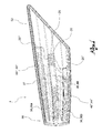
- FIG. 1 shows a perspective view, in an assembled configuration, of a vehicle light according to the present invention
- figure 2 shows a perspective view in separate parts of the light in figure 1 ;
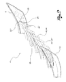
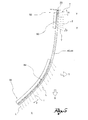
- figure 3 shows a perspective view of several components of the light in figure 1 ;
- FIG. 4-5 show cross-section views of the light in figure 1 .
- reference numeral 4 globally denotes a vehicle light; the definition of vehicle light should be understood in its widest sense, comprising a light suitable for being used on any type of locomotive vehicle.
- vehicle light is understood to mean indifferently a rear vehicle light or a front vehicle light, the latter also known as a headlight.
- the vehicle light 4 comprises a container body 8 and a lenticular body 12 which at least partially define a housing chamber 16 hosting at least one light source 20.
- the light source 20 is electrically connected to electrical connection means to power the same.
- said light source 20 is a light emission diode light source.
- Said light emission diode light source 20 comprises an electric support and connection component 24 and at least one light emission diode 28 connected to said electric support and connection component 24.
- the container body 8 comprises a mouth 32 through which it usually receives and contains the various components of the light 4; the container body 8 further permits the attachment of the light 4 to the relative vehicle.
- the lenticular body is made from at least partially transparent, or semi-transparent or translucid material, and may also comprise an opaque portion.
- the lenticular body 12 is placed so as to close the mouth 32 of the container body 8, so as to enclose said housing chamber 16.
- vehicle light 4 is placed inside the housing chamber 16, such as a reflector body 36, further light sources not shown, and at least one light guide 40.
- the reflector body 36 is usually made from an opaque material and has a substantially concave shape with its inner surface mirror-treated, that is to say metallised.
- the reflector body 36 is, moreover, divided into a first portion 36a and a second portion 36b.
- the first portion 36a of the reflector body 36 extends in a series of shell-shaped reflecting elements 37 and is coupled to a further light source, not shown, comprising a plurality of light emission diode light sources. More specifically, each light emission diode light source is paired with a respective shell-shaped reflecting element 37, so that the beam of light emitted by the light emission diode light source is reflected on the inner metallised surface of the respective shell-shaped reflecting element and projected at a distance after traversing the lenticular body 12. A light of the vehicle light, such as a brake light, is thereby realised.
- the second portion 36b of the reflector body is coupled to a light source, not shown, to make a light of the vehicle light, for example an indicator light
- the light guide 40 comprises a light guide body 44 suitable for receiving the beam of light emitted by the light source 20 so as to collect and propagate within itself the light emitted by the light source 20.
- the light guide body is usually made from a transparent material and bases its functioning principle on the same physical principles which regulate the transmission of light inside optic fibres.
- the light guide body 44 is placed next to the light source 20 so as to collect and propagate within itself the light emitted by said light source. The light propagated inside the light guide body 44 is then extracted and distributed in the surrounding space as desired, as described better below.
- the container body 8, the lenticular body 12, the reflector body 36 and the light guide body 44 are usually made respectively of one or more polymer materials, such as, for example, polycarbonate (PC), polymethyl methacrylate (PMMA) (plexiglass), acrylonitrile butadiene styrene (ABS), APEC, or polypropylene (PP).
- PC polycarbonate
- PMMA polymethyl methacrylate
- ABS acrylonitrile butadiene styrene
- APEC polypropylene
- the light guide 40 is fitted with a plurality of light deviation/extraction elements applied to the light guide body 44, suitable for deviating/extracting the light propagated inside the light guide body 44 outwards of the light guide 40.
- the light guide body 40 extends from a lateral end 52 to a longitudinal end 56 so as to transmit the light between said ends 52, 56, wherein at the lateral end 52 the light guide 40 emits a transversal beam of light, directed in a transversal direction Y-Y, that is perpendicular to a longitudinal or advancement direction X-X of the associable vehicle to which the light 4 is attached. At the longitudinal end 56 the light guide 40 emits a longitudinal beam of light, directed substantially in the longitudinal direction X-X, perpendicular to said transversal direction Y-Y.
- the emission of light in a transversal beam of light fulfils the lateral sidelight function while the emission of light in a longitudinal beam of light fulfils the longitudinal sidelight function (both front or rear).
- transversal Y-Y direction and longitudinal X-X direction should not be understood in a strict sense; in other words the transversal and longitudinal beams of light need not be considered perfectly perpendicular to each other, nor need they be considered perfectly parallel to the transversal and longitudinal directions of the associable vehicle.
- the transversal beam of light must globally perform the lateral sidelight function of the vehicle light.
- the transversal rays of light T of the transversal beam of light are not necessarily all parallel to each other and to the transversal direction.
- the longitudinal beam of light is not necessarily parallel to the direction of driving, that is to say the longitudinal direction X-X but may comprise longitudinal rays of light L which are not necessarily parallel but which are also incident to said longitudinal direction X-X, identifying therewith an angle ⁇ .
- the longitudinal beam of light must globally perform the longitudinal sidelight function.
- the light source 20 is situated near said lateral end 52 of the light guide body 44 so as to emit a luminous beam which is propagated inside the light guide body 44 moving from the lateral end 52 towards the longitudinal end 56.
- the light guide 40 comprises moreover first light deviation/extraction elements 60 which extract the light from the light guide body 44 in a substantially transversal direction Y-Y and towards the lenticular body 12. Said first light deviation/extraction elements 60 thereby create the beam of transversal light directed along the transversal direction Y-Y.
- first light deviation/extraction elements 60 are positioned on the light guide body 44 on the container body side so as to extract the light towards the lenticular body 12, that is outwards of the vehicle light 4.
- the light guide 40 further comprises second light deviation/extraction elements 64 which extract the light from the light guide body 44 in a substantially longitudinal direction X-X and in the direction of the lenticular body 12.
- Said second light deviation/extraction elements 64 thereby create the beam of longitudinal light directed in the longitudinal direction X-X.
- the second light deviation/extraction elements 64 are positioned on the light guide body 44 on the container body side 8 so as to extract the light towards the lenticular body 12, that is outwards of the vehicle light 4.
- the first and second light deviation/extraction elements 60, 64 are direct prisms suitable for encouraging the extraction of the light from the light guide body 44 by means of a single reflection of said light on each single prism.
- the vehicle light 4 comprises a plurality of diffusion elements 68 of the luminous flow, said diffusion elements 68 being positioned between the light guide 40 and the lenticular body 12 so as to receive the transversal beam of light and to expand it in said transversal direction Y-Y according to one or more predefined angles.
- diffusion elements 68 are directly facing the light guide body 44 at a surface of the light guide body opposite that supporting the first light deviation/extraction element 60.
- the diffusion elements 68 are directly facing the lateral end 52 of the light guide 40 and are supported by an intermediate lens 72 positioned between the lenticular body 12 and the light guide 40.
- said diffusion elements 68 are positioned on a terminal strip 76 which identifies a direction of extension S-S incident or inclined to said lateral end 52 of the light guide 40.
- the diffusion elements are oriented on a terminal strip 76 which is not parallel but incident to the first light deviation/extraction elements 60.
- said terminal strip 76 is positioned on a recess 80 made on the intermediate lens 72, said recess 80 extending towards the first light deviation/extraction elements 60.
- said diffusion elements 68 are semi-spherical lenses.
- said diffusion elements 68 are shaped so as to diffuse the luminous flow asymmetrically to said transversal direction Y-Y.
- the luminous flow may be distributed so as not to be perfectly symmetrical to an axis parallel to said transversal direction Y-Y, but to be, for example, asymmetrically projected in the longitudinal direction X-X, in one direction or the other depending on whether the vehicle light is for example rear or front, or in any case according to the design requirements.
- the intermediate lens 72 is transparent at the portions facing the first and second light deviation/extraction elements 60, 64, so as to permit the passage towards the outer lenticular body 12 of the light extracted from the light guide body 44.
- the intermediate lens 72 may also comprise screens, that is, portions opaque to the passage of light, depending on the aesthetic requirements of the vehicle light.
- the light guide 40 in an intermediate portion between said lateral 52 and longitudinal ends 56 is lacking light deviation/extraction elements so as to transmit the light from the lateral end 52 towards the longitudinal end 56 without dispersions of light.
- the light guide 40 has an overall curved pattern substantially like the arc of a circle and/or parabola.
- the vehicle light 4 comprises at least one second light guide 40" , separate from said first light guide 40, the second light guide 40" comprising a second light guide body 44" and a second light source 20" and further light deviation/extraction elements 64" which extract the light in a substantially longitudinal direction X-X.
- the said second light source 20" is electrically connected to said first light source 20 and is positioned near a lateral end 52" of the second light guide 40".
- the vehicle light 4 may also comprise further light guides, such as for example a third light guide 40"' comprising a third light guide body 44"' and light deviation/extraction elements 64"' and relative light sources 20"'.
- a third light guide 40"' comprising a third light guide body 44"' and light deviation/extraction elements 64"' and relative light sources 20"'.
- the vehicle light according to the invention makes it possible to overcome the drawbacks of the prior art presented.
- the vehicle light according to the present invention makes it possible to contemporarily fulfil the function of lateral and longitudinal sidelight, whether front or rear, using a reduced number of components.
- the same light guide is able to provide, by means of the same light source, both the luminous beam for the lateral sidelight and the luminous beam for the longitudinal sidelight.
- the use of two specific and separate light guides or at least two specific and separate luminous sources is thereby avoided.
- the same luminous source used for the two sidelight functions is optimised in terms of energy consumption.
- such luminous source is positioned at the lateral end so as to diffuse the luminous flow through the light guide body, towards the longitudinal end.
- Most of the luminous flow produced by the luminous source must be used for the longitudinal sidelight function and, consequently, the light guide is optimised depending on such longitudinal luminous flow.
- the second light deviation/extraction means are therefore preferably of the direct type that is, they extract the light from the light guide body following a single inner reflection. This way the dispersions of luminous flow are minimal: the emission of the longitudinal flow which, as seen, accounts for the greater part of the flow to be directed outwards of the vehicle light, is thereby optimised.
- transversal flow must comply with specific standards which regulate the angles of aperture, in the longitudinal direction, both forwards and rearwards.
- the solution proposed in the present invention makes it possible to extract the light in a transversal direction, using in this case too, light deviation/extraction elements of the direct type which require a single reflection of the luminous ray.
- This first extraction step thereby entails a high luminous output.
- the subsequent step of opening the beam is equally efficient and permits, thanks to the diffusion elements, an extremely precise control of the geometry of the beam to be extracted. This way the geometry/aperture of the beam of transversal light emitted can be controlled with extreme precision.
Landscapes
- Engineering & Computer Science (AREA)
- General Engineering & Computer Science (AREA)
- Non-Portable Lighting Devices Or Systems Thereof (AREA)
- Lighting Device Outwards From Vehicle And Optical Signal (AREA)
Abstract
Description
- The present invention relates to a vehicle light fitted with at least one front sidelight and at least one lateral sidelight, wherein the term vehicle light is understood to mean indifferently a rear vehicle light or a front vehicle light, the latter also known as a headlight.
- In the same way, the front sidelight is understood to mean a sidelight directed along the longitudinal axis of the vehicle, that is to say, rearwards in the case of a tail light or forwards in the case of a front light or headlight.
- As is known, a vehicle light is a lighting and/or signalling device of a vehicle comprising at least one outer light of the vehicle having a lighting or signalling function outwards of the vehicle.
- The vehicle light, in its simplest form comprises a container body, a lenticular body and at least one light source.
- The lenticular body is placed so as to close a mouth of the container body so as to form a housing chamber. The light source is arranged inside the housing chamber, which may be directed so as to emit light towards the lenticular body, when powered with electricity.
- Vehicle lights are provided with at least one rear or front sidelight and, in some cases, may be provided with at least one lateral rear or front sidelight.
- The sidelight, whether front or rear, is generally used to signal the presence of the vehicle to which it is applied.
- The rear or front lateral sidelight is used for example to indicate to others the lateral dimensions of the vehicle.
- The co-presence of rear/front and lateral sidelights in the same rear/front vehicle light entails some construction complications of the vehicle light. In fact, the longitudinal and transversal luminous beams (whether rear or front) must comply with legal specifications both in terms of luminous power and of geometrics, that is to say the aperture of the luminous beam produced.
- The solutions of the prior art envisage the use of specific and separate light sources for performing the longitudinal and lateral sidelight functions: in other words, the light sources used for the rear/front sidelights are different from those used for the transversal sidelights.
- Such solutions of the prior art are therefore expensive to manufacture in that they envisage a large number of components, increasing the production and assembly costs of the lights.
- The purpose of the present invention is to make a vehicle light provided with at least one rear/front sidelight and at least one lateral sidelight, which has reduced manufacturing and functioning costs.
- Such purpose is achieved by a vehicle light according to claim 1.
- Other embodiments of the vehicle light according to the invention are described in the subsequent claims.
- Further characteristics and advantages of the present invention will be more clearly comprehensible from the description given below of its preferred and non-limiting embodiments, wherein:
- -
figure 1 shows a perspective view, in an assembled configuration, of a vehicle light according to the present invention; - -
figure 2 shows a perspective view in separate parts of the light infigure 1 ; - -
figure 3 shows a perspective view of several components of the light infigure 1 ; - -
figures 4-5 show cross-section views of the light infigure 1 . - The elements or parts of elements common to the embodiments described below will be indicated using the same reference numerals.
- With reference to the aforementioned figures,
reference numeral 4 globally denotes a vehicle light; the definition of vehicle light should be understood in its widest sense, comprising a light suitable for being used on any type of locomotive vehicle. The term vehicle light is understood to mean indifferently a rear vehicle light or a front vehicle light, the latter also known as a headlight. - The
vehicle light 4 comprises acontainer body 8 and alenticular body 12 which at least partially define ahousing chamber 16 hosting at least onelight source 20. - The
light source 20 is electrically connected to electrical connection means to power the same. - Preferably, said
light source 20 is a light emission diode light source. Said light emissiondiode light source 20 comprises an electric support andconnection component 24 and at least onelight emission diode 28 connected to said electric support andconnection component 24. - The
container body 8 comprises amouth 32 through which it usually receives and contains the various components of thelight 4; thecontainer body 8 further permits the attachment of thelight 4 to the relative vehicle. - The lenticular body is made from at least partially transparent, or semi-transparent or translucid material, and may also comprise an opaque portion.
- The
lenticular body 12 is placed so as to close themouth 32 of thecontainer body 8, so as to enclose saidhousing chamber 16. - Further components of the
vehicle light 4 are placed inside thehousing chamber 16, such as areflector body 36, further light sources not shown, and at least onelight guide 40. - The
reflector body 36 is usually made from an opaque material and has a substantially concave shape with its inner surface mirror-treated, that is to say metallised. Thereflector body 36 is, moreover, divided into a first portion 36a and a second portion 36b. The first portion 36a of thereflector body 36 extends in a series of shell-shaped reflecting elements 37 and is coupled to a further light source, not shown, comprising a plurality of light emission diode light sources. More specifically, each light emission diode light source is paired with a respective shell-shaped reflectingelement 37, so that the beam of light emitted by the light emission diode light source is reflected on the inner metallised surface of the respective shell-shaped reflecting element and projected at a distance after traversing thelenticular body 12. A light of the vehicle light, such as a brake light, is thereby realised. Similarly the second portion 36b of the reflector body is coupled to a light source, not shown, to make a light of the vehicle light, for example an indicator light. - The
light guide 40 comprises alight guide body 44 suitable for receiving the beam of light emitted by thelight source 20 so as to collect and propagate within itself the light emitted by thelight source 20. - The light guide body is usually made from a transparent material and bases its functioning principle on the same physical principles which regulate the transmission of light inside optic fibres. The
light guide body 44 is placed next to thelight source 20 so as to collect and propagate within itself the light emitted by said light source. The light propagated inside thelight guide body 44 is then extracted and distributed in the surrounding space as desired, as described better below. - The
container body 8, thelenticular body 12, thereflector body 36 and thelight guide body 44 are usually made respectively of one or more polymer materials, such as, for example, polycarbonate (PC), polymethyl methacrylate (PMMA) (plexiglass), acrylonitrile butadiene styrene (ABS), APEC, or polypropylene (PP). - The
light guide 40 is fitted with a plurality of light deviation/extraction elements applied to thelight guide body 44, suitable for deviating/extracting the light propagated inside thelight guide body 44 outwards of thelight guide 40. - The
light guide body 40 extends from alateral end 52 to alongitudinal end 56 so as to transmit the light between saidends lateral end 52 thelight guide 40 emits a transversal beam of light, directed in a transversal direction Y-Y, that is perpendicular to a longitudinal or advancement direction X-X of the associable vehicle to which thelight 4 is attached. At thelongitudinal end 56 thelight guide 40 emits a longitudinal beam of light, directed substantially in the longitudinal direction X-X, perpendicular to said transversal direction Y-Y. - The emission of light in a transversal beam of light fulfils the lateral sidelight function while the emission of light in a longitudinal beam of light fulfils the longitudinal sidelight function (both front or rear).
- The definition of the transversal Y-Y direction and longitudinal X-X direction should not be understood in a strict sense; in other words the transversal and longitudinal beams of light need not be considered perfectly perpendicular to each other, nor need they be considered perfectly parallel to the transversal and longitudinal directions of the associable vehicle.
- The transversal beam of light must globally perform the lateral sidelight function of the vehicle light.
- Despite this, the transversal rays of light T of the transversal beam of light are not necessarily all parallel to each other and to the transversal direction. For example, there may be, for design requirements, transversal rays of light T angled in relation to said transversal direction Y-Y according to angles of incidence α and
- β even opposite to each other (
figure 5 ). - The longitudinal beam of light is not necessarily parallel to the direction of driving, that is to say the longitudinal direction X-X but may comprise longitudinal rays of light L which are not necessarily parallel but which are also incident to said longitudinal direction X-X, identifying therewith an angle γ. In other words, the longitudinal beam of light must globally perform the longitudinal sidelight function.
- Advantageously, the
light source 20 is situated near saidlateral end 52 of thelight guide body 44 so as to emit a luminous beam which is propagated inside thelight guide body 44 moving from thelateral end 52 towards thelongitudinal end 56. - Advantageously, at said
lateral end 52 thelight guide 40 comprises moreover first light deviation/extraction elements 60 which extract the light from thelight guide body 44 in a substantially transversal direction Y-Y and towards thelenticular body 12. Said first light deviation/extraction elements 60 thereby create the beam of transversal light directed along the transversal direction Y-Y. - In particular the first light deviation/
extraction elements 60 are positioned on thelight guide body 44 on the container body side so as to extract the light towards thelenticular body 12, that is outwards of thevehicle light 4. - Advantageously, at the
longitudinal end 56 thelight guide 40 further comprises second light deviation/extraction elements 64 which extract the light from thelight guide body 44 in a substantially longitudinal direction X-X and in the direction of thelenticular body 12. - Said second light deviation/
extraction elements 64 thereby create the beam of longitudinal light directed in the longitudinal direction X-X. - In particular the second light deviation/
extraction elements 64 are positioned on thelight guide body 44 on thecontainer body side 8 so as to extract the light towards thelenticular body 12, that is outwards of thevehicle light 4. - Preferably, the first and second light deviation/
extraction elements light guide body 44 by means of a single reflection of said light on each single prism. - At the
lateral end 52, thevehicle light 4 comprises a plurality ofdiffusion elements 68 of the luminous flow, saiddiffusion elements 68 being positioned between thelight guide 40 and thelenticular body 12 so as to receive the transversal beam of light and to expand it in said transversal direction Y-Y according to one or more predefined angles. - In particular the
diffusion elements 68 are directly facing thelight guide body 44 at a surface of the light guide body opposite that supporting the first light deviation/extraction element 60. - The
diffusion elements 68 are directly facing thelateral end 52 of thelight guide 40 and are supported by anintermediate lens 72 positioned between thelenticular body 12 and thelight guide 40. - According to one embodiment, said
diffusion elements 68 are positioned on aterminal strip 76 which identifies a direction of extension S-S incident or inclined to saidlateral end 52 of thelight guide 40. - In other words, the diffusion elements are oriented on a
terminal strip 76 which is not parallel but incident to the first light deviation/extraction elements 60. - According to one embodiment, said
terminal strip 76 is positioned on arecess 80 made on theintermediate lens 72, saidrecess 80 extending towards the first light deviation/extraction elements 60. - According to one embodiment, said
diffusion elements 68 are semi-spherical lenses. - According to one embodiment, said
diffusion elements 68 are shaped so as to diffuse the luminous flow asymmetrically to said transversal direction Y-Y. In other words, the luminous flow may be distributed so as not to be perfectly symmetrical to an axis parallel to said transversal direction Y-Y, but to be, for example, asymmetrically projected in the longitudinal direction X-X, in one direction or the other depending on whether the vehicle light is for example rear or front, or in any case according to the design requirements. - In yet other words, with reference to
figure 5 , there may be, for design requirements, rays of transversal light T at an angle to said transversal direction Y-Y according to angles of incidence α and β not only opposite each other in the longitudinal direction X-X but also different from each other in terms of breadth. - The
intermediate lens 72 is transparent at the portions facing the first and second light deviation/extraction elements lenticular body 12 of the light extracted from thelight guide body 44. - The
intermediate lens 72 may also comprise screens, that is, portions opaque to the passage of light, depending on the aesthetic requirements of the vehicle light. - Preferably, the
light guide 40, in an intermediate portion between said lateral 52 and longitudinal ends 56 is lacking light deviation/extraction elements so as to transmit the light from thelateral end 52 towards thelongitudinal end 56 without dispersions of light. - The
light guide 40 has an overall curved pattern substantially like the arc of a circle and/or parabola. - According to one embodiment, the
vehicle light 4 according to the present invention comprises at least onesecond light guide 40" , separate from saidfirst light guide 40, the secondlight guide 40" comprising a secondlight guide body 44" and a secondlight source 20" and further light deviation/extraction elements 64" which extract the light in a substantially longitudinal direction X-X. - Preferably, the said second
light source 20" is electrically connected to saidfirst light source 20 and is positioned near alateral end 52" of the secondlight guide 40". - The
vehicle light 4 may also comprise further light guides, such as for example a thirdlight guide 40"' comprising a thirdlight guide body 44"' and light deviation/extraction elements 64"' and relativelight sources 20"'. - As may be seen from the description, the vehicle light according to the invention makes it possible to overcome the drawbacks of the prior art presented.
- In fact, unlike the solutions of the prior art, the vehicle light according to the present invention makes it possible to contemporarily fulfil the function of lateral and longitudinal sidelight, whether front or rear, using a reduced number of components.
- In particular the same light guide is able to provide, by means of the same light source, both the luminous beam for the lateral sidelight and the luminous beam for the longitudinal sidelight. The use of two specific and separate light guides or at least two specific and separate luminous sources is thereby avoided.
- This way the construction of the vehicle light is simplified, and is therefore more economical to manufacture and to assemble. Moreover, the energy consumption is also reduced since the same light source fulfils the two aforementioned sidelight functions.
- It is to be noted that, the same luminous source used for the two sidelight functions is optimised in terms of energy consumption. In fact, such luminous source is positioned at the lateral end so as to diffuse the luminous flow through the light guide body, towards the longitudinal end. Most of the luminous flow produced by the luminous source must be used for the longitudinal sidelight function and, consequently, the light guide is optimised depending on such longitudinal luminous flow. The second light deviation/extraction means are therefore preferably of the direct type that is, they extract the light from the light guide body following a single inner reflection. This way the dispersions of luminous flow are minimal: the emission of the longitudinal flow which, as seen, accounts for the greater part of the flow to be directed outwards of the vehicle light, is thereby optimised.
- Moreover, as regards the lateral sidelight, it may be observed that the respective flow of transversal light is also optimised.
- In fact, the transversal flow must comply with specific standards which regulate the angles of aperture, in the longitudinal direction, both forwards and rearwards.
- It has thus been found that the extraction of the luminous beam in a substantially transversal direction and its subsequent diffusion in a longitudinal direction permits a higher energy efficiency compared to the solution of extracting the flow directly in a conical beam.
- In fact, the solution proposed in the present invention makes it possible to extract the light in a transversal direction, using in this case too, light deviation/extraction elements of the direct type which require a single reflection of the luminous ray.
- This first extraction step thereby entails a high luminous output. The subsequent step of opening the beam is equally efficient and permits, thanks to the diffusion elements, an extremely precise control of the geometry of the beam to be extracted. This way the geometry/aperture of the beam of transversal light emitted can be controlled with extreme precision.
- A person skilled in the art may make numerous modifications and variations to the vehicles lights described above so as to satisfy contingent and specific requirements, while remaining within the sphere of protection of the invention as defined by the following claims.
Claims (15)
- Vehicle light (4) comprising- a container body (8) and a lenticular body (12) which at least partially define a housing chamber (16) hosting at least one light source (20),- said light source (20) being electrically connected to electrical connection means to power the same,- wherein said vehicle light (4) comprises at least one light guide (40) having a light guide body (44) suitable for receiving the beam of light from the light source (20) so as to collect and propagate within itself the light emitted by the light source (20),- wherein the light guide (40) is fitted with a plurality of light deviation/extraction elements (60, 64) applied to the light guide body (44), suitable for deviating/extracting the light propagated inside the light guide body (44) outwards of the light guide (40), characterised in that- said light guide body (44) extends from a lateral end (52) to a longitudinal end (56) so as to transmit the light between said ends (52, 56), wherein at the lateral end (52) the light guide (40) emits a transversal beam of light, directed in a transversal direction (Y-Y), that is, perpendicular to a longitudinal or advancement direction (X-X) of the associable vehicle to which the light (4) is attached, and wherein at the longitudinal end (56) the light guide body (44) emits a longitudinal beam of light directed substantially in the direction of advancement (X-X) perpendicular to said transversal direction (Y-Y),- wherein the light source (20) is situated near said lateral end (52) so as to emit a luminous beam which is propagated inside the light guide body (44) moving from the lateral end (52) towards the longitudinal end (56),- wherein at the lateral end (52) the light guide (40) comprises first light deviation/extraction elements (60) which extract the light from the light guide (40) in a substantially transversal direction (Y-Y) and in the direction of the lenticular body (12),- wherein at the longitudinal end (56) the light guide (40) comprises second light deviation/extraction elements (64) which extract the light from the light guide (40) in a substantially longitudinal direction (X-X) and in the direction of the lenticular body (12).
- Vehicle light (4) according to claim 1, wherein the first and second light deviation/extraction elements (60,64), are direct prisms suitable for encouraging the extraction of the light from the light guide body (44) by means of a single reflection of said light on each single prism.
- Vehicle light (4) according to claim 1 or 2, wherein at the lateral end (52), the light (4) comprises a plurality of diffusion elements (68) of the luminous flow, said diffusion elements (68) being positioned between the light guide (40) and the lenticular body (12) so as to receive the transversal beam of light and to expand it in said transversal direction (Y-Y) at one or more predefined aperture angles.
- Vehicle light (4) according to claim 3, wherein said diffusion elements (68) are directly facing the lateral end (52) of the light guide (40) and are supported by an intermediate lens (72) positioned between the lenticular body (12) and the light guide (40).
- Vehicle light (4) according to claim 3 or 4, wherein said diffusion elements (68) are positioned on a terminal strip (76) which identifies a direction of extension (S-S) incident or inclined to said lateral end (52) of the light guide (40).
- Vehicle light (4) according to claim 5, wherein said terminal strip (76) is positioned on a recess (80) made on the intermediate lens (72), said recess (80) extending towards the first light deviation/extraction elements (60).
- Vehicle light (4) according to any of the claims from 3 to 6 wherein said diffusion elements (68) are semi-spherical lenses.
- Vehicle light (4) according to any of the claims from 3 to 7 wherein said diffusion elements (68) are shaped so as to diffuse the luminous flow asymmetrically to said transversal direction (Y-Y).
- Vehicle light (4) according to any of the claims from 4 to 8 wherein said intermediate lens (72) is transparent at the portions facing the first and second light deviation/extraction elements (60,64), so as to permit the passage towards the outer lenticular body (12) of the light extracted from the light guide body (44).
- Vehicle light (4) according to any of the previous claims, wherein the light source (20) is a light source comprising at least one light-emitting diode (28).
- Vehicle light (4) according to any of the previous claims, wherein the light guide (40), in an intermediate portion between said lateral and longitudinal ends (52,56) is lacking light deviation/extraction elements, so as to transmit the light from the lateral end (52) towards the longitudinal end (56) without dispersions of light.
- Vehicle light (4) according to any of the previous claims, wherein the light guide (40) has a curved pattern substantially like the arc of a circle and/or parabola.
- Vehicle light (4) according to any of the previous claims, wherein said vehicle light (4) comprises at least one second light guide (40"), separate from said first light guide (40), the second light guide (40") comprising a second light guide body (44") and being provided with a second light source (20") and further light deviation/extraction elements (64") which extract the light in a substantially longitudinal direction (X-X).
- Vehicle light (4) according to claim 13, wherein said second light source (20") is electrically connected to said first light source (20) and is positioned near a lateral end (52") of the second light guide (40").
- Vehicle light (4) according to claim 13 or 14, wherein the light (4) comprises a third light guide (40"') having a third light guide body (44"') and light deviation/extraction elements (64"') and relative light sources (20'''), wherein said third light source (20''') is electrically connected to said first and second light sources (20',20").
Priority Applications (1)
| Application Number | Priority Date | Filing Date | Title |
|---|---|---|---|
| PL12198731T PL2607777T3 (en) | 2011-12-21 | 2012-12-20 | Vehicle light |
Applications Claiming Priority (1)
| Application Number | Priority Date | Filing Date | Title |
|---|---|---|---|
| ITPD20110403 | 2011-12-21 |
Publications (2)
| Publication Number | Publication Date |
|---|---|
| EP2607777A1 true EP2607777A1 (en) | 2013-06-26 |
| EP2607777B1 EP2607777B1 (en) | 2020-10-28 |
Family
ID=47358416
Family Applications (1)
| Application Number | Title | Priority Date | Filing Date |
|---|---|---|---|
| EP12198731.7A Active EP2607777B1 (en) | 2011-12-21 | 2012-12-20 | Vehicle light |
Country Status (3)
| Country | Link |
|---|---|
| EP (1) | EP2607777B1 (en) |
| ES (1) | ES2835184T3 (en) |
| PL (1) | PL2607777T3 (en) |
Cited By (8)
| Publication number | Priority date | Publication date | Assignee | Title |
|---|---|---|---|---|
| EP3208525A1 (en) * | 2016-02-17 | 2017-08-23 | ZKW Group GmbH | Light guide for a vehicle headlight |
| IT201600098165A1 (en) * | 2016-09-30 | 2018-03-30 | Automotive Lighting Italia Spa | AUTOMOTIVE HEADLIGHT |
| GB2554403A (en) * | 2016-09-05 | 2018-04-04 | Jaguar Land Rover Ltd | A lamp assembly for an automobile, a headlamp comprising such a lamp assembly, and an automobile comprising such a lamp assembly |
| EP3450834A1 (en) * | 2017-08-29 | 2019-03-06 | ZKW Group GmbH | Lighting and/or signalling device for a motor vehicle |
| CN110073142A (en) * | 2016-12-23 | 2019-07-30 | 亮锐控股有限公司 | The light emitting module with light guide plate for automobile headlamp |
| CN110958960A (en) * | 2017-07-21 | 2020-04-03 | 魏德塑料有限责任公司 | Component for a vehicle |
| CN114673962A (en) * | 2022-03-31 | 2022-06-28 | 重庆长安新能源汽车科技有限公司 | Dynamic running water car light and vehicle |
| EP3450253B1 (en) * | 2017-08-29 | 2024-05-15 | ZKW Group GmbH | Lighting and/or signalling device for a motor vehicle |
Citations (7)
| Publication number | Priority date | Publication date | Assignee | Title |
|---|---|---|---|---|
| EP1022187A2 (en) * | 1999-01-21 | 2000-07-26 | FER Fahrzeugelektrik GmbH | Vehicle light |
| DE10332977A1 (en) * | 2003-07-21 | 2005-07-07 | Hella Kgaa Hueck & Co. | Motor vehicle light, has additional filament which is arranged relative to light entrance surface |
| EP1898147A1 (en) * | 2006-09-11 | 2008-03-12 | Hella KG Hueck & Co. | Lighting device for vehicle |
| US20100254152A1 (en) * | 2009-04-03 | 2010-10-07 | Amine Taleb-Bendiab | Dual-direction light pipe for automotive lighting |
| EP2258977A2 (en) * | 2009-06-05 | 2010-12-08 | Koito Manufacturing Co., Ltd. | Vehicular lamp |
| EP2292466A1 (en) * | 2009-09-04 | 2011-03-09 | Koito Manufacturing Co., Ltd. | Side turn signal lamp |
| DE102010006348A1 (en) * | 2010-01-30 | 2011-08-04 | Hella KGaA Hueck & Co., 59557 | Illumination device for car, has two light units comprising two planar light guide elements, respectively, where back sides and/or front sides of guide elements are provided with same uncoupling element |
-
2012
- 2012-12-20 PL PL12198731T patent/PL2607777T3/en unknown
- 2012-12-20 ES ES12198731T patent/ES2835184T3/en active Active
- 2012-12-20 EP EP12198731.7A patent/EP2607777B1/en active Active
Patent Citations (7)
| Publication number | Priority date | Publication date | Assignee | Title |
|---|---|---|---|---|
| EP1022187A2 (en) * | 1999-01-21 | 2000-07-26 | FER Fahrzeugelektrik GmbH | Vehicle light |
| DE10332977A1 (en) * | 2003-07-21 | 2005-07-07 | Hella Kgaa Hueck & Co. | Motor vehicle light, has additional filament which is arranged relative to light entrance surface |
| EP1898147A1 (en) * | 2006-09-11 | 2008-03-12 | Hella KG Hueck & Co. | Lighting device for vehicle |
| US20100254152A1 (en) * | 2009-04-03 | 2010-10-07 | Amine Taleb-Bendiab | Dual-direction light pipe for automotive lighting |
| EP2258977A2 (en) * | 2009-06-05 | 2010-12-08 | Koito Manufacturing Co., Ltd. | Vehicular lamp |
| EP2292466A1 (en) * | 2009-09-04 | 2011-03-09 | Koito Manufacturing Co., Ltd. | Side turn signal lamp |
| DE102010006348A1 (en) * | 2010-01-30 | 2011-08-04 | Hella KGaA Hueck & Co., 59557 | Illumination device for car, has two light units comprising two planar light guide elements, respectively, where back sides and/or front sides of guide elements are provided with same uncoupling element |
Cited By (12)
| Publication number | Priority date | Publication date | Assignee | Title |
|---|---|---|---|---|
| EP3208525A1 (en) * | 2016-02-17 | 2017-08-23 | ZKW Group GmbH | Light guide for a vehicle headlight |
| GB2554403A (en) * | 2016-09-05 | 2018-04-04 | Jaguar Land Rover Ltd | A lamp assembly for an automobile, a headlamp comprising such a lamp assembly, and an automobile comprising such a lamp assembly |
| GB2554403B (en) * | 2016-09-05 | 2019-10-09 | Jaguar Land Rover Ltd | A lamp assembly for an automobile, a headlamp comprising such a lamp assembly, and an automobile comprising such a lamp assembly |
| IT201600098165A1 (en) * | 2016-09-30 | 2018-03-30 | Automotive Lighting Italia Spa | AUTOMOTIVE HEADLIGHT |
| EP3301352A1 (en) * | 2016-09-30 | 2018-04-04 | Automotive Lighting Italia S.p.A. | Vehicle light |
| CN110073142A (en) * | 2016-12-23 | 2019-07-30 | 亮锐控股有限公司 | The light emitting module with light guide plate for automobile headlamp |
| CN110073142B (en) * | 2016-12-23 | 2021-06-01 | 亮锐控股有限公司 | Light module with light guide plate for a motor vehicle headlight |
| CN110958960A (en) * | 2017-07-21 | 2020-04-03 | 魏德塑料有限责任公司 | Component for a vehicle |
| EP3450834A1 (en) * | 2017-08-29 | 2019-03-06 | ZKW Group GmbH | Lighting and/or signalling device for a motor vehicle |
| EP3450253B1 (en) * | 2017-08-29 | 2024-05-15 | ZKW Group GmbH | Lighting and/or signalling device for a motor vehicle |
| CN114673962A (en) * | 2022-03-31 | 2022-06-28 | 重庆长安新能源汽车科技有限公司 | Dynamic running water car light and vehicle |
| CN114673962B (en) * | 2022-03-31 | 2024-02-02 | 深蓝汽车科技有限公司 | Dynamic running water car light and vehicle |
Also Published As
| Publication number | Publication date |
|---|---|
| PL2607777T3 (en) | 2021-07-05 |
| ES2835184T3 (en) | 2021-06-22 |
| EP2607777B1 (en) | 2020-10-28 |
Similar Documents
| Publication | Publication Date | Title |
|---|---|---|
| EP2607777B1 (en) | Vehicle light | |
| JP4930787B2 (en) | VEHICLE LIGHT AND LIGHT GUIDE LENS USED FOR VEHICLE LIGHT | |
| JP6029298B2 (en) | Vehicle lighting | |
| JP6560514B2 (en) | Vehicle lighting | |
| JP5363235B2 (en) | Vehicle lighting | |
| CN110360525B (en) | Vehicle lamp | |
| JP7081977B2 (en) | Vehicle lighting | |
| JP2007180027A (en) | Lighting or signalling device with optical guide for automobile | |
| EP3502552B1 (en) | Vehicle light with portions at different luminance levels | |
| CN102840529A (en) | Reflector signal lamp having hidden light source | |
| JP5255947B2 (en) | Vehicle lamp | |
| EP2669721A1 (en) | Lighting device for vehicles | |
| JP2016152142A (en) | Vehicular lighting fixture | |
| JP6466440B2 (en) | Lighting system with integrated LEDs, especially for automotive lighting components | |
| JP6221438B2 (en) | Vehicle lighting | |
| JP2014099324A (en) | Lamp for vehicle | |
| EP2748658A1 (en) | Led rear lamp, in particular for a bicycle | |
| JP2016212988A (en) | Vehicular lamp | |
| KR101910356B1 (en) | Vehicle lamp with an inner component | |
| JP2016024855A (en) | Vehicular signal lamp | |
| KR20110040070A (en) | Lamp for vehicle | |
| JP5563210B2 (en) | Lamp | |
| JP4898557B2 (en) | Vehicle lighting | |
| JP6054724B2 (en) | Vehicle signal lights | |
| JP5363179B2 (en) | Vehicle lighting |
Legal Events
| Date | Code | Title | Description |
|---|---|---|---|
| AK | Designated contracting states |
Kind code of ref document: A1 Designated state(s): AL AT BE BG CH CY CZ DE DK EE ES FI FR GB GR HR HU IE IS IT LI LT LU LV MC MK MT NL NO PL PT RO RS SE SI SK SM TR |
|
| AX | Request for extension of the european patent |
Extension state: BA ME |
|
| PUAI | Public reference made under article 153(3) epc to a published international application that has entered the european phase |
Free format text: ORIGINAL CODE: 0009012 |
|
| 17P | Request for examination filed |
Effective date: 20131219 |
|
| RBV | Designated contracting states (corrected) |
Designated state(s): AL AT BE BG CH CY CZ DE DK EE ES FI FR GB GR HR HU IE IS IT LI LT LU LV MC MK MT NL NO PL PT RO RS SE SI SK SM TR |
|
| STAA | Information on the status of an ep patent application or granted ep patent |
Free format text: STATUS: EXAMINATION IS IN PROGRESS |
|
| 17Q | First examination report despatched |
Effective date: 20191016 |
|
| REG | Reference to a national code |
Ref country code: DE Ref legal event code: R079 Ref document number: 602012072970 Country of ref document: DE Free format text: PREVIOUS MAIN CLASS: F21S0008100000 Ipc: F21S0043237000 |
|
| RIC1 | Information provided on ipc code assigned before grant |
Ipc: F21S 43/245 20180101ALI20200420BHEP Ipc: F21S 43/249 20180101ALI20200420BHEP Ipc: F21S 43/237 20180101AFI20200420BHEP Ipc: F21Y 115/10 20160101ALN20200420BHEP |
|
| GRAP | Despatch of communication of intention to grant a patent |
Free format text: ORIGINAL CODE: EPIDOSNIGR1 |
|
| STAA | Information on the status of an ep patent application or granted ep patent |
Free format text: STATUS: GRANT OF PATENT IS INTENDED |
|
| RAP1 | Party data changed (applicant data changed or rights of an application transferred) |
Owner name: MARELLI AUTOMOTIVE LIGHTING ITALY S.P.A. |
|
| INTG | Intention to grant announced |
Effective date: 20200529 |
|
| GRAS | Grant fee paid |
Free format text: ORIGINAL CODE: EPIDOSNIGR3 |
|
| GRAA | (expected) grant |
Free format text: ORIGINAL CODE: 0009210 |
|
| STAA | Information on the status of an ep patent application or granted ep patent |
Free format text: STATUS: THE PATENT HAS BEEN GRANTED |
|
| AK | Designated contracting states |
Kind code of ref document: B1 Designated state(s): AL AT BE BG CH CY CZ DE DK EE ES FI FR GB GR HR HU IE IS IT LI LT LU LV MC MK MT NL NO PL PT RO RS SE SI SK SM TR |
|
| REG | Reference to a national code |
Ref country code: GB Ref legal event code: FG4D |
|
| REG | Reference to a national code |
Ref country code: CH Ref legal event code: EP |
|
| REG | Reference to a national code |
Ref country code: DE Ref legal event code: R096 Ref document number: 602012072970 Country of ref document: DE |
|
| REG | Reference to a national code |
Ref country code: AT Ref legal event code: REF Ref document number: 1328583 Country of ref document: AT Kind code of ref document: T Effective date: 20201115 |
|
| REG | Reference to a national code |
Ref country code: IE Ref legal event code: FG4D |
|
| REG | Reference to a national code |
Ref country code: AT Ref legal event code: MK05 Ref document number: 1328583 Country of ref document: AT Kind code of ref document: T Effective date: 20201028 |
|
| REG | Reference to a national code |
Ref country code: NL Ref legal event code: MP Effective date: 20201028 |
|
| PG25 | Lapsed in a contracting state [announced via postgrant information from national office to epo] |
Ref country code: NL Free format text: LAPSE BECAUSE OF FAILURE TO SUBMIT A TRANSLATION OF THE DESCRIPTION OR TO PAY THE FEE WITHIN THE PRESCRIBED TIME-LIMIT Effective date: 20201028 Ref country code: PT Free format text: LAPSE BECAUSE OF FAILURE TO SUBMIT A TRANSLATION OF THE DESCRIPTION OR TO PAY THE FEE WITHIN THE PRESCRIBED TIME-LIMIT Effective date: 20210301 Ref country code: NO Free format text: LAPSE BECAUSE OF FAILURE TO SUBMIT A TRANSLATION OF THE DESCRIPTION OR TO PAY THE FEE WITHIN THE PRESCRIBED TIME-LIMIT Effective date: 20210128 Ref country code: RS Free format text: LAPSE BECAUSE OF FAILURE TO SUBMIT A TRANSLATION OF THE DESCRIPTION OR TO PAY THE FEE WITHIN THE PRESCRIBED TIME-LIMIT Effective date: 20201028 Ref country code: FI Free format text: LAPSE BECAUSE OF FAILURE TO SUBMIT A TRANSLATION OF THE DESCRIPTION OR TO PAY THE FEE WITHIN THE PRESCRIBED TIME-LIMIT Effective date: 20201028 Ref country code: GR Free format text: LAPSE BECAUSE OF FAILURE TO SUBMIT A TRANSLATION OF THE DESCRIPTION OR TO PAY THE FEE WITHIN THE PRESCRIBED TIME-LIMIT Effective date: 20210129 |
|
| REG | Reference to a national code |
Ref country code: LT Ref legal event code: MG4D |
|
| PG25 | Lapsed in a contracting state [announced via postgrant information from national office to epo] |
Ref country code: IS Free format text: LAPSE BECAUSE OF FAILURE TO SUBMIT A TRANSLATION OF THE DESCRIPTION OR TO PAY THE FEE WITHIN THE PRESCRIBED TIME-LIMIT Effective date: 20210228 Ref country code: LV Free format text: LAPSE BECAUSE OF FAILURE TO SUBMIT A TRANSLATION OF THE DESCRIPTION OR TO PAY THE FEE WITHIN THE PRESCRIBED TIME-LIMIT Effective date: 20201028 Ref country code: SE Free format text: LAPSE BECAUSE OF FAILURE TO SUBMIT A TRANSLATION OF THE DESCRIPTION OR TO PAY THE FEE WITHIN THE PRESCRIBED TIME-LIMIT Effective date: 20201028 Ref country code: BG Free format text: LAPSE BECAUSE OF FAILURE TO SUBMIT A TRANSLATION OF THE DESCRIPTION OR TO PAY THE FEE WITHIN THE PRESCRIBED TIME-LIMIT Effective date: 20210128 Ref country code: AT Free format text: LAPSE BECAUSE OF FAILURE TO SUBMIT A TRANSLATION OF THE DESCRIPTION OR TO PAY THE FEE WITHIN THE PRESCRIBED TIME-LIMIT Effective date: 20201028 |
|
| REG | Reference to a national code |
Ref country code: ES Ref legal event code: FG2A Ref document number: 2835184 Country of ref document: ES Kind code of ref document: T3 Effective date: 20210622 |
|
| PG25 | Lapsed in a contracting state [announced via postgrant information from national office to epo] |
Ref country code: HR Free format text: LAPSE BECAUSE OF FAILURE TO SUBMIT A TRANSLATION OF THE DESCRIPTION OR TO PAY THE FEE WITHIN THE PRESCRIBED TIME-LIMIT Effective date: 20201028 |
|
| REG | Reference to a national code |
Ref country code: DE Ref legal event code: R097 Ref document number: 602012072970 Country of ref document: DE |
|
| PG25 | Lapsed in a contracting state [announced via postgrant information from national office to epo] |
Ref country code: SM Free format text: LAPSE BECAUSE OF FAILURE TO SUBMIT A TRANSLATION OF THE DESCRIPTION OR TO PAY THE FEE WITHIN THE PRESCRIBED TIME-LIMIT Effective date: 20201028 Ref country code: EE Free format text: LAPSE BECAUSE OF FAILURE TO SUBMIT A TRANSLATION OF THE DESCRIPTION OR TO PAY THE FEE WITHIN THE PRESCRIBED TIME-LIMIT Effective date: 20201028 Ref country code: RO Free format text: LAPSE BECAUSE OF FAILURE TO SUBMIT A TRANSLATION OF THE DESCRIPTION OR TO PAY THE FEE WITHIN THE PRESCRIBED TIME-LIMIT Effective date: 20201028 Ref country code: SK Free format text: LAPSE BECAUSE OF FAILURE TO SUBMIT A TRANSLATION OF THE DESCRIPTION OR TO PAY THE FEE WITHIN THE PRESCRIBED TIME-LIMIT Effective date: 20201028 Ref country code: LT Free format text: LAPSE BECAUSE OF FAILURE TO SUBMIT A TRANSLATION OF THE DESCRIPTION OR TO PAY THE FEE WITHIN THE PRESCRIBED TIME-LIMIT Effective date: 20201028 |
|
| REG | Reference to a national code |
Ref country code: CH Ref legal event code: PL |
|
| PG25 | Lapsed in a contracting state [announced via postgrant information from national office to epo] |
Ref country code: DK Free format text: LAPSE BECAUSE OF FAILURE TO SUBMIT A TRANSLATION OF THE DESCRIPTION OR TO PAY THE FEE WITHIN THE PRESCRIBED TIME-LIMIT Effective date: 20201028 Ref country code: MC Free format text: LAPSE BECAUSE OF FAILURE TO SUBMIT A TRANSLATION OF THE DESCRIPTION OR TO PAY THE FEE WITHIN THE PRESCRIBED TIME-LIMIT Effective date: 20201028 |
|
| PLBE | No opposition filed within time limit |
Free format text: ORIGINAL CODE: 0009261 |
|
| REG | Reference to a national code |
Ref country code: BE Ref legal event code: MM Effective date: 20201231 |
|
| STAA | Information on the status of an ep patent application or granted ep patent |
Free format text: STATUS: NO OPPOSITION FILED WITHIN TIME LIMIT |
|
| 26N | No opposition filed |
Effective date: 20210729 |
|
| PG25 | Lapsed in a contracting state [announced via postgrant information from national office to epo] |
Ref country code: AL Free format text: LAPSE BECAUSE OF FAILURE TO SUBMIT A TRANSLATION OF THE DESCRIPTION OR TO PAY THE FEE WITHIN THE PRESCRIBED TIME-LIMIT Effective date: 20201028 Ref country code: IE Free format text: LAPSE BECAUSE OF NON-PAYMENT OF DUE FEES Effective date: 20201220 Ref country code: LU Free format text: LAPSE BECAUSE OF NON-PAYMENT OF DUE FEES Effective date: 20201220 |
|
| PG25 | Lapsed in a contracting state [announced via postgrant information from national office to epo] |
Ref country code: SI Free format text: LAPSE BECAUSE OF FAILURE TO SUBMIT A TRANSLATION OF THE DESCRIPTION OR TO PAY THE FEE WITHIN THE PRESCRIBED TIME-LIMIT Effective date: 20201028 Ref country code: LI Free format text: LAPSE BECAUSE OF NON-PAYMENT OF DUE FEES Effective date: 20201231 Ref country code: CH Free format text: LAPSE BECAUSE OF NON-PAYMENT OF DUE FEES Effective date: 20201231 |
|
| PG25 | Lapsed in a contracting state [announced via postgrant information from national office to epo] |
Ref country code: IS Free format text: LAPSE BECAUSE OF FAILURE TO SUBMIT A TRANSLATION OF THE DESCRIPTION OR TO PAY THE FEE WITHIN THE PRESCRIBED TIME-LIMIT Effective date: 20210228 Ref country code: MT Free format text: LAPSE BECAUSE OF FAILURE TO SUBMIT A TRANSLATION OF THE DESCRIPTION OR TO PAY THE FEE WITHIN THE PRESCRIBED TIME-LIMIT Effective date: 20201028 Ref country code: CY Free format text: LAPSE BECAUSE OF FAILURE TO SUBMIT A TRANSLATION OF THE DESCRIPTION OR TO PAY THE FEE WITHIN THE PRESCRIBED TIME-LIMIT Effective date: 20201028 |
|
| PG25 | Lapsed in a contracting state [announced via postgrant information from national office to epo] |
Ref country code: MK Free format text: LAPSE BECAUSE OF FAILURE TO SUBMIT A TRANSLATION OF THE DESCRIPTION OR TO PAY THE FEE WITHIN THE PRESCRIBED TIME-LIMIT Effective date: 20201028 |
|
| PG25 | Lapsed in a contracting state [announced via postgrant information from national office to epo] |
Ref country code: BE Free format text: LAPSE BECAUSE OF NON-PAYMENT OF DUE FEES Effective date: 20201231 |
|
| PGFP | Annual fee paid to national office [announced via postgrant information from national office to epo] |
Ref country code: IT Payment date: 20221122 Year of fee payment: 11 |
|
| P01 | Opt-out of the competence of the unified patent court (upc) registered |
Effective date: 20230526 |
|
| PGFP | Annual fee paid to national office [announced via postgrant information from national office to epo] |
Ref country code: GB Payment date: 20231121 Year of fee payment: 12 |
|
| PGFP | Annual fee paid to national office [announced via postgrant information from national office to epo] |
Ref country code: TR Payment date: 20231124 Year of fee payment: 12 Ref country code: FR Payment date: 20231122 Year of fee payment: 12 Ref country code: DE Payment date: 20231121 Year of fee payment: 12 Ref country code: CZ Payment date: 20231124 Year of fee payment: 12 |
|
| PGFP | Annual fee paid to national office [announced via postgrant information from national office to epo] |
Ref country code: PL Payment date: 20231127 Year of fee payment: 12 |
|
| PGFP | Annual fee paid to national office [announced via postgrant information from national office to epo] |
Ref country code: ES Payment date: 20240102 Year of fee payment: 12 |