JP6054724B2 - Vehicle signal lights - Google Patents
Vehicle signal lights Download PDFInfo
- Publication number
- JP6054724B2 JP6054724B2 JP2012266012A JP2012266012A JP6054724B2 JP 6054724 B2 JP6054724 B2 JP 6054724B2 JP 2012266012 A JP2012266012 A JP 2012266012A JP 2012266012 A JP2012266012 A JP 2012266012A JP 6054724 B2 JP6054724 B2 JP 6054724B2
- Authority
- JP
- Japan
- Prior art keywords
- reflector
- light
- light source
- opening
- signal lamp
- Prior art date
- Legal status (The legal status is an assumption and is not a legal conclusion. Google has not performed a legal analysis and makes no representation as to the accuracy of the status listed.)
- Active
Links
Images


Classifications
-
- F—MECHANICAL ENGINEERING; LIGHTING; HEATING; WEAPONS; BLASTING
- F21—LIGHTING
- F21S—NON-PORTABLE LIGHTING DEVICES; SYSTEMS THEREOF; VEHICLE LIGHTING DEVICES SPECIALLY ADAPTED FOR VEHICLE EXTERIORS
- F21S43/00—Signalling devices specially adapted for vehicle exteriors, e.g. brake lamps, direction indicator lights or reversing lights
- F21S43/40—Signalling devices specially adapted for vehicle exteriors, e.g. brake lamps, direction indicator lights or reversing lights characterised by the combination of reflectors and refractors
-
- F—MECHANICAL ENGINEERING; LIGHTING; HEATING; WEAPONS; BLASTING
- F21—LIGHTING
- F21S—NON-PORTABLE LIGHTING DEVICES; SYSTEMS THEREOF; VEHICLE LIGHTING DEVICES SPECIALLY ADAPTED FOR VEHICLE EXTERIORS
- F21S43/00—Signalling devices specially adapted for vehicle exteriors, e.g. brake lamps, direction indicator lights or reversing lights
- F21S43/30—Signalling devices specially adapted for vehicle exteriors, e.g. brake lamps, direction indicator lights or reversing lights characterised by reflectors
- F21S43/31—Optical layout thereof
- F21S43/315—Optical layout thereof using total internal reflection
Landscapes
- Engineering & Computer Science (AREA)
- General Engineering & Computer Science (AREA)
- Non-Portable Lighting Devices Or Systems Thereof (AREA)
Description
本発明は、車両後部に配置されるテールランプ等の車両用信号灯に関するものである。 The present invention relates to a signal lamp for a vehicle such as a tail lamp disposed at the rear of the vehicle.
例えば、車両後部に配置されるテールランプには、光軸に対して車両内側方向に45°、車両外側方向に80°の領域を所定の光度(例えば、0.05cd)で照明することができる配光特性が要求される。このような配光特性を満足させるために、従来はインナレンズやアウタレンズ、或いはリフレクタに反射カットや屈折カットを施すことが行われている(例えば、特許文献1〜3参照)。ここで、従来の車両用信号灯の一例を図3に示す。
For example, a tail lamp arranged at the rear of the vehicle can illuminate an area of 45 ° in the vehicle inner direction and 80 ° in the vehicle outer direction with a predetermined luminous intensity (for example, 0.05 cd) with respect to the optical axis. Optical characteristics are required. In order to satisfy such a light distribution characteristic, a reflection cut and a refraction cut are conventionally performed on an inner lens, an outer lens, or a reflector (see, for example,
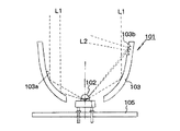
即ち、図3は従来の車両用信号灯要部の側断面図であり、図示の車両用信号灯101は、光源であるLED(発光ダイオード)102と、このLED102から出射する光を反射させる椀状のリフレクタ103を備えている。ここで、リフフレクタ103は、LED102の付近に焦点を有する放物面系の反射面103aを備えており、その反射面103aの一部にはプリズム状の側方用カット103bが形成されている。尚、LED102はLED基板105上に実装されている。
That is, FIG. 3 is a side sectional view of a main part of a conventional vehicle signal lamp. The illustrated
斯かる車両用信号灯101において、LED102が起動されてこれが発光すると、大部分の光L1は、リフレクタ103の反射面103aで反射してメイン配光(平行光)として図3の上方へ向かい、一部の光L2は、側方用カット103bで反射して光軸に対して側方に80°方向の光(80°方向配光)として車両の外側方に向かう。
In such a
しかしながら、図3に示す従来の車両用信号灯101において、リフレクタ103の成形時にその反射面103aの一部にプリズム状の側方用カット103bを形成するには、スライド型が別途必要となるために型構造が複雑化し、製造コストが高くなるという問題がある。
However, in the conventional
本発明は上記観点に鑑みてなされたもので、その目的とする処は、低コストで簡単に製造されて所望の側方配光特性を満足することができる車両用信号灯を提供することにある。 The present invention has been made in view of the above viewpoints, and an object thereof is to provide a vehicular signal lamp that can be easily manufactured at low cost and can satisfy desired side light distribution characteristics. .
上記目的を達成するため、請求項1記載の発明は、光源と、該光源からの光を反射させるリフレクタを備える車両用信号灯において、前記リフレクタを透明な導光体から成る成形体で椀状に構成し、前記リフレクタには、前記光源が配置される孔と、該孔と異なる位置に設けた開口部が形成され、前記孔の端面は、前記光源に対向し、前記開口部の周縁の一部には、外側方に向かって広がる斜面状の反射面が形成されており、前記開口部の周縁の反射面は、前記光源からの放射光の一部が前記リフレクタで反射した後に前記開口部を通過して到達する位置で、且つ、前記リフレクタを成形する際にアンダーカットとならない位置に形成されており、前記光源からの放射光のうちの一部は、前記開口部の周縁の反射面にて反射した光が、車両の外側方に向かい、前記光源からの放射光のうちの一部は、前記孔の端面から入射して前記リフレクタの他端面から出射することを特徴とする。
In order to achieve the above object, according to a first aspect of the present invention, there is provided a vehicular signal lamp including a light source and a reflector that reflects light from the light source. The reflector is formed into a bowl shape with a molded body made of a transparent light guide. The reflector is provided with a hole in which the light source is disposed and an opening provided at a position different from the hole, and an end surface of the hole is opposed to the light source and is a part of a periphery of the opening. The part is formed with a slope-like reflecting surface that spreads outward, and the reflecting surface at the periphery of the opening is formed by reflecting the part of the radiated light from the light source after the reflector reflects the opening. Is formed at a position that does not cause an undercut when the reflector is formed, and a part of the emitted light from the light source is a reflection surface at the periphery of the opening. The light reflected by the Toward the side, a part of the light emitted from the light source is characterized by emitting incident from an end face of the hole from the other end face of the reflector.
請求項2記載の発明は、請求項1記載の発明において、前記基板が前記リフレクタの後面側に位置することを特徴とする。
According to a second aspect of the present invention, in the first aspect of the present invention, the substrate is located on a rear surface side of the reflector .
本発明によれば、光源から出射した光のうち、リフレクタの開口部を通過した光は、リフレクタの外面の開口部周縁に形成された反射面で反射して外側方に向かうため、当該車両用信号灯に要求される側方配光特性を満足することができる。そして、開口部が形成されるリフレクタの型成形においては、開口部がアンダーカットとならないために型を一方向に抜くことができる。このため、リフレクタの成形にスライド型が不要となり、型構造が単純化して製造コストが低く抑えられる。
According to the present invention, among the light emitted from the light source, the light that has passed through the opening of the reflector is reflected by the reflecting surface formed on the periphery of the opening on the outer surface of the reflector and travels outward. Side light distribution characteristics required for signal lights can be satisfied. And in the shaping | molding of the reflector in which an opening part is formed, since an opening part does not become an undercut, a type | mold can be extracted in one direction. This eliminates the need for a slide mold for molding the reflector, simplifies the mold structure, and reduces manufacturing costs.
又、リフレクタを透明な導光体で構成するとともに、その端面を除く内外面を反射面としたため、リフレクタの光源に対向する一端面から該リフレクタ内に入射した光は、全反射しながらリフレクタ内を進み、該リフレクタの他端面から出射するため、リフレクタの端部周縁が光り、特徴的な意匠を演出することができる。
In addition, since the reflector is composed of a transparent light guide and the inner and outer surfaces except for the end surfaces are reflecting surfaces, the light incident on the reflector from one end surface facing the light source of the reflector is totally reflected and reflected in the reflector. Since the light is emitted from the other end face of the reflector, the peripheral edge of the reflector shines and a characteristic design can be produced.
以下に本発明の実施の形態を添付図面に基づいて説明する。 Embodiments of the present invention will be described below with reference to the accompanying drawings.
図1は本発明に係る車両用信号灯要部の正面図、図2は図1のA−A線断面図であり、図示の車両用信号灯1は車両後部に配置されるテールランプである。
FIG. 1 is a front view of an essential part of a vehicle signal lamp according to the present invention, FIG. 2 is a cross-sectional view taken along line AA of FIG. 1, and the illustrated
図示の車両用信号灯1は、図2に示すように、光源であるLED2と、このLED2から出射する光を反射させる椀状のリフレクタ3を備えている。ここで、リフレクタ3の中心部には円孔4が形成されており、この円孔4の中心に前記LED2が配置されている。尚、LED2はLED基板5上に実装されている。
As illustrated in FIG. 2, the illustrated
ところで、本実施の形態では、リフレクタ3は透明な導光体で構成されており、その内面はLED2の付近に焦点を有する放物面系の反射面3aを構成しており、この反射面3aにはアルミ蒸着が施されている。そして、このリフレクタ3の一部には、矩形の開口部3Aが形成されており、リフレクタ3の外面の開口部3Aの周縁の一部には、外側方に向かって広がる斜面状の反射面3bが形成されており、この反射面3bを含むリフレクタ3の外面にはアルミ蒸着が施されている。但し、リフレクタ3のLED2に対向する端面3c(円孔4の内周面)と開口端面3dにはアルミ蒸着が施されていない。従って、リフレクタ3の開口部3Aと端面3c,3dを除く内面と外面にはアルミ蒸着が施されており、この部分は全体として反射面を構成している。
By the way, in this Embodiment, the
尚、以上は車両用信号灯1を構成する主要部の構成のみについて説明したが、実際の車両用信号灯1は、ハウジングとその開口部を覆うレンズ(共に不図示)によって画成された灯室内に前記LED2やリフレクタ3を収容して構成されている。
Although only the configuration of the main part constituting the
以上のように構成された車両用信号灯1において、LED2が起動されてこれが発光すると、大部分の光L1は、リフレクタ3の反射面3aで反射してメイン配光(平行光)として図2の上方へ向かい、一部の光L2は、リフレクタ3の反射面3aで反射した後に開口部3Aを通過し、開口部3Aの周縁の一部に形成された反射面3bで反射して光軸に対して側方に80°方向の光(80°方向配光)として車両の外側方に向かい、車両外側方向に80°の領域を所定の光度(例えば、0.05cd)で照明する。
In the
以上のように、本実施の形態では、LED2から出射した光のうち、リフレクタ3の開口部3Aを通過した光L2は、リフレクタ3の外面の開口部3Aの周縁に形成された反射面3bで反射して外側方に向かうため、当該車両用信号灯1に要求される側方配光特性を満足することができる。そして、開口部3Aが形成されるリフレクタ3の型成形においては、開口部3Aがアンダーカットとならないために型を一方向に抜くことができる。このため、リフレクタ3の成形にスライド型が不要となり、型構造が単純化して製造コストが低く抑えられる。
As described above, in the present embodiment, the light L2 that has passed through the
又、本実施の形態では、リフレクタ3を透明な導光体で構成するとともに、その端面3c,3dを除く内外面を反射面としたため、リフレクタ3のLED2に対向する一端面3cから該リフレクタ3内に入射した光L3は、図2に示すように全反射しながらリフレクタ3内を進み、該リフレクタ3の他端面3dから出射するため、リフレクタ3の端部周縁が光り、特徴的な意匠を演出することができるという効果も得られる。
In the present embodiment, the
尚、以上は本発明をテールランプに対して適用した形態について説明したが、本発明は、ストップランプ等の他の任意の車両用信号灯に対しても同様に適用可能であることは勿論である。又,以上の実施の形態では、光源としてLEDを使用した車両用信号灯について説明したが、本発明は、LED以外のバルブ等を光源とする車両用信号灯に対しても同様に適用可能である。 Although the present invention has been described with respect to a form in which the present invention is applied to a tail lamp, it is needless to say that the present invention can be similarly applied to other arbitrary vehicle signal lights such as a stop lamp. In the above embodiment, a vehicle signal lamp using an LED as a light source has been described. However, the present invention is also applicable to a vehicle signal lamp using a bulb or the like other than an LED as a light source.
1 車両用信号灯
2 LED(光源)
3 リフレクタ
3A リフレクタの開口部
3a,3b リフレクタの反射面
3c,3d リフレクタの探検
4 円孔
5 LED基板
L1〜L3 光
1
DESCRIPTION OF
Claims (2)
前記リフレクタを透明な導光体から成る成形体で椀状に構成し、
前記リフレクタには、前記光源が配置される孔と、該孔と異なる位置に設けた開口部が形成され、
前記孔の端面は、前記光源に対向し、
前記開口部の周縁の一部には、外側方に向かって広がる斜面状の反射面が形成されており、
前記開口部の周縁の反射面は、前記光源からの放射光の一部が前記リフレクタで反射した後に前記開口部を通過して到達する位置で、且つ、前記リフレクタを成形する際にアンダーカットとならない位置に形成されており、
前記光源からの放射光のうちの一部は、前記開口部の周縁の反射面にて反射した光が、車両の外側方に向かい、
前記光源からの放射光のうちの一部は、前記孔の端面から入射して前記リフレクタの他端面から出射することを特徴とする車両用信号灯。 In a vehicle signal lamp comprising a light source and a reflector that reflects light from the light source,
The reflector is formed in a bowl shape with a molded body made of a transparent light guide,
The reflector is formed with a hole in which the light source is disposed and an opening provided at a position different from the hole,
The end face of the hole faces the light source,
A part of the periphery of the opening is formed with a sloped reflecting surface that spreads outward.
The reflection surface at the periphery of the opening is a position where a part of the radiated light from the light source is reflected by the reflector and then reaches through the opening, and is undercut when the reflector is molded. It is formed at a position that does not become
A part of the radiated light from the light source is reflected by the reflection surface at the periphery of the opening, and is directed outward of the vehicle.
A part of the radiated light from the light source is incident on the end surface of the hole and is emitted from the other end surface of the reflector .
前記基板が前記リフレクタの後面側に位置することを特徴とする請求項1記載の車両用信号灯。
The light source is an LED mounted on a substrate;
2. The vehicular signal lamp according to claim 1, wherein the substrate is located on a rear surface side of the reflector .
Priority Applications (1)
| Application Number | Priority Date | Filing Date | Title |
|---|---|---|---|
| JP2012266012A JP6054724B2 (en) | 2012-12-05 | 2012-12-05 | Vehicle signal lights |
Applications Claiming Priority (1)
| Application Number | Priority Date | Filing Date | Title |
|---|---|---|---|
| JP2012266012A JP6054724B2 (en) | 2012-12-05 | 2012-12-05 | Vehicle signal lights |
Publications (2)
| Publication Number | Publication Date |
|---|---|
| JP2014112473A JP2014112473A (en) | 2014-06-19 |
| JP6054724B2 true JP6054724B2 (en) | 2016-12-27 |
Family
ID=51169482
Family Applications (1)
| Application Number | Title | Priority Date | Filing Date |
|---|---|---|---|
| JP2012266012A Active JP6054724B2 (en) | 2012-12-05 | 2012-12-05 | Vehicle signal lights |
Country Status (1)
| Country | Link |
|---|---|
| JP (1) | JP6054724B2 (en) |
Families Citing this family (2)
| Publication number | Priority date | Publication date | Assignee | Title |
|---|---|---|---|---|
| JP7139200B2 (en) * | 2018-09-03 | 2022-09-20 | スタンレー電気株式会社 | vehicle lamp |
| FR3085638A1 (en) * | 2018-09-07 | 2020-03-13 | Psa Automobiles Sa | LIGHTING DEVICE WITH SINGLE PHOTON SOURCE PROVIDING TWO DIFFERENT PHOTOMETRIC FUNCTIONS |
Family Cites Families (2)
| Publication number | Priority date | Publication date | Assignee | Title |
|---|---|---|---|---|
| JPS583202Y2 (en) * | 1978-03-02 | 1983-01-20 | サンデン株式会社 | bicycle headlight |
| JP3195294B2 (en) * | 1998-08-27 | 2001-08-06 | スタンレー電気株式会社 | Vehicle lighting |
-
2012
- 2012-12-05 JP JP2012266012A patent/JP6054724B2/en active Active
Also Published As
| Publication number | Publication date |
|---|---|
| JP2014112473A (en) | 2014-06-19 |
Similar Documents
| Publication | Publication Date | Title |
|---|---|---|
| EP2990720B1 (en) | Vehicle lighting unit | |
| JP5363235B2 (en) | Vehicle lighting | |
| JP5677122B2 (en) | Vehicle lighting | |
| JP7081977B2 (en) | Vehicle lighting | |
| JP2012064533A (en) | Lamp fitting for vehicle | |
| JP6975587B2 (en) | Vehicle lighting | |
| JP2016225254A (en) | Vehicular lighting fixture | |
| JP2016054081A (en) | Transparent material and lighting fixture | |
| JP5255947B2 (en) | Vehicle lamp | |
| JP6597024B2 (en) | Vehicle lighting | |
| JP2015153577A (en) | vehicle lamp | |
| JP2016046114A (en) | Vehicle lighting | |
| JP2015088375A (en) | Light fixture | |
| JP2015162362A (en) | Vehicle lighting | |
| JP2018120658A (en) | Vehicle lighting | |
| JP2015008111A (en) | Composite lamp unit using linear light guide body, and vehicular lighting device | |
| JP6205793B2 (en) | Vehicle lighting | |
| CN203010497U (en) | Integrated Radial Lamp Lens | |
| JP2014164975A (en) | Vehicle lighting appliance | |
| JP5563210B2 (en) | Lamp | |
| JP2014112473A (en) | Vehicular signal lamp | |
| JP6221438B2 (en) | Vehicle lighting | |
| JP2019204595A (en) | Vehicular lighting fixture | |
| JP5363179B2 (en) | Vehicle lighting | |
| JP2011175822A (en) | Light guide lens and vehicular headlight |
Legal Events
| Date | Code | Title | Description |
|---|---|---|---|
| A621 | Written request for application examination |
Free format text: JAPANESE INTERMEDIATE CODE: A621 Effective date: 20151118 |
|
| A131 | Notification of reasons for refusal |
Free format text: JAPANESE INTERMEDIATE CODE: A131 Effective date: 20160831 |
|
| A977 | Report on retrieval |
Free format text: JAPANESE INTERMEDIATE CODE: A971007 Effective date: 20160831 |
|
| A521 | Request for written amendment filed |
Free format text: JAPANESE INTERMEDIATE CODE: A523 Effective date: 20161021 |
|
| TRDD | Decision of grant or rejection written | ||
| A01 | Written decision to grant a patent or to grant a registration (utility model) |
Free format text: JAPANESE INTERMEDIATE CODE: A01 Effective date: 20161116 |
|
| A61 | First payment of annual fees (during grant procedure) |
Free format text: JAPANESE INTERMEDIATE CODE: A61 Effective date: 20161201 |
|
| R150 | Certificate of patent or registration of utility model |
Ref document number: 6054724 Country of ref document: JP Free format text: JAPANESE INTERMEDIATE CODE: R150 |
|
| R250 | Receipt of annual fees |
Free format text: JAPANESE INTERMEDIATE CODE: R250 |
|
| R250 | Receipt of annual fees |
Free format text: JAPANESE INTERMEDIATE CODE: R250 |
|
| R250 | Receipt of annual fees |
Free format text: JAPANESE INTERMEDIATE CODE: R250 |
|
| R250 | Receipt of annual fees |
Free format text: JAPANESE INTERMEDIATE CODE: R250 |
|
| R250 | Receipt of annual fees |
Free format text: JAPANESE INTERMEDIATE CODE: R250 |
|
| R250 | Receipt of annual fees |
Free format text: JAPANESE INTERMEDIATE CODE: R250 |