EP1021943A2 - Landwirtschaftliche Verteilmaschine - Google Patents
Landwirtschaftliche Verteilmaschine Download PDFInfo
- Publication number
- EP1021943A2 EP1021943A2 EP00101127A EP00101127A EP1021943A2 EP 1021943 A2 EP1021943 A2 EP 1021943A2 EP 00101127 A EP00101127 A EP 00101127A EP 00101127 A EP00101127 A EP 00101127A EP 1021943 A2 EP1021943 A2 EP 1021943A2
- Authority
- EP
- European Patent Office
- Prior art keywords
- frame
- distributor according
- wheels
- drawbar
- impellers
- Prior art date
- Legal status (The legal status is an assumption and is not a legal conclusion. Google has not performed a legal analysis and makes no representation as to the accuracy of the status listed.)
- Granted
Links
Images











Classifications
-
- A—HUMAN NECESSITIES
- A01—AGRICULTURE; FORESTRY; ANIMAL HUSBANDRY; HUNTING; TRAPPING; FISHING
- A01B—SOIL WORKING IN AGRICULTURE OR FORESTRY; PARTS, DETAILS, OR ACCESSORIES OF AGRICULTURAL MACHINES OR IMPLEMENTS, IN GENERAL
- A01B59/00—Devices specially adapted for connection between animals or tractors and agricultural machines or implements
- A01B59/04—Devices specially adapted for connection between animals or tractors and agricultural machines or implements for machines pulled or pushed by a tractor
- A01B59/042—Devices specially adapted for connection between animals or tractors and agricultural machines or implements for machines pulled or pushed by a tractor having pulling means arranged on the rear part of the tractor
-
- A—HUMAN NECESSITIES
- A01—AGRICULTURE; FORESTRY; ANIMAL HUSBANDRY; HUNTING; TRAPPING; FISHING
- A01B—SOIL WORKING IN AGRICULTURE OR FORESTRY; PARTS, DETAILS, OR ACCESSORIES OF AGRICULTURAL MACHINES OR IMPLEMENTS, IN GENERAL
- A01B51/00—Undercarriages specially adapted for mounting on various kinds of agricultural tools or apparatus
- A01B51/04—Undercarriages specially adapted for mounting on various kinds of agricultural tools or apparatus drawn by animal or tractor
-
- A—HUMAN NECESSITIES
- A01—AGRICULTURE; FORESTRY; ANIMAL HUSBANDRY; HUNTING; TRAPPING; FISHING
- A01C—PLANTING; SOWING; FERTILISING
- A01C7/00—Sowing
- A01C7/20—Parts of seeders for conducting and depositing seed
- A01C7/208—Chassis; Coupling means to a tractor or the like; Lifting means; Side markers
Definitions
- the invention relates to an agricultural distributor according to the The preamble of claim 1.
- the invention has for its object to provide a distributor which the overall center of gravity for the transport journey can be relatively low.
- each drive with a swing arm over a hinge is articulated on the frame in an upright plane.
- This will created the prerequisite for that between each swing arm and the frame acting hydraulic cylinder to the position of the wheels Frame or to the tank can be adjusted depending on the conditions of use. For example, by lowering the wheels during work compared to the frame the frame with the structural elements, such as Tank be raised, so that there is a large ground clearance for the ordering work results.
- the frame with the Construction elements through the relative adjustment of the wings with the wheels be lowered relative to the frame, so that there is an advantageous low Overall center of gravity of the sprayer results.
- the wings in this way are mounted on the frame that for adjusting the track width of the wheels Suspension the wings can be moved transversely to the direction of travel and in different positions are arranged lockable.
- each hydraulic cylinder has a shut-off element, For example, a shut-off valve or a shut-off valve is assigned.
- a shut-off valve or a shut-off valve is assigned.
- the Storage tank is designed such that it extends laterally above the Wheels located. It can also be advantageous if the storage container has a has a trapezoidal cross-section, with the narrow area in the lower Area.
- chassis is achieved in that at least some of the wheels are steerably arranged on the frame.
- the front and / or rear wheels with different Gauges are adjustable to each other.
- the wheels are around 30-60 cm the bottom to the top position and vice versa, preferably stepless, are adjustable.
- the supports are so designed that in connection with the actuators the wheels can be lifted off the ground. This is an easy wheel change or a track width adjustment or change possible in a simple manner.
- the adjustment elements can be used as double-acting hydraulic cylinders or as single-acting hydraulic cylinders with associated springs.
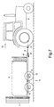
- the distribution machine designed as a trailed agricultural sprayer 1 has the frame 1 on the front of this frame 1 is the Drawbar 2 arranged, while on the back of the frame 1 Distributor linkage 3 is located.
- the drawbar 2 is 4 at its front end via a coupling device 5 to the lower link 6 of the three-point linkage 7 of the Agricultural tractor 8 coupled.
- the storage tank 9 is on the frame 1 arranged. In the exemplary embodiment, the storage tank 9 points in the direction of travel 10 seen a trapezoidal cross-section, with the narrower side in lower area.
- the width of the storage tank 9 is in the upper area about 2.50 m.
- the field sprayer is equipped with a so-called tandem chassis 11.
- Each Impeller 12 of the tandem chassis 11 is by means of a rocker 13 via a joint 14 arranged on the frame 1 in an upright plane.
- the wings 13 are over the Joints 14 fastened to the frame 1 by means of a sliding guide 15.
- the hydraulic cylinders 14 are connected to the hydraulic system of the tractor or to one On-board hydraulic system of the field sprayer connected. In the to that Hydraulic cylinder 14 leading lines are gas bubbles, not shown arranged. An integrated spring system is thus achieved. Furthermore are each hydraulic cylinder 14 an Abaperrelement, not shown, For example, a shut-off valve or a shut-off valve is assigned.
- About these slidable Elements 16 and 17 can be the track width of the wheels 12 of the tandem chassis 10 can be set.
- the Sliding guide 15 can be assigned a hydraulic cylinder, not shown, by means of which the two parts 16 and 17 can be adjusted to each other. So is the track width is easily adjustable, for example from the tractor seat.
- the shut-off elements assigned to the hydraulic cylinders 14 or the hydraulic lines can be adjusted by hand or via remote control devices from the tractor seat. As a result, different settings of the rockers 13 with the wheels 12 to each other are possible. A simple wheel change of the wheels can also be carried out in this way. For this purpose, the shut-off elements only have to be brought into the corresponding position so that the wheel to be changed is lifted out. A simple track width adjustment is possible in the same way. So it's a Jack "integrated into the tandem chassis.
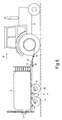
- the wings 13 with the wheels 12 over the hydraulic cylinders 14 brought into the position shown in Fig.1.
- the drawbar 2 is accordingly in the Height position set so that a horizontal position, as shown in Fig.1, which is parallel to the surface of the floor.
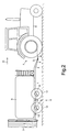
- the field sprayer will achieve a relatively low center of gravity of the sprayer set according to Fig. 2.
- the frame 1 is through the swiveling of the wheels 12 with the rockers 13 over the Hydraulic cylinder 14 lowered so that it is as low as possible Total center of gravity for the field sprayer results.
- the lower links are also 6 of the three-point linkage 7 of the tractor 8 lowered, so that the front Field sprayer is lowered. Furthermore, the distributor linkage 3, which is located on the back of the sprayer, in the folded position bring to. Due to this lowering of the field sprayer, there is therefore a advantageous low center of gravity. Due to the low center of gravity Fig. 1, the risk of tipping is significantly reduced. Furthermore, the view over the Field sprayer good backwards, which is important in road traffic.
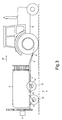
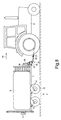
- FIG 3 shows a further mode of operation of the field sprayer Distributor. Only the front wheels 12 are used for turning at the end of the field of the tandem chassis 11 raised, so that a better turning behavior is achievable.
- the track width by appropriate Position of the shut-off elements, the respective impeller 12 in a targeted manner to raise this to the direction 10 to the required position bring so that the desired track width is adjustable.
- An adjustment or a raising and lowering of the chassis 11 is between 30 and 60 cm possible.
- front impeller 12 have a larger diameter than the rear impeller.
- relatively large wheels 12 can be provided, so that some when lifting the wheels 12 of the tandem chassis 11 can assume the supporting function, without sinking too deeply into the ground.
- the shut-off elements in the to the hydraulic cylinders 14 are assigned to the rocker 13, it is possible to only some of the hydraulic cylinders 14 to operate.
- the wheels 12 on one side regardless of the wheels 12 raised or lowered on the other side become.
- This is advantageous when driving across a slope, for example hereby only the wheels 12 are adjusted on one side, so one horizontal position or at least approximately horizontal position of the field sprayer to reach. This results in a center even when driving across the slope lying center of gravity, so the risk of tipping when driving across the slope is considerable reduced.
- the hydraulic cylinder 14 the are assigned to individual wheels 12, can be adjusted in this way by means of suitable means or be resilient that the front and / or rear wheels 12 completely or partially pulled up or down so that the weight balance between the rear and front wheels 12 according to the Operating conditions can be set.
- the field sprayer according to Figures 6 and 7 differs from the field sprayer 1 to 5 in that the articulated drawbar 18th is arranged.
- the articulated drawbar 18 is connected to the frame by means of a joint 19 1 movably arranged in an upright plane.
- a hydraulic cylinder 20 is adjustable, in which the position of the Articulated drawbar 18 can be adjusted to frame 1.
- a sprayer with one Articulated drawbar 18 is used in particular when the drawbar 18 is not via a coupling device to the lower link of the three-point linkage is coupled, but on the drawbar or the muzzle of the Agricultural tractor is attached.
- About the articulated drawbar 21 can then Height of the front area of the sprayer can be set, which at the embodiment of FIGS. 1 to 5 by the height adjustment Lower link 6 of the three-point linkage 7 happens.
- the distribution machine designed as a field sprayer according to FIGS. 8 and 9 differs 6 and 7 by a different design of the arranged on the front of the frame 1 articulated drawbar 31.
- This type the articulated drawbar 31 has the drawbar element 32 which can be raised and lowered, which by means of the parallelogram handlebars 33 and 34 on the column element 35 on the Frame 1 is articulated.
- One of the parallelogram links is the hydraulic cylinder 36 for lifting and lowering the drawbar element 32 relative to the Assigned to frame 1.
- the operation of the articulated drawbar 31 corresponds to that of the articulated drawbar 21 6 and 7, so that the field sprayer according to FIGS. 8 and 9 in the transport position 8 and the operating position according to FIG. 9 and intermediate positions can be brought.
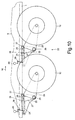
- 10 to 12 show a further embodiment of a tandem chassis 22 of the as a field sprayer distributor.
- the swing arm 23 and the Hydraulic cylinder 24, which is assigned to the rocker 23, are on one common component 25 arranged and together transverse to the direction of travel 10 slidable to set different track widths of the wheels 12.
- the Swing arm 23 is articulated on the strut 27 of the component 25 via the joint 26.
- This strut 27 is on a square tube 28, which is an inner guide element forms a sliding guide 29, attached.
- This inner guide member 28 of the Sliding guide 29 is formed in a square tube 30 External guide element of the sliding guide 29 transverse to the direction of travel 10 slidably arranged.
- the outer guide element 30 is on the frame 1 of the Field sprayer attached.
- the strut 27 is extended to the front, so that on the front end of this extension element of the strut 27 of the hydraulic cylinder 24, which engages the rocker 23, is articulated.
- the hydraulic cylinders 24 are not shown shut-off elements, such as shut-off valves or Assigned valve elements. These shut-off elements can be operated manually or remotely be so that on the hydraulic system of the tractor or an onboard Hydraulic system of the field sprayer, the hydraulic cylinders 24 separately or together can be operated.
- the hydraulic system formed such that the assigned to the individual wheels 12 Hydraulic cylinder 24 for lifting and lowering the rockers 23 in such a way can be actuated that the front and / or rear of the wheels 12 opposite assume a different or the same position in each of the other wheels 12 can. It is of course also possible to close the wheels 12 together swivel to bring the sprayer into the appropriate position, i.e. that it can be raised relative to the frame 1 to the Lower the overall center of gravity for the transport journey or the wheels with the Swing 23 against the frame 1 can be adjusted so that the Field sprayer for use especially in higher grown crops is raised in order to achieve sufficient ground clearance, as is the case with 1 to 7 is described.
- hydraulic cylinders 24 can be adjusted in this way by means of suitable means and / or resilient so that the front and / or rear wheels 12 completely or can be partially pulled up or pushed down so that the Weight balance between the rear and front wheels 12 is adjustable according to the conditions of use.
- the rockers 23 are the stops 37 and that determine an end position the other end position determining and designed as a rubber buffer resilient Associated stops 38 which determine the end position of the rocker 23. Furthermore, in the lines leading to the hydraulic cylinders 24 are 39 Gas bubbles 40 trained compensation and spring elements arranged. In the Operating position, the strut 23 is supported on the strut element 23 ' resilient stop 38, while in the operating position the gas bubbles 40th each serve as a spring element.
- the impellers 12 on each side are at a suitable height by suitable means to each other and / or to the frame 1 separately and differently adjustable so that it can be used in a wide variety of situations and terrain the optimal position of the sprayer is always adjustable.
- the track width of the impellers 12 can be adjusted by means of this hydraulic cylinder easy and simple to set.
- those assigned to the sliding guide Hydraulic cylinder with the hydraulic cylinders assigned to the swingarm are connected in such a way that when lowering the frame 1 the sprayer reduces the track width and when lifting the frame 1 the Field sprayer the track gauge is enlarged.
- the stub axles for the arrangement of the wheels 12 on the wings are as standardized stub axles designed to facilitate easy replacement guarantee.
- the wheels 12 can be arranged on the frame 1 in a steerable manner. It is also possible to use the rear wheels 12 as pendulum wheels to be arranged in order to automatically achieve an optimum, especially when cornering To ensure caster of the wheels 12.
- the lowering of the frame 1 by pivoting the wings with the Wheels 12 can also be used when swap bodies on the Frame 1 can be arranged, the different construction system slightly opposite to be able to replace.
- the frame After unlocking the body system elements from Frame, the frame can be lowered and the body system elements are placed on storage elements attached to them.
- the frame 1 with chassis 1 and drawbar 2 After lowering of the frame, the frame 1 with chassis 1 and drawbar 2 can be moved away become. In reverse order, others can be easily created Arrange assembly system elements on the frame.
- the self-propelled distributor shown in FIG. 11 is a field sprayer educated.
- the self-propelled vehicle has the frame 40, which extends over the rear Tandem chassis 41 and the front steering gear 42 is supported on the floor. in the The front area of the frame 40 is the driver's cabin 43.
- the self-propelled vehicle is equipped with a so-called tandem chassis 41.
- the Drive of the axes of the tandem chassis 41 is not shown.
- the axes are from a conventional and well-known drive train Drive motor driven.
- the swing arm 23 and the hydraulic cylinder 24, which is assigned to the swing arm 23, are arranged on a common component 25 and together across Direction of travel 10 displaceable by different track widths of the wheels 12 adjust.
- the rocker 23 is via the joint 26 on the strut 27 of the Component 25 articulated.
- This strut 27 is on a square tube 28, which a Inner guide element of a sliding guide 29 forms, attached.
- This inner Guide element of the sliding guide 29 is formed in a square tube External guide element of the sliding guide 29 transverse to the direction of travel 10 slidably arranged.
- the outer guide element is on the frame 1 Field sprayer attached.
- the strut 27 is extended to the front, so that on the front end of this extension element of the strut 27 of the hydraulic cylinder 24, which engages the rocker 23, is articulated.
- the hydraulic cylinders 24 are not shown shut-off elements, such as shut-off valves or Assigned valve elements. These shut-off elements can be operated manually or remotely be so that on the hydraulic system of the tractor or an onboard Hydraulic system of the field sprayer, the hydraulic cylinders 24 separately or together can be operated.
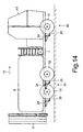
- the hydraulic system formed such that the assigned to the individual wheels 12 Hydraulic cylinder 24 for lifting and lowering the rockers 23 in such a way can be actuated that the front and / or rear of the wheels 12 opposite assume a different or the same position in each of the other wheels 12 can. It is of course also possible to close the wheels 12 together swivel to bring the sprayer into the appropriate position, i.e. that it can be raised relative to the frame 40 to the Lower the overall center of gravity for the transport journey, as shown in Fig. 14, or the wheels 12 with the rockers 23 opposite the frame 40 be adjusted below so that the sprayer can be used especially in higher grown cultures is raised to provide adequate ground clearance, as shown in Fig. 13, how to achieve this with respect to Figs. 1 to 12 is described.
- hydraulic cylinders 24 can be adjusted in this way by means of suitable means and / or resilient so that the front and / or rear wheels 12 completely or can be partially pulled up or pushed down so that the Weight balance between the rear and front wheels 12 is adjustable according to the conditions of use.
- the rockers 23 are assigned, not shown, resilient stops, which determine the end position of the wings 23. Furthermore are in the hydraulic cylinders 24 leading lines as gas bubble 40 trained compensation and Spring elements arranged.
- the impellers 12 on each side are at a suitable height by suitable means to each other and / or to the frame 1 separately and differently adjustable so that it can be used in a wide variety of situations and terrain the optimal position of the sprayer is always adjustable.
- the track width of the impellers 12 can be adjusted by means of this hydraulic cylinder easy and simple to set.
- those assigned to the sliding guide Hydraulic cylinder with the hydraulic cylinders assigned to the swingarm are connected in such a way that when lowering the frame 1 the sprayer reduces the track width and when lifting the frame 1 the Field sprayer the track gauge is enlarged.
- the lowering of the frame 40 by pivoting the wings with the Wheels 12 can also be used when swap bodies on the Frame 40 can be arranged, the different construction system easily opposite to be able to replace.
- the frame After unlocking the body system elements from Frame, the frame can be lowered and the body system elements are placed on storage elements attached to them.
- the frame After lowering of the frame can be the frame 40 with chassis 41 and 42. In reverse Sequence can be easily built on the other body system elements Arrange frame 40.
- the front tandem impeller is raised. This is preferred for turning at the end of the field or for transport on the Road made when the storage tank 9 is empty.
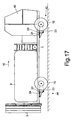
- FIGS. 16 and 17 differs from that Embodiment according to Figures 12 to 15 in that the rear chassis 44th is not designed as a tandem chassis 41 but as a single wheel chassis 44.
- the Suspension of the wings 23 on the frame 40 corresponds to the suspension of the Swing 23 according to FIGS. 12 to 15.
- the distribution machine designed as a trailed agricultural sprayer 18 has the frame 1. On the front of this frame is 1 the drawbar 2 arranged, while on the back of the frame 1 Distributor linkage 3 is located. The drawbar 2 is 4 at its front end via a coupling device 5 to the lower link 6 of the three-point linkage 7 of the Agricultural tractor 8 coupled.
- the storage tank 9 is on the frame 1 arranged. In the exemplary embodiment, the storage tank 9 points in the direction of travel 10 seen in the rear area 45 on a trapezoidal cross-section, the narrower side is in the lower area. The width of the storage tank 9 is about 2.50 m in the upper area. The storage tank 9 has in the front area also a large width in the lower area. In other words: The lower rear area 45 is drawn in in the area of the impellers.
- the field sprayer is equipped with chassis 11 '.
- Each wheel 12 of the chassis 11 ' is upright by means of a rocker 13 via a joint 14 on the frame 1 Level arranged.
- the rockers 13 are via the joints 14 by means of a Sliding guide 15 attached to the frame 1.
- the hydraulic cylinders 14 are connected to the hydraulic system of the tractor or to one On-board hydraulic system of the field sprayer connected. In the to that Hydraulic cylinder 14 leading lines are gas bias, not shown arranged. An integrated spring system is thus achieved. Furthermore each hydraulic cylinder 14 is a shut-off element, not shown, For example, a shut-off valve or a shut-off valve is assigned.
- the sliding guide 15, with which the wheels 12 are arranged on the frame 1 are an external guide element designed as a square tube Sliding guide 15 on.
- this square tube is another square tube as Inner guide element slidably guided on the outside by means of Joint 15 the rocker 13 is articulated.
- the sliding guide 15 a hydraulic cylinder, not shown, can be assigned, by means of which the both parts 16 and 17 can be adjusted to each other. So the gauge is easily adjustable, for example from the tractor seat.
- the two height-adjustable supports 46 are spaced apart. In order to lift the wheels 12 to change the wheel or the wheels 12 to adjust the track width, the supports 46 are brought into the position shown by broken lines 46 'and locked. The distributor is then lifted in the front area via the lower link 6 of the three-point linkage of the tractor. Because the machine is supported in the lower area on the supports 46 ', the wheels 12 come free from the ground. So it's kind of a Jack "integrated into the machine.
- the wings 13 with the wheels 12 over the hydraulic cylinders 14 brought into the position shown in Fig.1.
- the drawbar 2 is accordingly in the Height position set so that a horizontal position, as shown in Fig.1, which is parallel to the surface of the floor.
- the field sprayer will achieve a relatively low center of gravity of the sprayer lowered, as described in Fig.2.
- the distribution machine according to Fig. 19 differs from the distribution machine 1 by the other articulation of the rocker 13 and the Hydraulic cylinder 15.
- the rockers 13 articulated at the front, that is to say arranged in a pulling manner, while in FIG. 1 are arranged in the rear area, i.e. pushing.
- the Storage container 9 retracted in the rear area 45, as shown in Fig.20, while he in the front area is also almost as wide in the lower area, like in the upper area.
- FIGS. 18 and 19 show a storage container, which, in the rear lower region 45, explained with reference to FIGS. 18 and 19, for swiveling the impellers upward has moved in, while it is almost as wide in the lower front area as in upper area is formed.
- FIG. 21 shows the arrangement of a rocker 23 on an adjustable common component 46.
- the swing arm 23 of the chassis and the Hydraulic cylinder 47, which is assigned to the rocker 23, are on one arranged common component 46 and together transverse to the direction of travel 10 slidable to set different track widths of the wheels 12 can.
- the rocker 23 is on the strut 49 of the component 46 via the joint 48 articulated.
- This strut 49 is on a square tube 28, which a Forms inner guide element of a sliding guide, attached.
- This inner Guide element 28 of the sliding guide is formed in a square tube External guide element, which is attached to the frame, the sliding guide across slidably arranged to the direction of travel.
- the strut 49 is extended to the front.
- the rocker 23 is by means of the joint 48 arranged.
- the swivel lever 50 is in the front area of the strut 49 arranged, on which the hydraulic cylinder 47 engages with one end the rocker 23 on which the impeller 12 is attached engages.
- the swivel lever 50 is supported on the strut 49 via the spring 51.
- the Hydraulic line 52 which leads to the hydraulic cylinder 47, a gas bubble 53 arranged.
- the tension spring 54 anode the rocker 23 pulls up against the single-acting hydraulic cylinder 47.
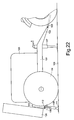
- the towed agricultural spreading machine according to FIG. 22 has the frame 101, which has a drawbar 102 on its front that over suitable coupling elements on the lower links 103 of the three-point linkage are connected.
- the frame 101 continues to be based on the frame 101 rotatably arranged impellers 104.
- this is as Field sprayer trained distributor, a storage tank 105 arranged as well on the back is a folded in by means of elements not shown Position shown distributor boom 106 arranged.
- a parking support 107 in front area of the frame 101 in the transition between frame 101 and Drawbar 102 arranged a parking support 107.
- the two height-adjustable supports 108 are spaced apart from one another arranged.
- the lower link is used 103 of the three-point linkage, the drawbar 102 and thus the entire machine raised.
- the machine is based on the rear Parking supports 108, so that the wheels 104 come off the ground, as Fig.23 shows. Now the wheels 104 can be easily removed, changed, turned over etc. It is also possible to set other track gauges in which the Impellers 104, if the axle is designed accordingly, laterally can be moved to a corresponding track width in a simple manner to be able to adjust.
- the machine When the track width is adjusted or the wheels 104 are reattached, the machine is lowered via the three-point linkage so that the wheels 104 get up again on the floor 109. Then after removing the locking bolt 112 up the parking supports 108 in the in Fig.22 dash-dotted lines drawn position 108 'pushed.
- the distribution machine according to FIG. 24 has the wheels 104, the frame 101 and the drawbar 113, which is equipped with a towing eye 114 and with a hitch 115 of the tractor 116 can be connected.
- the hydraulic cylinders 118 are via hydraulic lines 119 to the hydraulic system of the tractor connected. As shown in Fig. 24, the two hydraulic cylinders 118 are down extended so that the wheels 104 are lifted off the floor 109.
- Track width or the wheels 104 are changed or arranged accordingly, is by switching the hydraulic system to return flow through the return springs 120 the hydraulic cylinders 118 upwards into those with dash-dotted lines drawn position 118 'drawn. It is also possible to use the hydraulic cylinder 118 as a double-acting hydraulic cylinder.
- a frame 101 with running wheels 104 and drawbar 113 are provided, which with the towing eye 114 to the hitch 115 an agricultural tractor 116 is connected.
- the height-adjustable supports 121 are provided at the back of frame 101 by means of the swivel arms 122 over the Swivel joint 123 arranged on the frame 101.
- the hydraulic cylinders 124 are each arranged by means of the swivel arms 122 which the swivel arms 122 are pivotable with the parking support 121.
- the Hydraulic cylinder 124 is connected to the hydraulic system of the hydraulic system Tug 116 connected. In the position shown in Fig.
- the Swivel arms 122 are the Swivel arms 122 lowered with the parking support 121 so that the wheels 104th are lifted off the floor 109.
- the swivel arms 122 are also moved via the hydraulic cylinders 124 the parking supports 121 upwards into those indicated by dash-dotted lines Position 121 'pivoted.
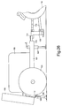
- the distributor according to FIG. 26 has the frame 101 with the drawbar 113 and the towing eye 114 on the towing jaw of the tractor 116 in operation is connected.
- the chassis is in the rear area of the distributor arranged with the two wheels 104.
- On the frame 101 is the as Field sprayer trained distributor of the storage tank 105 is arranged.
- At the Back of the frame 101 is the in via connecting means, not shown Distributed linkage 106 shown folded position.
- the two height-adjustable supports 108 at the rear of the frame 101 arranged.
- the height adjustable supports 108 are in on the frame 101 arranged sleeves 110 out.
- the locking bolt 112 are the The sleeve 110 and the support 108 can be locked to one another in different positions.
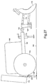
- the Three-point linkage 125 provided coupling frame 126 which, like Fig. 26 shows the drawbar 114 of the drawbar 113 can be connected.
- the Three-point linkage 115 is in connection with the lifting frame 126 Distributor, as Fig.27 shows, in the front area so that the Distributor is supported on the parking supports 108 so that the wheels 104th clear the floor 109 to be able to set a different track width or to change the wheels 104.
- the distributor After setting the track width or Arrangement of the impellers is the distributor by lowering the Three-point linkage 115 lowered again, so that the wheels 104 on again stand up from the floor 109.
- the supports 108 are then removed of the locking bolt in the dash-dotted position 108 '.
Landscapes
- Life Sciences & Earth Sciences (AREA)
- Soil Sciences (AREA)
- Environmental Sciences (AREA)
- Zoology (AREA)
- Engineering & Computer Science (AREA)
- Mechanical Engineering (AREA)
- Catching Or Destruction (AREA)
- Fertilizing (AREA)
Abstract
Description
- Fig.1
- ein als landwirtschaftliche Anhängefeldspritze ausgebildete Verteilmaschine in Seitenansicht und in Prinzipdarstellung und in Arbeitsstellung,
- Fig.2
- die Verteilmaschine in Seitenansicht, in Transportstellung und in Prinzipdarstellung,
- Fig.3
- eine andere Betriebsweise der Verteilmaschine in Prinzipdarstellung,
- Fig.4
- das Tandemfahrwerk der Verteilmaschine in vergrößertem Maßstab, in Seitenansicht und in Prinzipdarstellung,
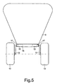
- Fig.5
- das Fahrwerk der Verteilmaschine in der Ansicht von hinten und in Prinzipdarstellung,
- Fig.6
- eine weitere Verteilmaschine in Seitenansicht, in Betriebsstellung und in Prinzipdarstellung,
- Fig.7
- die Verteilmaschine gemäß Fig.6 in Transportstellung, in Seitenansicht und in Prinzipdarstellung,
- Fig. 8
- eine weitere als Feldspritze ausgebildete Verteilmaschine in Seitenansicht, in Betriebsstellung und inTransportstellung,
- Fig. 9
- das Verteilmaschine gemäß Fig. 8 in Betriebstellung,
- Fig.10
- ein weiteres Tandemfahrwerk einer Verteilmaschine in Seitenansicht und in Prinzipdarstellung und
- Fig. 11
- die Aufhängung eines der Laufräder des Tandemfahrwerkes gemäß Fig. 10 im vergrößertem Maßstab und in Teilansicht.
- Fig.12
- das Tandemfahrwerk gemäß Fig.10 in Rückansicht.
- Fig.13
- eine als landwirtschaftlicher Selbstfahrer ausgebildete Verteilmaschine, in Seitenansicht und in Prinzipdarstellung und in Arbeitsstellung,
- Fig.14
- die Verteilmaschine in Seitenansicht, in Transportatellung und in Prinzipdarstellung,
- Fig.15
- eine andere Betriebsweise der Verteilmaschine in Seitenansicht und in Prinzipdarstellung,
- Fig.16
- ein weiterer landwirtschaftlicher Selbstfahrer in Seitenansicht, in Prinzipdarstellung und in Arbeitsstellung,
- Fig.17
- die Verteilmaschine gemäß Fig.16 in Transportstellung und in Prinzipdarstellung,
- Fig.18
- eine weitere als Feldspritze ausgebildete Verteilmaschine in Seitenansicht und in Prinzipdarstellung,
- Fig.19
- eine weitere Verteilmaschine in Seitenansicht und in Prinzipdarstellung,
- Fig.20
- die Verteilmaschine in der Ansicht von hinten,
- Fig.21
- die Aufhängung eines der Laufräder des Fahrwerkes in vergrößertem Maßstab, in Teilansicht und in Seitenansicht,
- Fig.22
- eine gezogene landwirtschaftliche Verteilmaschine in Seitenansicht,
- Fig.23
- die Verteilmaschine gemäß Fig.22, jedoch mit vom Boden abgehobenen Laufrädern,
- Fig.24
- eine weitere Verteilmaschine mit vom Boden abgehobenen Laufrädern,
- Fig.25
- eine weitere Verteilmaschine mit vom Boden abgehobenen Laufrädern,
- Fig.26
- eine weitere Verteilmaschine in Seitenansicht und
- Fig.27
- die Verteilmaschine gemäß Fig.26, jedoch mit vom Boden abgehobenen Laufrädern.

Claims (37)
- Landwirtschaftliche Verteilmaschine, wie beispielsweise Feldspritze, Großflächendüngerstreuer etc. mit einem Laufräder aufweisenden Fahrwerk, einem Rahmen, auf dem Aufbauelemente, wie beispielsweise zumindest ein Vorratstank angeordnet ist und einer Verteileinrichtung, dadurch gekennzeichnet, daß jedes Laufrad (12) am Rahmen (1) in aufrechter Ebene bewegbar angelenkt ist.
- Verteilmaschine nach Anspruch 1, dadurch gekennzeichnet, daß jedes Laufrad (12) mit einer Schwinge (13, 23) über ein Gelenk (15, 26) am Rahmen (1) angelenkt ist.
- Verteilmaschine nach einem oder mehreren der vorstehenden Ansprüche, dadurch gekennzeichnet, daß das Fahrwerk als Tandemfahrwerk (11) ausgebildet ist, daß auf jeder Seite zwei Laufräder (12) des Tandemfahrwerkes (11, 22) vorgesehen sind.
- Verteilmaschine nach einem oder mehreren der vorstehenden Ansprüche, dadurch gekennzeichnet, daß zwischen dem Rahmen (1) und jeder Aufhängung der Laufräder (12) zumindest ein Hydraulikzylinder (14, 24) angeordnet ist.
- Verteilmaschine nach einem oder mehreren der vorstehenden Ansprüche, dadurch gekennzeichnet, daß jeweils ein zwischen jeder als Schwinge (13, 23) ausgebildeten Aufhängung und dem Rahmen (1) wirkender Hydraulikzylinder (14, 24) vorgesehen ist.
- Verteilmaschine nach einem oder mehreren der vorstehenden Ansprüche, dadurch gekennzeichnet, daß zwischen jeder Schwinge (13, 23) und dem Rahmen (1), ein vorzugsweise federnd ausgebildeter Anschlag vorgesehen ist.
- Verteilmaschine nach einem oder mehreren der vorstehenden Ansprüche, dadurch gekennzeichnet, daß die Schwingen (13, 23) derart am Rahmen (1) gelagert sind, daß zur Verstellung der Spurweite der Laufräder (12) des Fahrwerkes (11, 22) die Schwingen (13, 23) quer zur Fahrtrichtung (10) verschiebbar und in unterschiedliche Positionen arretierbar sind.
- Verteilmaschine nach einem oder mehreren der vorstehenden Ansprüche, dadurch gekennzeichnet, daß in den zu den Hydraulikzylinder (14, 24) führenden Leitungen zumindest eine Gasblase (40) angeordnet ist.
- Verteilmaschine nach einem oder mehreren der vorstehenden Ansprüche, dadurch gekennzeichnet, daß jedem Hydraulikzylinder (14, 24) ein Absperrelement, beispielsweise ein Absperrventil oder Absperrhahn zugeordnet ist.
- Verteilmaschine nach einem oder mehreren der vorstehenden Ansprüche, wobei auf der Vorderseite des Rahmens eine Deichsel angeordnet ist, dadurch gekennzeichnet, daß die Deichsel als Knickdeichsel (18, 31) ausgebildet ist, wobei zwischen der Deichsel (18, 31) und dem Rahmen (1) ein Hydraulikzylinder (20, 36) angeordnet ist.
- Verteilmaschine nach einem oder mehreren der vorstehenden Ansprüche, dadurch gekennzeichnet, daß jede Schwinge (23) gemeinsam mit dem Hydraulikzylinder (24) an einem gemeinsamen Bauelement (27) angeordnet sind, daß das Bauelement (27) gegenüber dem Rahmen (1) quer zur Fahrtrichtung (10) verschiebbar mittels einer Schiebeführung (30) am Rahmen (1) angeordnet ist.
- Verteilmaschine nach einem oder mehreren der vorstehenden Ansprüche, dadurch gekennzeichnet, daß der Schiebeführung (30) ein Stellelement, beispielsweise ein Hydraulikzylinder, zur Verstellung der Spurweite zugeordnet ist.
- Verteilmaschine nach einem oder mehreren der vorstehenden Ansprüche, dadurch gekennzeichnet, daß der Vorratstank (9) derart ausgebildet ist, daß er sich in seitlicher Ausdehnung oberhalb des Bereiches der Laufräder (12) befindet.
- Verteilmaschine nach einem oder mehreren der vorstehenden Ansprüche, dadurch gekennzeichnet, daß der Vorratsbehälter (9) zumindest in seinem oberen Bereich eine Breite von etwa 2,50 m aufweist.
- Verteilmaschine nach einem oder mehreren der vorstehenden Ansprüche, dadurch gekennzeichnet, daß der Vorratsbehälter (9) einen trapezähnlichen Querschnitt aufweist, wobei die schmalere Seite sich im unteren Bereich befindet.
- Verteilmaschine nach einem oder mehreren der vorstehenden Ansprüche, dadurch gekennzeichnet, daß die Laufräder (12) um etwa 30-60 cm aus der untersten in die oberste Stellung und umgekehrt, vorzugsweise stufenlos, verstellbar sind.
- Verteilmaschine nach einem oder mehreren der vorstehenden Ansprüche, dadurch gekennzeichnet, daß die den einzelnen Laufrädern (12) zugeordneten Hydraulikzylinder (14, 24) zum Anheben und Absenken der Schwinge (13, 23) derart betätigbar sind, daß die vorderen und/oder hinteren der Laufräder (12) gegenüber den jeweils anderen Laufrädern (12) eine andere oder gleiche Position einnehmen können.
- Verteilmaschine nach einem oder mehreren der vorstehenden Ansprüche, dadurch gekennzeichnet, daß bei Kurvenfahrt oder beim Wenden am Feldende die vorderen Laufräder (12) gegenüber den hinteren Laufrädern (12) anheben oder die hinteren Laufräder (12) gegenüber den vorderen Laufrädern (12) absenkbar sind.
- Verteilmaschine nach einem oder mehreren der vorstehenden Ansprüche, dadurch gekennzeichnet, daß die Hydraulikzylinder (14, 24), die den einzelnen Laufrädern (12) zugeordnet sind, mittels geeigneter Mittel derart eingestellbar und/oder belastbar sind, daß die vorderen und/oder hinteren Räder (12) ganz oder teilweise hochgezogen oder heruntergedrückt werden, so daß die Gewichtsbalance zwischen den hinteren und den vorderen Laufrädern (12) entsprechend den Einsatzverhältnissen einstellbar ist.
- Verteilmaschine nach einem oder mehreren der vorstehenden Ansprüche, dadurch gekennzeichnet, daß die Laufräder (12) auf jeder Seite mittels geeigneter Mittel in ihrer Höhenlage zueinander und/oder gegenüber dem Rahmen (1) getrennt und unterschiedlich einstellbar sind.
- Verteilmaschine nach einem oder mehreren der vorstehenden Ansprüche, dadurch gekennzeichnet, daß zumindest einige der Laufräder (12) lenkbar am Rahmen (1) angeordnet sind.
- Verteilmaschine nach einem oder mehreren der vorstehenden Ansprüche, dadurch gekennzeichnet, daß die vorderen und/oder hinteren Laufräder (12) mit unterschiedlichen Spurweiten zueinander einstellbar sind.
- Verteilmaschine nach einem oder mehreren der vorstehenden Ansprüche, dadurch gekennzeichnet, daß unterschiedlich große Räder (12) vorgesehen sind.
- Verteilmaschine nach einem oder mehreren der vorstehenden Ansprüche, dadurch gekennzeichnet, daß relativ große Räder (12) vorgesehen sind, damit beim Anheben einige der Laufräder (12) des Tandemfahrwerkes (11, 22) die Tragfunktion übernehmen können, ohne zu tief in den Boden einzusinken.
- Verteilmaschine nach einem oder mehreren der vorstehenden Ansprüche, dadurch gekennzeichnet, daß das Rad (12) auf der einen Seite der Maschine unabhängig von dem Rad (12) auf der anderen Seite der Maschine anhebbar und/oder absenkbar ist.
- Verteilmaschine nach einem oder mehreren der vorstehenden Ansprüche, dadurch gekennzeichnet, daß die Räder (12) auf der einen Seite unabhängig von den Rädern (12) auf der anderen Seite angehoben und/oder abgesenkt werden können.
- Verteilmaschine nach einem oder mehreren der vorstehenden Ansprüche, dadurch gekennzeichnet, daß zumindest einige der Laufräder (12) als Pendellaufräder ausgebildet sind.
- Verteilmaschine nach Anspruch 1, dadurch gekennzeichnet, daß die Verteilmaschine als gezogenes Anhängegerät ausgebildet ist.
- Verteilmaschine nach Anspruch 1, dadurch gekennzeichnet, daß die Verteilmaschine als Selbstfahrer ausgebildet ist.
- Gezogene landwirtschaftliche Verteilmaschine, wie beispielsweise Feldspritze mit einem Rahmen, einem Laufräder aufweisenden Fahrwerk und einer an einer Anhängekupplung eines Ackerschleppers ankuppelbaren Zugdeichsel nach Anspruch 1, dadurch gekennzeichnet, daß im Abstand zu der Laufradachse in Fahrtrichtung gesehen hinter den Laufrädern (104) höhenverstellbare Stützen (108, 118, 121) am Rahmen (101) angeordnet sind.
- Verteilmaschine nach Anspruch 30, dadurch gekennzeichnet, daß den Stützen (108, 118, 121) Höhenverstellelemente (118, 124) zugeordnet sind.
- Verteilmaschine nach Anspruch 30, dadurch gekennzeichnet, daß die Stützen (121) an einem am Rahmen (101) angelenkten Schwenkrahmen (122) angeordnet sind.
- Verteilmaschine nach einem oder mehreren der vorstehenden Ansprüche, dadurch gekennzeichnet, daß die Stützen (118, 121) mittels der Verstellelemente (118, 124) anhebbar und absenkbar sind.
- Verteilmaschine nach einem oder mehreren der vorstehenden Ansprüche, dadurch gekennzeichnet, daß die Verstellelemente (118, 124) als Hydraulikzylinder ausgebildet sind.
- Verteilmaschine nach einem oder mehreren der vorstehenden Ansprüche, dadurch gekennzeichnet, daß ein an dem Dreipunktkraftheber (115) ankuppelbarer Heberahmen (126) vorgesehen ist, der mit der Zugöse (114) der Deichsel (113) verbindbar ist.
- Verteilmaschine nach einem oder mehreren der vorstehenden Ansprüche, dadurch gekennzeichnet, daß an dem vorderen Teil des Rahmens (101) oder der Zugdeichsel (113) eine mittels einer Stelleinrichtung höhenverstellbare Abstellstütze (107) vorgesehen ist.
- Verteilmaschine nach einem oder mehreren der vorstehenden Ansprüche, dadurch gekennzeichnet, daß die Stützen (108, 118, 121) derart ausgebildet sind, daß in Verbindung mit den Stellelementen die Laufräder (104) vom Boden (109) abhebbar sind.
Applications Claiming Priority (12)
| Application Number | Priority Date | Filing Date | Title |
|---|---|---|---|
| DE1999102790 DE19902790A1 (de) | 1999-01-25 | 1999-01-25 | Gezogenes landwirtschaftliches Anhängegerät |
| DE19902788 | 1999-01-25 | ||
| DE19902790 | 1999-01-25 | ||
| DE1999102788 DE19902788A1 (de) | 1999-01-25 | 1999-01-25 | Gezogene landwirtschaftliche Feldspritze |
| DE19902787 | 1999-01-25 | ||
| DE19902789 | 1999-01-25 | ||
| DE1999102789 DE19902789A1 (de) | 1999-01-25 | 1999-01-25 | Gezogene landwirtschaftliche Feldspritze |
| DE1999102787 DE19902787A1 (de) | 1999-01-25 | 1999-01-25 | Landwirtschaftliche Verteilmaschine |
| DE19908240 | 1999-02-25 | ||
| DE1999108240 DE19908240A1 (de) | 1999-02-25 | 1999-02-25 | Gezogene landwirtschaftliche Verteilmaschine |
| DE19908695 | 1999-02-26 | ||
| DE1999108695 DE19908695A1 (de) | 1999-02-26 | 1999-02-26 | Landwirtschaftliche Verteilmaschine |
Publications (3)
| Publication Number | Publication Date |
|---|---|
| EP1021943A2 true EP1021943A2 (de) | 2000-07-26 |
| EP1021943A3 EP1021943A3 (de) | 2002-11-06 |
| EP1021943B1 EP1021943B1 (de) | 2005-10-12 |
Family
ID=27545107
Family Applications (1)
| Application Number | Title | Priority Date | Filing Date |
|---|---|---|---|
| EP00101127A Expired - Lifetime EP1021943B1 (de) | 1999-01-25 | 2000-01-21 | Landwirtschaftliche Verteilmaschine |
Country Status (3)
| Country | Link |
|---|---|
| EP (1) | EP1021943B1 (de) |
| DE (1) | DE50011308D1 (de) |
| DK (1) | DK1021943T3 (de) |
Cited By (8)
| Publication number | Priority date | Publication date | Assignee | Title |
|---|---|---|---|---|
| NL1036352C2 (nl) * | 2008-12-22 | 2010-06-23 | Lely Patent Nv | Tophef aankoppeling. |
| CN102017836B (zh) * | 2009-09-15 | 2012-06-06 | 余继琅 | 一种钵盘精量播种机 |
| CN101773012B (zh) * | 2009-01-14 | 2013-02-06 | 张国梁 | 钵体播种盘及钵体播种机 |
| ITPC20120005A1 (it) * | 2012-02-22 | 2013-08-23 | Casella Macchine Agricole S R L | Irrigatore automatico semovente |
| CN105723878A (zh) * | 2016-04-11 | 2016-07-06 | 广东天泽生态环境有限公司 | 一种边坡复绿喷播机 |
| DE102017210054A1 (de) | 2017-06-14 | 2018-12-20 | Deere & Company | Landwirtschaftliches Arbeitsfahrzeug mit Mitteln zur optimierten Positionierung einer an einer verstellbaren Schnittstelle angebrachten Last für eine Straßenfahrt |
| EP3461312A1 (de) * | 2017-09-11 | 2019-04-03 | Amazonen-Werke H. Dreyer GmbH & Co. KG | Anhängesystem für ein gezogenes landwirtschaftliches gerät |
| CN113859361A (zh) * | 2021-10-24 | 2021-12-31 | 黄冬成 | 一种半挂车宽度可调式悬挂机构 |
Family Cites Families (5)
| Publication number | Priority date | Publication date | Assignee | Title |
|---|---|---|---|---|
| US2596390A (en) * | 1948-06-14 | 1952-05-13 | Essick Mfg Company | Vehicle wheel mounting |
| FR2662904B1 (fr) * | 1990-06-06 | 1994-04-08 | Desvignes Claude Jean | Vehicule de traitement agricole. |
| NL9101105A (nl) * | 1991-06-25 | 1993-01-18 | Peeters Landbouwmach | Wagen voor het transporteren en uitrijden van vloeibare mest. |
| US5335856A (en) * | 1992-10-13 | 1994-08-09 | Fmc Corporation | Air boom sprayer trailer hitch and suspension |
| US5755382A (en) * | 1995-08-14 | 1998-05-26 | Skotinkov; Andrey V. | Self-propelled sprayer |
-
2000
- 2000-01-21 DK DK00101127T patent/DK1021943T3/da active
- 2000-01-21 DE DE50011308T patent/DE50011308D1/de not_active Expired - Lifetime
- 2000-01-21 EP EP00101127A patent/EP1021943B1/de not_active Expired - Lifetime
Non-Patent Citations (1)
| Title |
|---|
| None |
Cited By (11)
| Publication number | Priority date | Publication date | Assignee | Title |
|---|---|---|---|---|
| NL1036352C2 (nl) * | 2008-12-22 | 2010-06-23 | Lely Patent Nv | Tophef aankoppeling. |
| WO2010074558A1 (en) * | 2008-12-22 | 2010-07-01 | Lely Patent N.V. | Agricultural device |
| US8555994B2 (en) | 2008-12-22 | 2013-10-15 | Lely Patent N.V. | Agricultural device |
| CN101773012B (zh) * | 2009-01-14 | 2013-02-06 | 张国梁 | 钵体播种盘及钵体播种机 |
| CN102017836B (zh) * | 2009-09-15 | 2012-06-06 | 余继琅 | 一种钵盘精量播种机 |
| ITPC20120005A1 (it) * | 2012-02-22 | 2013-08-23 | Casella Macchine Agricole S R L | Irrigatore automatico semovente |
| CN105723878A (zh) * | 2016-04-11 | 2016-07-06 | 广东天泽生态环境有限公司 | 一种边坡复绿喷播机 |
| DE102017210054A1 (de) | 2017-06-14 | 2018-12-20 | Deere & Company | Landwirtschaftliches Arbeitsfahrzeug mit Mitteln zur optimierten Positionierung einer an einer verstellbaren Schnittstelle angebrachten Last für eine Straßenfahrt |
| EP3461312A1 (de) * | 2017-09-11 | 2019-04-03 | Amazonen-Werke H. Dreyer GmbH & Co. KG | Anhängesystem für ein gezogenes landwirtschaftliches gerät |
| CN113859361A (zh) * | 2021-10-24 | 2021-12-31 | 黄冬成 | 一种半挂车宽度可调式悬挂机构 |
| CN113859361B (zh) * | 2021-10-24 | 2024-03-08 | 黄冬成 | 一种半挂车宽度可调式悬挂机构 |
Also Published As
| Publication number | Publication date |
|---|---|
| DK1021943T3 (da) | 2005-11-07 |
| EP1021943A3 (de) | 2002-11-06 |
| EP1021943B1 (de) | 2005-10-12 |
| DE50011308D1 (de) | 2006-02-23 |
Similar Documents
| Publication | Publication Date | Title |
|---|---|---|
| EP0135180A2 (de) | Geräteträger mit mindestens einem Seitenrahmen | |
| DE2500857A1 (de) | Nutzfahrzeug mit mindestens einer hebevorrichtung | |
| EP0679326A1 (de) | Sich auf Laufrädern auf dem Boden abstützende Einheit | |
| EP1021943B1 (de) | Landwirtschaftliche Verteilmaschine | |
| DE3412962C2 (de) | ||
| DE3406914A1 (de) | Schlepper oder aehnliches nutzfahrzeug | |
| DE4110265A1 (de) | Heuwerbungsmaschine | |
| DE19908695A1 (de) | Landwirtschaftliche Verteilmaschine | |
| DE19820377C1 (de) | Arbeitsfahrzeug mit kippbarer Fahrerplattform und Kippvorrichtung | |
| EP2091315B1 (de) | Bodenbearbeitungsgerät mit grosser arbeitsbreite | |
| EP0259801A1 (de) | Geräteanbauvorrichtung für landwirtschaftlich nutzbare Zugfahrzeuge | |
| DE19902787A1 (de) | Landwirtschaftliche Verteilmaschine | |
| DE2521023B2 (de) | Vielschariger Aufsattelpflug | |
| DE19902788A1 (de) | Gezogene landwirtschaftliche Feldspritze | |
| DE102007026468B3 (de) | Einklappbare Bestellkombination | |
| DE3535683A1 (de) | Bodenbearbeitungsgeraet fuer die landwirtschaft | |
| DE19902790A1 (de) | Gezogenes landwirtschaftliches Anhängegerät | |
| DE19902789A1 (de) | Gezogene landwirtschaftliche Feldspritze | |
| DE423901C (de) | Aus einer zweiraedrigen Motorkarre mit angehaengtem Bodenbearbeitungsgeraet bestehender Motorpflug | |
| DE3330932A1 (de) | Schlepper, insbesondere fuer die landwirtschaft | |
| AT166982B (de) | Aufsattelvorrichtung für Zugmaschinen | |
| DE202004001249U1 (de) | Gezogener landwirtschaftlicher Wagen | |
| DE102010013470A1 (de) | Vorrichtung zum Verteilen von Saatgut und/oder Dünger | |
| EP0381926A2 (de) | Kupplungsvorrichtung zum Ankuppeln geschleppter Geräte bzw. Fahrzeuge, insbesondere solcher für die Landwirtschaft | |
| DE819739C (de) | Kupplungseinrichtung zum Aufsatteln, insbesondere von landwirtschaftlichen Fahrzeugen |
Legal Events
| Date | Code | Title | Description |
|---|---|---|---|
| PUAI | Public reference made under article 153(3) epc to a published international application that has entered the european phase |
Free format text: ORIGINAL CODE: 0009012 |
|
| AK | Designated contracting states |
Kind code of ref document: A2 Designated state(s): DE DK FR GB NL |
|
| AX | Request for extension of the european patent |
Free format text: AL;LT;LV;MK;RO;SI |
|
| PUAL | Search report despatched |
Free format text: ORIGINAL CODE: 0009013 |
|
| AK | Designated contracting states |
Kind code of ref document: A3 Designated state(s): DE DK FR GB NL |
|
| AX | Request for extension of the european patent |
Free format text: AL;LT;LV;MK;RO;SI |
|
| RIC1 | Information provided on ipc code assigned before grant |
Free format text: 7A 01C 15/00 A, 7A 01M 7/00 B |
|
| 17P | Request for examination filed |
Effective date: 20030425 |
|
| AKX | Designation fees paid |
Designated state(s): DE DK FR GB NL |
|
| 17Q | First examination report despatched |
Effective date: 20030625 |
|
| GRAP | Despatch of communication of intention to grant a patent |
Free format text: ORIGINAL CODE: EPIDOSNIGR1 |
|
| GRAS | Grant fee paid |
Free format text: ORIGINAL CODE: EPIDOSNIGR3 |
|
| GRAA | (expected) grant |
Free format text: ORIGINAL CODE: 0009210 |
|
| AK | Designated contracting states |
Kind code of ref document: B1 Designated state(s): DE DK FR GB NL |
|
| PG25 | Lapsed in a contracting state [announced via postgrant information from national office to epo] |
Ref country code: NL Free format text: LAPSE BECAUSE OF FAILURE TO SUBMIT A TRANSLATION OF THE DESCRIPTION OR TO PAY THE FEE WITHIN THE PRESCRIBED TIME-LIMIT Effective date: 20051012 |
|
| REG | Reference to a national code |
Ref country code: GB Ref legal event code: FG4D Free format text: NOT ENGLISH |
|
| PGFP | Annual fee paid to national office [announced via postgrant information from national office to epo] |
Ref country code: GB Payment date: 20051102 Year of fee payment: 7 |
|
| REG | Reference to a national code |
Ref country code: DK Ref legal event code: T3 |
|
| GBT | Gb: translation of ep patent filed (gb section 77(6)(a)/1977) |
Effective date: 20051021 |
|
| REF | Corresponds to: |
Ref document number: 50011308 Country of ref document: DE Date of ref document: 20060223 Kind code of ref document: P |
|
| NLV1 | Nl: lapsed or annulled due to failure to fulfill the requirements of art. 29p and 29m of the patents act | ||
| ET | Fr: translation filed | ||
| PLBE | No opposition filed within time limit |
Free format text: ORIGINAL CODE: 0009261 |
|
| STAA | Information on the status of an ep patent application or granted ep patent |
Free format text: STATUS: NO OPPOSITION FILED WITHIN TIME LIMIT |
|
| 26N | No opposition filed |
Effective date: 20060713 |
|
| GBPC | Gb: european patent ceased through non-payment of renewal fee |
Effective date: 20070121 |
|
| PG25 | Lapsed in a contracting state [announced via postgrant information from national office to epo] |
Ref country code: GB Free format text: LAPSE BECAUSE OF NON-PAYMENT OF DUE FEES Effective date: 20070121 |
|
| PGFP | Annual fee paid to national office [announced via postgrant information from national office to epo] |
Ref country code: DK Payment date: 20090123 Year of fee payment: 10 |
|
| REG | Reference to a national code |
Ref country code: DK Ref legal event code: EBP |
|
| PG25 | Lapsed in a contracting state [announced via postgrant information from national office to epo] |
Ref country code: DK Free format text: LAPSE BECAUSE OF NON-PAYMENT OF DUE FEES Effective date: 20100131 |
|
| REG | Reference to a national code |
Ref country code: FR Ref legal event code: PLFP Year of fee payment: 16 |
|
| PGFP | Annual fee paid to national office [announced via postgrant information from national office to epo] |
Ref country code: DE Payment date: 20150113 Year of fee payment: 16 |
|
| PGFP | Annual fee paid to national office [announced via postgrant information from national office to epo] |
Ref country code: FR Payment date: 20150108 Year of fee payment: 16 |
|
| REG | Reference to a national code |
Ref country code: DE Ref legal event code: R119 Ref document number: 50011308 Country of ref document: DE |
|
| REG | Reference to a national code |
Ref country code: FR Ref legal event code: ST Effective date: 20160930 |
|
| PG25 | Lapsed in a contracting state [announced via postgrant information from national office to epo] |
Ref country code: DE Free format text: LAPSE BECAUSE OF NON-PAYMENT OF DUE FEES Effective date: 20160802 |
|
| PG25 | Lapsed in a contracting state [announced via postgrant information from national office to epo] |
Ref country code: FR Free format text: LAPSE BECAUSE OF NON-PAYMENT OF DUE FEES Effective date: 20160201 |