EP1021340B1 - Vorrichtung zum anbringen von verschlusskappen - Google Patents
Vorrichtung zum anbringen von verschlusskappen Download PDFInfo
- Publication number
- EP1021340B1 EP1021340B1 EP97937207A EP97937207A EP1021340B1 EP 1021340 B1 EP1021340 B1 EP 1021340B1 EP 97937207 A EP97937207 A EP 97937207A EP 97937207 A EP97937207 A EP 97937207A EP 1021340 B1 EP1021340 B1 EP 1021340B1
- Authority
- EP
- European Patent Office
- Prior art keywords
- cap body
- nozzles
- packaging container
- burner unit
- hydrogen
- Prior art date
- Legal status (The legal status is an assumption and is not a legal conclusion. Google has not performed a legal analysis and makes no representation as to the accuracy of the status listed.)
- Expired - Lifetime
Links
- 238000004806 packaging method and process Methods 0.000 claims description 70
- 239000000203 mixture Substances 0.000 claims description 42
- 229910001882 dioxygen Inorganic materials 0.000 claims description 32
- 239000007789 gas Substances 0.000 claims description 30
- 238000000034 method Methods 0.000 claims description 29
- 230000008569 process Effects 0.000 claims description 27
- 238000010438 heat treatment Methods 0.000 claims description 20
- 230000032258 transport Effects 0.000 claims description 11
- 239000001301 oxygen Substances 0.000 claims description 9
- 229910052760 oxygen Inorganic materials 0.000 claims description 9
- XLYOFNOQVPJJNP-UHFFFAOYSA-N water Substances O XLYOFNOQVPJJNP-UHFFFAOYSA-N 0.000 claims description 8
- 238000012544 monitoring process Methods 0.000 claims description 6
- OKKJLVBELUTLKV-UHFFFAOYSA-N Methanol Chemical compound OC OKKJLVBELUTLKV-UHFFFAOYSA-N 0.000 description 33
- CURLTUGMZLYLDI-UHFFFAOYSA-N Carbon dioxide Chemical compound O=C=O CURLTUGMZLYLDI-UHFFFAOYSA-N 0.000 description 6
- UFHFLCQGNIYNRP-UHFFFAOYSA-N Hydrogen Chemical compound [H][H] UFHFLCQGNIYNRP-UHFFFAOYSA-N 0.000 description 6
- 238000002844 melting Methods 0.000 description 6
- 230000008018 melting Effects 0.000 description 6
- 239000012943 hotmelt Substances 0.000 description 5
- 238000007789 sealing Methods 0.000 description 5
- 239000000463 material Substances 0.000 description 4
- LFQSCWFLJHTTHZ-UHFFFAOYSA-N Ethanol Chemical compound CCO LFQSCWFLJHTTHZ-UHFFFAOYSA-N 0.000 description 3
- QVGXLLKOCUKJST-UHFFFAOYSA-N atomic oxygen Chemical compound [O] QVGXLLKOCUKJST-UHFFFAOYSA-N 0.000 description 3
- 229910002092 carbon dioxide Inorganic materials 0.000 description 3
- 239000001569 carbon dioxide Substances 0.000 description 3
- 239000001257 hydrogen Substances 0.000 description 3
- 229910052739 hydrogen Inorganic materials 0.000 description 3
- 238000012545 processing Methods 0.000 description 3
- 230000009471 action Effects 0.000 description 2
- 238000002485 combustion reaction Methods 0.000 description 2
- 238000010276 construction Methods 0.000 description 2
- 238000001514 detection method Methods 0.000 description 2
- 238000005868 electrolysis reaction Methods 0.000 description 2
- 239000000446 fuel Substances 0.000 description 2
- 239000003292 glue Substances 0.000 description 2
- 235000021056 liquid food Nutrition 0.000 description 2
- 229920013716 polyethylene resin Polymers 0.000 description 2
- 230000000284 resting effect Effects 0.000 description 2
- 229920001169 thermoplastic Polymers 0.000 description 2
- 239000004416 thermosoftening plastic Substances 0.000 description 2
- 238000012546 transfer Methods 0.000 description 2
- 239000004698 Polyethylene Substances 0.000 description 1
- 239000000853 adhesive Substances 0.000 description 1
- 230000001070 adhesive effect Effects 0.000 description 1
- 230000002411 adverse Effects 0.000 description 1
- 239000000443 aerosol Substances 0.000 description 1
- 238000013459 approach Methods 0.000 description 1
- 238000007664 blowing Methods 0.000 description 1
- 235000014171 carbonated beverage Nutrition 0.000 description 1
- 239000007788 liquid Substances 0.000 description 1
- 235000013336 milk Nutrition 0.000 description 1
- 239000008267 milk Substances 0.000 description 1
- 210000004080 milk Anatomy 0.000 description 1
- 238000012856 packing Methods 0.000 description 1
- -1 polyethylene Polymers 0.000 description 1
- 229920000573 polyethylene Polymers 0.000 description 1
- 239000011347 resin Substances 0.000 description 1
- 229920005989 resin Polymers 0.000 description 1
- 230000000630 rising effect Effects 0.000 description 1
- 230000000007 visual effect Effects 0.000 description 1
Images



Classifications
-
- B—PERFORMING OPERATIONS; TRANSPORTING
- B65—CONVEYING; PACKING; STORING; HANDLING THIN OR FILAMENTARY MATERIAL
- B65B—MACHINES, APPARATUS OR DEVICES FOR, OR METHODS OF, PACKAGING ARTICLES OR MATERIALS; UNPACKING
- B65B63/00—Auxiliary devices, not otherwise provided for, for operating on articles or materials to be packaged
- B65B63/08—Auxiliary devices, not otherwise provided for, for operating on articles or materials to be packaged for heating or cooling articles or materials to facilitate packaging
-
- B—PERFORMING OPERATIONS; TRANSPORTING
- B65—CONVEYING; PACKING; STORING; HANDLING THIN OR FILAMENTARY MATERIAL
- B65B—MACHINES, APPARATUS OR DEVICES FOR, OR METHODS OF, PACKAGING ARTICLES OR MATERIALS; UNPACKING
- B65B7/00—Closing containers or receptacles after filling
- B65B7/16—Closing semi-rigid or rigid containers or receptacles not deformed by, or not taking-up shape of, contents, e.g. boxes or cartons
- B65B7/28—Closing semi-rigid or rigid containers or receptacles not deformed by, or not taking-up shape of, contents, e.g. boxes or cartons by applying separate preformed closures, e.g. lids, covers
Definitions
- This invention generally relates to a cap applying apparatus. More particularly, the present invention relates to an apparatus for applying a cap body to a packaging container.
- Brick-shaped packaging containers for holding liquid food products such as milk, carbonated drinks and the like are provided with a cap body that is adapted to be opened and closed as required so that the liquid food product can be repeatedly poured out and dispensed from the container.
- the cap body is usually applied to the top portion of the packaging container by a hot melt process, a heat sealing process, an ultrasonic sealing process or other similar techniques.
- ultrasonic waves are applied to the cap body while pressing the cap body against the portion of the packaging container where the cap body is to be applied. As a result, the surface film of the packaging container is melted and the cap body is secured to packaging container.
- a need exists for an improved cap body applying apparatus that is capable of applying the cap body to the packaging container in a relatively simple manner, with a high processing speed, and while maintaining sufficient strength at the cap body/packaging container interface.
- US 2,551,476 describes a transfer means for thermoplastics caps having means to heat said caps during transfer.
- a heating chamber is provided along the route of transport of the cap in which the cap is heated by an electrical resistance element until a thermoplastic adhesive on the cap becomes soft and tacky.
- the present invention provides a cap body applying apparatus for applying a cap body to a packaging container.
- the cap body applying apparatus includes a gas supplying device for supplying hydrogen-oxygen gas mixture obtained by electrolyzing water, a burner unit for receiving and burning the hydrogen-oxygen gas mixture, and a pickup apparatus for transporting a cap body to a heating position above the burner unit.
- the above burner unit also includes a plurality of nozzles arranged in a pattern corresponding to the underside periphery of the cap body.
- the cap applying apparatus of the invention can further include a shield plate selectively disposed over each of the nozzles, and an igniter disposed adjacent one of the nozzles.
- a CCD camera can also be provided for monitoring the flames of the nozzles.
- an apparatus for supplying and applying cap bodies to a packaging container includes a gas generator for supplying a hydrogen-oxygen gas mixture, and a burner unit connected to the gas generator for receiving the hydrogen-oxygen gas mixture.
- the burner unit includes a plurality of nozzles from which the hydrogen-oxygen gas mixture is emitted.
- An igniter is provided for igniting the hydrogen-oxygen gas mixture emitted from at least one of the nozzles to produce a flame at the tip of the nozzle.
- the apparatus also includes a transport device and a pickup apparatus mounted on the transport device for holding a cap body.
- the pickup apparatus is transported by the transport device to a heating position above the burner unit to permit the underside surface of the cap body to be heated by the flame emitted from the nozzles and is further transported from the heating position to an applying position at which the cap body is applied to a packaging container.
- a packaging container holder holds a packaging container to which is to be applied the cap body.
- Another aspect of the invention involves a process for applying a cap body to a packaging container.
- the process includes positioning a cap body adjacent a burner unit that includes at least one nozzle that emits a flame, and heating the underside surface of the cap body with the flame that is emitted from the nozzle of the burner unit.
- the cap body with the heated underside surface is then applied to a packaging container to secure the cap body in position on the packaging container.
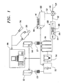
- the cap body applying apparatus of the present invention includes a gas generator 11 for generating a hydrogen-oxygen mixture possessing a 2:1 mixture ratio by electrolyzing water, a tank 12 for holding water, and a water replenishing device 13 for replenishing water to the gas generator 11.
- the gas generator 11 constitutes the gas supplying device for supplying hydrogen-oxygen gas mixture.
- the gas generator 11 is comprised of a plurality of cells and is capable of generating, for example, 100 liters of hydrogen-oxygen mixture when a DC current of 15 A is applied for one hour. Generally speaking, the generator breaks down water by electrolysis into its basic elements of two parts hydrogen and one part oxygen. The generator automatically mixes the hydrogen and oxygen to the optimal combustion ratio of 2:1.
- the hydrogen-oxygen mixture generated by the gas generator 11 is supplied through a filter 14 to a booster 15.
- the filter 14 is designed to clean the gas produced by the generator to remove aerosols, mists, etc. produced during the electrolysis of water.
- the booster 15 consists of one or more tanks which hold methanol.
- the pure hydrogen-oxygen mixture gas mixture flows into the booster where it is enriched with combustible alcohol vapor.
- a hydrogen-oxygen gas mixture rich in methanol gas can be produced by injecting the hydrogen-oxygen gas mixture at the bottom of the booster tank(s).
- the flame temperature is approximately 3200° C.
- the methanol gas-rich hydrogen-oxygen gas mixture although the flame temperature is low at 2500 degrees C, the amount of energy the flame has increases. That is, the combustion of the hydrogen together with the alcohol (methanol) lowers the flame temperature to between about 2500° C and about 2700° C while at the same time increasing or boosting the energy content of the flame.
- the apparatus of the present invention also includes a tank 16 for holding methanol, and a replenishing device 17 for replenishing methanol to the booster 15. While methanol is used in this embodiment, other kinds of alcohol may be used in place of methanol.
- the hydrogen-oxygen gas mixture is sent through a reverse flame check device 20 and a switching valve 21 to a burner unit 22.
- the reverse flame check device 20 is comprised of a cup-shaped filter 25 that is pressed by a spring 26 against an 0-ring 27 so that the flame of the burner unit 22 is prevented from reversing.
- the switching valve 21 is positionable in two positions. In a first position, the switching valve 21 interconnects the lines L1 and L2, and in a second position, the switching valve 21 interconnects the lines L2 and L3. In the first position, the hydrogen-oxygen gas mixture from the booster 15 is supplied to the burner unit 22 for burning. In the second position, air from an air supply device is supplied to the burner unit 22 for extinguishing.
- the burner unit 22 comprises a group or array of nozzles 31, with each nozzle 31 being provided with an opening from which hydrogen-oxygen gas mixture is ejected to create a tiny flame. As a result, a group or array of tiny flames is created.
- An igniter 32 is disposed adjacent one of the nozzles 31 of the nozzle group to ignite all the nozzles 31.
- a flame monitor camera 33 is disposed obliquely above the burner unit 22. At a position obliquely above the burner unit 22 is also disposed a gas detector 34 for detecting gas leakage and troubles or problems in the burner unit 22.
- a controller 35 is also provided for overall control of the gas generator 11, the tanks 12, 16, and the burner unit 22.
- the controller 35 starts the cap body applying apparatus automatically without requiring intervention by an operator.
- the controller 35 also controls the gas generation rate, the amount of hydrogen-oxygen gas mixture that is consumed, and the voltage applied to the gas generator 11.
- the system is designed so that the monitoring results of the flame monitor camera 33 and the detection results of the gas detector 34 are sent to the controller 35.
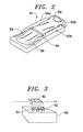
- the cap body 51 that is to be to be applied to the packaging container through use of the apparatus of the present invention is illustrated in FIGS. 2 and 3 .
- the cap body 51 is integrally formed from a resin material such as polyethylene and includes a main part 50 having a generally U-shaped configuration, a pull-tab 52 supported on the main part 50 for turning or pivoting movement about a hinge 54, and a piercing flap 53 also supported on the main part 50 for interlocked turning with the pull-tab 52 about the hinge 54.
- the main part also includes a pull-tab holding portion 50a.
- a detent 50b is formed on the pull-tab holding portion 50a of the main part 50 at a position adjacent the pull tab 52. In this way, the pull-tab 52 is held with the main part 50 by the engagement of the side edge of the pull-tab 52 with the detent 50b. Additional details associated with the construction of the cap body, which details are not necessary for an understanding of the present invention, are described in Japanese Laid-Open Patent Application No. Hei-8-132855 , the disclosure of which is incorporated herein by reference. It is also possible to use the apparatus of the present invention to apply to a packaging container a cap body having a different configuration and construction than that shown in FIGS. 2 and 3 .
- a pickup apparatus which is described below in more detail, is provided for picking up the cap body and subsequently assisting in applying the cap body 51 to the portion of the packaging container to which the cap body is to be applied.
- This pickup apparatus carries the cap body 51 to a position directly above the burner unit 22 as shown in FIG. 3 , and the burner unit 22 then heats the underside periphery of the cap body 51 for a specified period of time.
- the pickup apparatus then carries the cap body 51 to a position where the cap body 51 is pressed against the portion-of the packaging container where the cap body is to be applied.
- the melted polyethylene resin on the underside periphery of the cap body 51 is joined to the polyethylene resin forming the outermost layer on the packaging container surface.
- the cap body 51 is applied to the desired region of the packaging container.
- the periphery of the cap body 51 is melted within a very short period of time. This increases the processing speed of the cap body applying apparatus. Further, the cost of the cap body applying apparatus can be reduced because a special heating apparatus is not required.
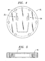
- the various details associated with the burner unit 22 can be seen with reference to FIGS. 4, 5 and 6 .
- the burner unit 22 includes a burner block 41, a plurality of nozzle securing holes 43 formed in the burner block 41, and a plurality of nozzles 31 adapted to be secured in the nozzle securing holes 43 by way of seal members 45.
- the nozzles 31 are preferably made of a material having a low heat conductivity.
- the nozzle securing holes 43 are arranged in a generally U-shaped pattern that generally corresponds in shape to the shape of the underside periphery of the cap body 51.
- the nozzles 31 which are secured in the nozzle securing holes 43 are thus also arranged in a generally U-shaped pattern.
- the nozzle holding holes 43 are arranged in two rows in the portions of the array of holes 43 designated P1 and P2. These portions. P1, P2 correspond in location to the pull-tab holding portion 50a of the cap body 51.
- Each nozzle 31 is constructed as a relatively long pipe of small diameter to create a tiny flame at the tip of each nozzle 31. Since hydrogen-oxygen gas mixture is used as the fuel, the tiny flame created at the tip of each nozzle 31 is stabilized.
- the nozzle holding holes 43 and the nozzles 31 are arranged so that a portion of the arrangement is devoid of holes and nozzles.
- This portion of the hole and nozzle arrangement that is devoid of holes and nozzles corresponds in location to the hinge 54 of the cap body.
- the hinge 54 of the cap body 51 is prevented from being heated and deformed and so the hinge 54 is not inadvertently or accidentally heated by mistake.
- the operation of the hinge 54 on the cap body is not adversely affected.
- the melting of the cap body can be uniform along the cap body periphery.
- the cap body 51 is applied securely to the portion of the packaging container where the cap body 51 is to be applied.
- the process of the present invention results in a high strength connection at the cap body/packaging container interface after the application of the cap body to the packaging container.
- the nozzles are relatively long in length and so the tip of each nozzle 31 is spaced sufficiently far from the surface of the burner block 41.
- This feature coupled with the nozzles 31 being made of a material having a low heat conductivity advantageously prevents the heat of the flame from being transmitted to the burner block 41.
- the nozzles 31 are arranged at constant or generally intervals in a generally U-shaped pattern, all the nozzles 31 are not ignited at the same time with the igniter 32.
- FIGS. 7-9 illustrate the manner in which the nozzles 31 are ignited during operation of the apparatus of the present invention.
- the igniter 32 is activated while the hydrogen-oxygen gas mixture is ejected from all the nozzles 31, only the nozzle 31 (or perhaps several nozzles 31) that is located closest to and immediately adjacent the igniter 32 is ignited as shown in FIG. 8 and the rest of the nozzles 31 are not ignited.
- a shield plate 57 is employed. This shield plate 57 is placed above the nozzles 31 after the nozzle(s) 31 immediately adjacent the igniter 32 is ignited.
- the hydrogen-oxygen gas mixture ejected from the nozzles 31 which are not ignited tends to rise, the mixture is prevented from rising by the shield plate 57 and instead is deflected to spread laterally along with the lateral air flow produced at this time.
- the rest of the nozzles 31 are also subsequently ignited by virtue of the deflected hydrogen-oxygen gas mixture.
- the shield plate 57 includes two shield portions 57a, 57b.
- the shield plate 57 is rotatably supported on a shaft 58 for rotation in the direction of the arrow.
- the shaft 58 is connected to driving device which rotatably drives the shield plate 57 in an intermittent manner so that the shield portions 57a, 57b shield the nozzles 31 from above. More specifically, the shield plate 57 is rotated to shield the nozzles 31 from above after the igniter 31 is activated.
- the nozzle plate 51 positioned above the nozzles advantageously makes it possible to ignite all of the nozzles 31 with a single igniter 32.
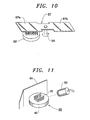
- the present invention employs the flame monitor camera 33 shown in FIG. 1 to monitor the flames.
- FIG. 11 illustrates the way in which the flame monitor camera is positioned 33 in the apparatus of the present invention.
- the flame monitor camera 33 is a CCD camera which recognizes the condition of a plurality of flames as visual data which are analyzed with an analyzing device associated with the controller 35 shown in FIG. 1 to monitor and determine the hue, chroma, and brightness of the flames.
- a visor 61 can be placed behind the burner unit 22 as shown in FIG. 11 . Further, the burner block 41 can be painted black.
- FIG. 12 illustrates in plan view the cap body applying apparatus of the present invention during operation while FIG. 13 sets forth a cap applying process time chart depicting the timing of various operations performed during the cap applying process. As seen with reference to FIG. 12
- the apparatus is provided with a table 71 that is turned by a stepping motor 70 in the direction of arrow D, a plurality of packaging container holders 72 mounted on the table 71 for holding individual packaging containers at spaced apart locations around the circumference of the table 71, a conveyor 73 for continuously transporting the cap bodies 51 in the direction of arrow C utilizing pneumatic pressure, and a retracting device 78 for retracting the burner unit 22 when the apparatus detects that a cap body 51 is not being transported.
- the table 71 functions as a transporting device for transporting the packaging container holders 72 and the held packaging containers.
- the packaging container holders 72 move with rotational movement of the table 71.
- the apparatus also includes a plurality of pickup apparatus 80 that are designed to pick-up the cap body 51 from the positioning device 75.
- a single pickup apparatus 80 is shown in FIG. 12 , there are preferably twelve spaced apart pickup apparatus disposed around the periphery of the table 71 at places corresponding in location to the location of the individual packaging container holders 72.
- the pickup apparatus 80 are mounted on the table 71 so that they rotate with the table 71.
- the table also serves as a transport device for the pickup apparatus 80.
- each pickup apparatus 80 preferably includes a plate 82 connected to a source of vacuum for holding the cap body by vacuum.
- the pickup apparatus 80 is vertically movable in an up and down manner as shown by the double headed arrows in FIG. 14 .
- the apparatus is also provided with a pusher device 84 shown in FIG. 15 .
- the pusher device 84 which is positioned at the cap applying station described below, is designed to push the pickup apparatus 80 downwardly so that the cap body 51 held by the pickup apparatus 80 is applied to the exterior surface of the packaging container 86.
- a packaging container transported in the direction of arrow A is placed in the adjoining packaging container holder 72 and is rotatably transported by intermittent motion in the direction of arrow D through rotational movement of the table 71.
- the table 71 preferably intermittently rotates and stops at twelve locations between the location designated by the arrow A where the packaging containers are loaded into the holders 72 and the location designated by the arrow B where the packaging containers with the applied cap body are discharged from the apparatus.
- a cap body 51 transported by the conveyor 73 in the direction of arrow C is positioned by a positioning device 75 so that the cap body 51 can be picked up by the pickup apparatus 80.
- the pickup apparatus 80 moves downwardly to pick up the cap body 51 positioned by the positioning device 75.
- the pickup apparatus 80 holds the cap body 51 by vacuum and moves upwardly with the held cap body 51.
- the pickup apparatus 80 then transports the cap body 51, through rotation of the table 71, in the circumferential direction of the table 71.
- the cap body 51 is delivered by the pickup apparatus to a heating position where it is positioned over the burner unit 22 so that the underside periphery of the cap body 51 is heated and melted.
- the cap body 51 while still being held by the pickup apparatus, is moved to an applying station.
- the cap body 51 with the heated and melted underside periphery is then pushed downwardly by the pusher device 84, where the cap body 51 is pressed against and applied to the desired portion of the packaging container.
- the packaging container is discharged in the direction of arrow B.
- the burner unit 22 is normally in the forward extended position. However, if the cap body 51 is not being transported, a sensor detects the absence of a cap body 51 and the burner unit 22 is then retracted. Therefore, the pickup apparatus is prevented from being overheated and burned by the burner unit 22.
- FIG. 13 illustrates a timing chart associated with the operation of the apparatus depicted in FIG. 12 .
- the timing chart illustrates the relative timing aspects associated with operation (i.e., "move") and non-operation (i.e., "stop") of the stepping motor 70, the movement of the pusher device 80 between the upper and lower positions, the operation (i.e., "action") and non-operation of the cap positioning device 75, the pickup and holding operations of the pickup apparatus 80, the heating and non-heating action of the burner unit 22, and the forward and retracted positioning of the burner unit.
- a packaging container intermittently advanced from the in-feed location at arrow B stops at the pickup station (1) shown in FIG. 13 .
- the cap positioning device begins to position the cap body 51 where it is picked up by the pickup apparatus 80.
- the pickup apparatus 80 while holding the cap body 51, is then advanced through rotation of the table 71 to station (2) shown in FIG. 13 where the pickup apparatus 80 stops.
- Station (2) is a resting station where the cap body 51 is held by the pickup apparatus 80 until the next intermittent movement of the table 71. Further advance of the pickup apparatus through rotation of the table 71 positions the pickup apparatus 80 at the heating station (3) wherein the table 71 once again stops.
- the cap body 51 being held by the pickup apparatus 80 at the heating station (3) is heated on its underside periphery by the burner unit 22.
- the table 71 and the pickup apparatus 80 holding the cap body 51 with the heated underside periphery are advanced to the applying station (4) and stopped.
- the pickup apparatus 80 is pushed downwardly by the pusher device 84 so that the cap body 51 held by the pickup apparatus 80 is applied to the packaging container.
- the table 71 is rotated to station (5) shown in FIG. 13 where it is stopped.
- Station (5) constitutes another resting station.
- the table 71 is subsequently advanced so that the packaging container with the applied cap body 51 is moved to the out-feed station (6) where the rotation of the table 71 once again stops.
- the packaging container with the attached cap body is discharged from the apparatus.
- the burner unit is retracted to avoid damaging the pickup apparatus.
- the apparatus and method according to the present invention allow realization of a variety of advantages.
- the hydrogen-oxygen gas mixture supplied from the gas generating device is burned in the burner unit, it is not necessary to store the hydrogen-oxygen gas mixture. It is thus possible to reduce the area occupied by the cap body applying apparatus.
- the apparatus is relatively safe should a leak occur.
- a hydrogen-oxygen gas mixture is used as the fuel, it is possible to create a relatively stabilized tiny flame at the tip of each nozzle.
- the nozzles along the profile of the cap body, only the underside periphery of the cap body is heated and melted without heating and melting other undesired portions of the cap body. It is also possible to prevent the hinge portion of the cap body from being inadvertently and undesirably heated and deformed by mistake.
- the melting can be effected in a relatively uniform manner along the periphery of the cap body.
- the cap body is applied securely to the desired portion of the packaging container. This is also advantageous from the standpoint of providing a high strength connection of the cap body to the packaging container while at the same time achieving a good seal after application of the cap body to the packaging container.
- the provision of the shield plate that can be selectively disposed over the nozzles is also quite advantageous in that the plurality of nozzles which are arranged in a pattern that corresponds to the underside periphery of the cap body can be ignited through use of a single igniter.
- the use of the CCD camera for monitoring the flame of each of the nozzles is highly useful in that it makes it possible to simultaneously monitor all of the flames emitted by the plurality of nozzles that are arranged in a pattern that corresponds to the shape of the underside periphery of the cap body.
Landscapes
- Engineering & Computer Science (AREA)
- Mechanical Engineering (AREA)
- Closing Of Containers (AREA)
- Vacuum Packaging (AREA)
- Closures For Containers (AREA)
- Auxiliary Devices For And Details Of Packaging Control (AREA)
Claims (20)
- Vorrichtung zum Zuführen und Anbringen von Kappenkörpern an einem Verpackungsbehälter, umfassend:eine Aufnahmevorrichtung (80) zum Transportieren eines Kappenkörpers (51) in eine Erwärmungsposition,
gekennzeichnet durcheine Gasversorgungsvorrichtung (11) zum Zuführen eines Wasserstoff-Sauerstoff-Gasgemischs, das durch Elektrolysieren von Wasser erhalten wird;eine Brennereinheit (22), die mit der Gasversorgungsvorrichtung (11) zum Aufnehmen des Wasserstoff-Sauerstoff-Gasgemischs von der Gasversorgungsvorrichtung (11) und Verbrennen des Wasserstoff-Sauerstoff-Gasgemischs verbunden ist;wobei die Brennereinheit (22) mit mehreren Düsen (31) versehen ist, die in einem Muster angeordnet sind, das in Bezug auf die Form einem unteren Rand des Kappenkörpers (51) entspricht, wobei jede der Düsen eine winzige Flamme erzeugt und die Aufnahmevorrichtung (80) den Kappenkörper (51) in eine Erwärmungsposition über der Brennereinheit (22) transportiert. - Vorrichtung nach Anspruch 1, gekennzeichnet durch eine Schutzplatte (57), die über den Düsen (31) positioniert werden kann, um das Wasserstoff-Sauerstoff-Gasgemisch umzulenken, das aus den Düsen abgegeben wird, wobei ein Zünder (32) benachbart einer der Düsen angeordnet ist.
- Vorrichtung nach Anspruch 1, gekennzeichnet durch eine CCD-Kamera (33) zum Überwachen der Flamme, die aus jeder der Düsen abgegeben wird.
- Vorrichtung nach Anspruch 3, gekennzeichnet durch einen Gasdetektor (34) zum Ermitteln von Gasleckagen.
- Vorrichtung nach Anspruch 4, gekennzeichnet durch eine Steuerung (35), mit der die CCD-Kamera (33) und der Gasdetektor (34) verbunden sind.
- Vorrichtung nach Anspruch 1, dadurch gekennzeichnet, dass die Brennereinheit einen Brennerblock (41) mit mehreren Löchern (43) aufweist, wobei jede der Düsen in einem der Löcher positioniert ist.
- Vorrichtung nach Anspruch 1, wobei die Aufnahmevorrichtung an einer Transportvorrichtung (71) befestigt ist und die Aufnahmevorrichtung von der Transportvorrichtung in die Erwärmungsposition über der Brennereinheit transportiert wird, um zu ermöglichen, dass die unterseitige Oberfläche des Kappenkörpers von der Flamme aus den Düsen erwärmt wird und von der Erwärmungsposition in eine Anbringungsposition transportiert wird, in welcher der Kappenkörper an einem Verpackungsbehälter angebracht wird; und
einen Verpackungsbehälterhalter (72) zum Halten eines Verpackungsbehälters, an dem der Kappenkörper angebracht werden soll. - Vorrichtung nach Anspruch 7, gekennzeichnet durch eine Schutzplatte (57), die über den Düsen positioniert werden kann, um das Gasgemisch, das aus den Düsen abgegeben wird, umzulenken.
- Vorrichtung nach Anspruch 7, dadurch gekennzeichnet, dass die Düsen in einem im Allgemeinen U-förmigen Muster angeordnet sind.
- Vorrichtung nach Anspruch 7, dadurch gekennzeichnet, dass der Verpackungsbehälterhalter an der Transportvorrichtung (71) befestigt ist.
- Vorrichtung nach Anspruch 10, dadurch gekennzeichnet, dass die Transportvorrichtung (71) ein Drehtisch ist.
- Verfahren zum Anbringen eines Kappenkörpers (51) an einem Verpackungsbehälter, umfassend: Positionieren eines Kappenkörpers (51) mit einer unterseitigen Oberfläche, so dass Wärme auf den Kappenkörper aufgebracht wird, dadurch gekennzeichnet, dass
der Kappenkörper benachbart einer Brennereinheit (22) positioniert wird, die mehrere Düsen (31) aufweist, die jede eine winzige Flamme abgeben, wobei die Düsen (31) in einem Muster angeordnet sind, das in Bezug auf die Form dem unterseitigen Rand des Kappenkörpers (51) entspricht;
Erwärmen der unterseitigen Oberfläche des Kappenkörpers (51) mit den Flammen, die aus den Düsen (31) der Brennereinheit (22) abgegeben werden; und
Anbringen des Kappenkörpers (51) mit der erwärmten unterseitigen Oberfläche an einem Verpackungsbehälter, um den Kappenkörper an dem Verpackungsbehälter zu befestigen. - Verfahren nach Anspruch 12, dadurch gekennzeichnet, dass die Düsen (31) in einem im Allgemeinen U-förmigen Muster angeordnet werden.
- Verfahren nach Anspruch 12, dadurch gekennzeichnet, dass der Kappenkörper (51) von einer Fördervorrichtung (73) in eine Position bewegt wird, in welcher der Kappenkörper von einer Aufnahmevorrichtung (80) aufgenommen wird.
- Verfahren nach Anspruch 4, dadurch gekennzeichnet, dass der Kappenkörper in eine Position benachbart der Brennereinheit durch Drehung eines Tisches (71) transportiert wird, auf dem die Aufnahmevorrichtung (80) befestigt ist.
- Verfahren nach Anspruch 12, dadurch gekennzeichnet, dass der Verpackungsbehälter von einem Drehtisch (71) mit Unterbrechungen und in drehbarer Weise fortbewegt wird.
- Verfahren nach Anspruch 12, gekennzeichnet durch das Entzünden aller Düsen mit einem einzigen Zünder (32).
- Verfahren nach Anspruch 12, dadurch gekennzeichnet, dass die Flammen, die von den Düsen erzeugt werden, durch Verbrennen eines Wasserstoff-Sauerstoff-Gemischs erzeugt werden, wobei das Wasserstoff-SauerstoffGemisch, das aus den Düsen abgegeben wird, von einem Schutzschild (57) umgelenkt wird.
- Verfahren nach Anspruch 12, gekennzeichnet durch das Zurückziehen der Brennereinheit, sobald die Abwesenheit eines Kappenkörpers benachbart der Brennereinheit festgestellt wird.
- Verfahren nach Anspruch 12, gekennzeichnet durch das Überwachen der Flammen, die von den Düsen abgegeben werden, mit einer CCD-Kamera (33).
Applications Claiming Priority (3)
| Application Number | Priority Date | Filing Date | Title |
|---|---|---|---|
| JP21234096A JP3748630B2 (ja) | 1996-08-12 | 1996-08-12 | 蓋体取付装置 |
| JP21234096 | 1996-08-12 | ||
| PCT/US1997/014128 WO1998006628A1 (en) | 1996-08-12 | 1997-08-11 | Cap applying apparatus |
Publications (3)
| Publication Number | Publication Date |
|---|---|
| EP1021340A1 EP1021340A1 (de) | 2000-07-26 |
| EP1021340A4 EP1021340A4 (de) | 2003-01-22 |
| EP1021340B1 true EP1021340B1 (de) | 2009-10-07 |
Family
ID=16620926
Family Applications (1)
| Application Number | Title | Priority Date | Filing Date |
|---|---|---|---|
| EP97937207A Expired - Lifetime EP1021340B1 (de) | 1996-08-12 | 1997-08-11 | Vorrichtung zum anbringen von verschlusskappen |
Country Status (8)
| Country | Link |
|---|---|
| EP (1) | EP1021340B1 (de) |
| JP (1) | JP3748630B2 (de) |
| KR (1) | KR100487226B1 (de) |
| CN (1) | CN1091721C (de) |
| AU (1) | AU3977497A (de) |
| DE (1) | DE69739613D1 (de) |
| TW (1) | TW343187B (de) |
| WO (1) | WO1998006628A1 (de) |
Families Citing this family (3)
| Publication number | Priority date | Publication date | Assignee | Title |
|---|---|---|---|---|
| ATE427269T1 (de) * | 2005-12-19 | 2009-04-15 | Tetra Laval Holdings & Finance | Verfahren und vorrichtung zum auftragen von klebstoff auf eine ausgusstulle zum anbringen derselbe an packungen mit fliessfahigen nahrungsmitteln |
| WO2009032190A2 (en) * | 2007-08-28 | 2009-03-12 | Transphorm, Inc. | Compact electric appliance for providing gas for combustion |
| US20110139661A1 (en) * | 2009-12-10 | 2011-06-16 | Giaia Lee Ludwig | Blister packaging container and method |
Family Cites Families (7)
| Publication number | Priority date | Publication date | Assignee | Title |
|---|---|---|---|---|
| US2284631A (en) * | 1940-03-22 | 1942-06-02 | Anchor Hocking Glass Corp | Method and apparatus for sealing containers |
| US2387439A (en) * | 1942-02-05 | 1945-10-23 | Crown Cork & Seal Co | Method of sealing containers |
| US2518856A (en) * | 1946-08-27 | 1950-08-15 | Anchor Hocking Glass Corp | Method and apparatus for sealing containers |
| US2551476A (en) * | 1949-03-31 | 1951-05-01 | American Seal Kap Corp | Transfer means for thermoplastic caps, having means to heat said caps during transfer |
| US2618424A (en) * | 1950-07-06 | 1952-11-18 | Anchor Hocking Glass Corp | Sealing machine |
| US3128215A (en) * | 1961-07-13 | 1964-04-07 | Procter & Gamble | Method and apparatus for sealing a thermoplastic top to a tubular body |
| CH421740A (de) * | 1962-11-03 | 1966-09-30 | Seitz Werke Gmbh | Verfahren und Vorrichtung zum sterilen Verschliessen von Gefässen, insbesondere mit Naturkorken |
-
1996
- 1996-08-12 JP JP21234096A patent/JP3748630B2/ja not_active Expired - Fee Related
-
1997
- 1997-08-11 CN CN97198499A patent/CN1091721C/zh not_active Expired - Lifetime
- 1997-08-11 AU AU39774/97A patent/AU3977497A/en not_active Abandoned
- 1997-08-11 WO PCT/US1997/014128 patent/WO1998006628A1/en not_active Ceased
- 1997-08-11 KR KR10-1999-7001844A patent/KR100487226B1/ko not_active Expired - Lifetime
- 1997-08-11 DE DE69739613T patent/DE69739613D1/de not_active Expired - Lifetime
- 1997-08-11 EP EP97937207A patent/EP1021340B1/de not_active Expired - Lifetime
- 1997-08-12 TW TW086111548A patent/TW343187B/zh not_active IP Right Cessation
Also Published As
| Publication number | Publication date |
|---|---|
| EP1021340A4 (de) | 2003-01-22 |
| DE69739613D1 (de) | 2009-11-19 |
| CN1091721C (zh) | 2002-10-02 |
| JP3748630B2 (ja) | 2006-02-22 |
| AU3977497A (en) | 1998-03-06 |
| KR100487226B1 (ko) | 2005-05-03 |
| JPH1059305A (ja) | 1998-03-03 |
| CN1232431A (zh) | 1999-10-20 |
| HK1022456A1 (zh) | 2000-08-11 |
| WO1998006628A1 (en) | 1998-02-19 |
| EP1021340A1 (de) | 2000-07-26 |
| TW343187B (en) | 1998-10-21 |
| KR20000030019A (ko) | 2000-05-25 |
Similar Documents
| Publication | Publication Date | Title |
|---|---|---|
| US6192660B1 (en) | Cap applying apparatus | |
| CN101269717B (zh) | 机动车辆的燃料罐系统和将阀门元件焊接至燃料罐的方法 | |
| US5749201A (en) | Laser bonded tamper proof press-on cap and seal | |
| US7810537B2 (en) | Apparatus and method for sealing a vertical protrusion on a roof | |
| CA2101715C (en) | Method of and apparatus for sealing containers | |
| JPH082512A (ja) | 筒状フィルムの製造方法及びその装置 | |
| EP1021340A1 (de) | Vorrichtung zum anbringen von verschlusskappen | |
| US6370842B1 (en) | Wrapping material processor and process for manufacturing packing container | |
| CN211077194U (zh) | 一种垃圾袋打包机构及垃圾桶 | |
| CN101198523A (zh) | 饮料用或食品用密封容器的制造方法 | |
| JP3692717B2 (ja) | カップ式飲料自動販売機 | |
| JPH04215928A (ja) | 包装容器用の超過圧弁をシールする方法と装置 | |
| JP4833713B2 (ja) | 密封容器の製造方法 | |
| US20040045257A1 (en) | Container centering device | |
| JP3079693B2 (ja) | ホットメルトインク供給装置 | |
| HK1022456B (en) | Cap applying apparatus | |
| JP4855120B2 (ja) | 密封容器の製造方法、容器密封システム及び蓋溶接機 | |
| US20030015274A1 (en) | Reflective hood for heat-shrinking film onto an open-topped container and method of using same | |
| JP4056763B2 (ja) | 上蓋開蓋装置 | |
| US20030061922A1 (en) | Method and apparatus for cutting film for heat-shrinking | |
| JPH11115906A (ja) | 蓋体取付装置 | |
| CN219770606U (zh) | 一种便于开启封口膜且防漏墨的墨水瓶 | |
| KR101923467B1 (ko) | 레토르트용 페이스트 제품 포장방법 | |
| KR200187115Y1 (ko) | 퓨즈 납땜시스템 | |
| CN220721512U (zh) | 一种发热模组和辅助封口支架可自动移动的封口机装置 |
Legal Events
| Date | Code | Title | Description |
|---|---|---|---|
| PUAI | Public reference made under article 153(3) epc to a published international application that has entered the european phase |
Free format text: ORIGINAL CODE: 0009012 |
|
| 17P | Request for examination filed |
Effective date: 19990129 |
|
| AK | Designated contracting states |
Kind code of ref document: A1 Designated state(s): DE FR GB IT |
|
| A4 | Supplementary search report drawn up and despatched |
Effective date: 20021205 |
|
| AK | Designated contracting states |
Kind code of ref document: A4 Designated state(s): DE FR GB IT |
|
| RIC1 | Information provided on ipc code assigned before grant |
Free format text: 7B 65B 63/08 A, 7B 65B 7/28 B |
|
| 17Q | First examination report despatched |
Effective date: 20061117 |
|
| GRAP | Despatch of communication of intention to grant a patent |
Free format text: ORIGINAL CODE: EPIDOSNIGR1 |
|
| GRAJ | Information related to disapproval of communication of intention to grant by the applicant or resumption of examination proceedings by the epo deleted |
Free format text: ORIGINAL CODE: EPIDOSDIGR1 |
|
| GRAP | Despatch of communication of intention to grant a patent |
Free format text: ORIGINAL CODE: EPIDOSNIGR1 |
|
| GRAS | Grant fee paid |
Free format text: ORIGINAL CODE: EPIDOSNIGR3 |
|
| GRAA | (expected) grant |
Free format text: ORIGINAL CODE: 0009210 |
|
| AK | Designated contracting states |
Kind code of ref document: B1 Designated state(s): DE FR GB IT |
|
| REG | Reference to a national code |
Ref country code: GB Ref legal event code: FG4D |
|
| REF | Corresponds to: |
Ref document number: 69739613 Country of ref document: DE Date of ref document: 20091119 Kind code of ref document: P |
|
| PLBE | No opposition filed within time limit |
Free format text: ORIGINAL CODE: 0009261 |
|
| STAA | Information on the status of an ep patent application or granted ep patent |
Free format text: STATUS: NO OPPOSITION FILED WITHIN TIME LIMIT |
|
| 26N | No opposition filed |
Effective date: 20100708 |
|
| REG | Reference to a national code |
Ref country code: FR Ref legal event code: PLFP Year of fee payment: 19 |
|
| REG | Reference to a national code |
Ref country code: FR Ref legal event code: PLFP Year of fee payment: 20 |
|
| PGFP | Annual fee paid to national office [announced via postgrant information from national office to epo] |
Ref country code: GB Payment date: 20160810 Year of fee payment: 20 Ref country code: DE Payment date: 20160802 Year of fee payment: 20 Ref country code: IT Payment date: 20160822 Year of fee payment: 20 |
|
| PGFP | Annual fee paid to national office [announced via postgrant information from national office to epo] |
Ref country code: FR Payment date: 20160712 Year of fee payment: 20 |
|
| REG | Reference to a national code |
Ref country code: DE Ref legal event code: R071 Ref document number: 69739613 Country of ref document: DE |
|
| REG | Reference to a national code |
Ref country code: GB Ref legal event code: PE20 Expiry date: 20170810 |
|
| PG25 | Lapsed in a contracting state [announced via postgrant information from national office to epo] |
Ref country code: GB Free format text: LAPSE BECAUSE OF EXPIRATION OF PROTECTION Effective date: 20170810 |