EP1020604A2 - Schiebetüranlage - Google Patents
Schiebetüranlage Download PDFInfo
- Publication number
- EP1020604A2 EP1020604A2 EP00100781A EP00100781A EP1020604A2 EP 1020604 A2 EP1020604 A2 EP 1020604A2 EP 00100781 A EP00100781 A EP 00100781A EP 00100781 A EP00100781 A EP 00100781A EP 1020604 A2 EP1020604 A2 EP 1020604A2
- Authority
- EP
- European Patent Office
- Prior art keywords
- fixed field
- sliding door
- support
- door system
- wing
- Prior art date
- Legal status (The legal status is an assumption and is not a legal conclusion. Google has not performed a legal analysis and makes no representation as to the accuracy of the status listed.)
- Granted
Links
- 239000011521 glass Substances 0.000 claims abstract description 27
- 241000591215 Acraea andromacha Species 0.000 claims description 8
- 239000000725 suspension Substances 0.000 claims description 6
- 238000005452 bending Methods 0.000 claims description 3
- 230000000903 blocking effect Effects 0.000 claims description 2
- 238000010276 construction Methods 0.000 description 7
- 125000006850 spacer group Chemical group 0.000 description 5
- 230000003287 optical effect Effects 0.000 description 3
- 229910000831 Steel Inorganic materials 0.000 description 2
- 238000007665 sagging Methods 0.000 description 2
- 239000010959 steel Substances 0.000 description 2
- 238000004873 anchoring Methods 0.000 description 1
- 230000004888 barrier function Effects 0.000 description 1
- 230000015572 biosynthetic process Effects 0.000 description 1
- 238000006073 displacement reaction Methods 0.000 description 1
- 238000005553 drilling Methods 0.000 description 1
- 238000000034 method Methods 0.000 description 1
- 230000036316 preload Effects 0.000 description 1
- 238000007639 printing Methods 0.000 description 1
- 230000001012 protector Effects 0.000 description 1
- 238000007789 sealing Methods 0.000 description 1
Images


Classifications
-
- E—FIXED CONSTRUCTIONS
- E05—LOCKS; KEYS; WINDOW OR DOOR FITTINGS; SAFES
- E05D—HINGES OR SUSPENSION DEVICES FOR DOORS, WINDOWS OR WINGS
- E05D15/00—Suspension arrangements for wings
- E05D15/06—Suspension arrangements for wings for wings sliding horizontally more or less in their own plane
- E05D15/0621—Details, e.g. suspension or supporting guides
- E05D15/0626—Details, e.g. suspension or supporting guides for wings suspended at the top
- E05D15/0656—Bottom guides
-
- E—FIXED CONSTRUCTIONS
- E05—LOCKS; KEYS; WINDOW OR DOOR FITTINGS; SAFES
- E05D—HINGES OR SUSPENSION DEVICES FOR DOORS, WINDOWS OR WINGS
- E05D15/00—Suspension arrangements for wings
- E05D15/06—Suspension arrangements for wings for wings sliding horizontally more or less in their own plane
- E05D15/0621—Details, e.g. suspension or supporting guides
- E05D15/0626—Details, e.g. suspension or supporting guides for wings suspended at the top
- E05D15/0652—Tracks
-
- E—FIXED CONSTRUCTIONS
- E05—LOCKS; KEYS; WINDOW OR DOOR FITTINGS; SAFES
- E05F—DEVICES FOR MOVING WINGS INTO OPEN OR CLOSED POSITION; CHECKS FOR WINGS; WING FITTINGS NOT OTHERWISE PROVIDED FOR, CONCERNED WITH THE FUNCTIONING OF THE WING
- E05F15/00—Power-operated mechanisms for wings
- E05F15/60—Power-operated mechanisms for wings using electrical actuators
- E05F15/603—Power-operated mechanisms for wings using electrical actuators using rotary electromotors
- E05F15/632—Power-operated mechanisms for wings using electrical actuators using rotary electromotors for horizontally-sliding wings
- E05F15/643—Power-operated mechanisms for wings using electrical actuators using rotary electromotors for horizontally-sliding wings operated by flexible elongated pulling elements, e.g. belts, chains or cables
-
- E—FIXED CONSTRUCTIONS
- E05—LOCKS; KEYS; WINDOW OR DOOR FITTINGS; SAFES
- E05Y—INDEXING SCHEME ASSOCIATED WITH SUBCLASSES E05D AND E05F, RELATING TO CONSTRUCTION ELEMENTS, ELECTRIC CONTROL, POWER SUPPLY, POWER SIGNAL OR TRANSMISSION, USER INTERFACES, MOUNTING OR COUPLING, DETAILS, ACCESSORIES, AUXILIARY OPERATIONS NOT OTHERWISE PROVIDED FOR, APPLICATION THEREOF
- E05Y2800/00—Details, accessories and auxiliary operations not otherwise provided for
- E05Y2800/10—Additional functions
- E05Y2800/12—Sealing
-
- E—FIXED CONSTRUCTIONS
- E05—LOCKS; KEYS; WINDOW OR DOOR FITTINGS; SAFES
- E05Y—INDEXING SCHEME ASSOCIATED WITH SUBCLASSES E05D AND E05F, RELATING TO CONSTRUCTION ELEMENTS, ELECTRIC CONTROL, POWER SUPPLY, POWER SIGNAL OR TRANSMISSION, USER INTERFACES, MOUNTING OR COUPLING, DETAILS, ACCESSORIES, AUXILIARY OPERATIONS NOT OTHERWISE PROVIDED FOR, APPLICATION THEREOF
- E05Y2800/00—Details, accessories and auxiliary operations not otherwise provided for
- E05Y2800/15—Applicability
- E05Y2800/16—Applicable on combinations of fixed and movable wings
-
- E—FIXED CONSTRUCTIONS
- E05—LOCKS; KEYS; WINDOW OR DOOR FITTINGS; SAFES
- E05Y—INDEXING SCHEME ASSOCIATED WITH SUBCLASSES E05D AND E05F, RELATING TO CONSTRUCTION ELEMENTS, ELECTRIC CONTROL, POWER SUPPLY, POWER SIGNAL OR TRANSMISSION, USER INTERFACES, MOUNTING OR COUPLING, DETAILS, ACCESSORIES, AUXILIARY OPERATIONS NOT OTHERWISE PROVIDED FOR, APPLICATION THEREOF
- E05Y2800/00—Details, accessories and auxiliary operations not otherwise provided for
- E05Y2800/26—Form or shape
- E05Y2800/27—Profiles; Strips
-
- E—FIXED CONSTRUCTIONS
- E05—LOCKS; KEYS; WINDOW OR DOOR FITTINGS; SAFES
- E05Y—INDEXING SCHEME ASSOCIATED WITH SUBCLASSES E05D AND E05F, RELATING TO CONSTRUCTION ELEMENTS, ELECTRIC CONTROL, POWER SUPPLY, POWER SIGNAL OR TRANSMISSION, USER INTERFACES, MOUNTING OR COUPLING, DETAILS, ACCESSORIES, AUXILIARY OPERATIONS NOT OTHERWISE PROVIDED FOR, APPLICATION THEREOF
- E05Y2900/00—Application of doors, windows, wings or fittings thereof
- E05Y2900/10—Application of doors, windows, wings or fittings thereof for buildings or parts thereof
- E05Y2900/13—Type of wing
- E05Y2900/132—Doors
Definitions
- the invention relates to a sliding door system, preferably automatic sliding door or telescopic sliding door system, with at least one motor-driven Sliding door leaf and at least one fixed fixed field leaf, with a drive and drive and control devices, namely drive motor, Control and preferably also with a guided over pulleys circulating drive belt, driver for connecting drive belts and wing, locking and motion detector, with one on both ends Stationarily supported horizontal support on which the drive can be mounted.
- a drive and drive and control devices namely drive motor, Control and preferably also with a guided over pulleys circulating drive belt, driver for connecting drive belts and wing, locking and motion detector, with one on both ends Stationarily supported horizontal support on which the drive can be mounted.
- a sliding door system is known from DE-OS 197 08 437, the main components of which are especially carrier and drive, are modular.
- a drive module is attached to a carrier module and via a clamping device associated with this.
- the carrier module is in turn on a stationary Mullion and transom construction assembled and can additionally by one or more Fixed field wings are supported.
- the arrangement shown has, in particular in the front or rear view, a relatively large height, because below and possibly also above the transom, which like the drive is a relative one has low overall height, still parts of the beam support and / or the fixed field sash frame are visible and thus visually increase the overall height of the transom.
- the invention has for its object a sliding door system with less Develop height, especially when installing this sliding door system in a Mullion-transom construction with transparent skylight wings, as with these Arrangements of the horizontal ledger, at the height of which the drive is mounted, should appear as narrow as possible.
- the horizontal support has at least one support on the fixed field wing, the horizontal Beam the upper horizontal edge of the fixed field wing in the manner of a frame overlaps and with at least one load-bearing vertical frame spar underneath Formation of an external frame of the fixed field wing connected is that the support is arranged in the area of the vertical supporting frame spar or the horizontal support on one between parallel panes of glass the fixed field wing arranged support is supported.
- the horizontal girder By supporting the horizontal girder on the fixed field wing, the horizontal girder can be made relatively narrow, ie have a relatively low overall height with at the same time relatively low bending stiffness, the support on the fixed field wing
- the horizontal support is prevented from sagging.
- the overlapping in the manner of a frame results in optical advantages, since the optical doubling of the upper frame profile by the horizontal support, which is known from prior art, is eliminated.
- the concealed anchoring of the horizontal beam in the frameless fixed field wing results in the same optical advantages, ie a narrow and transparent arrangement.
- the horizontal beam can prevent deflection mounted preloaded, i.e. the horizontal beam is in front of the Assembly of the drive profile and the drive mounted so that it is as long as the drive profile and the drive are not installed, bend upwards is biased.
- This bias is preferably carried out by means of a clampable screw, which forms the support, or by means of a finely adjustable Blocking device in the area of the support, so that the deflection the horizontal beam when loaded by the sliding sash and / or the drive is counteracted.
- the drive profile can be attached to the intermediate carrier profile.
- the drive profile can also be attached directly to the horizontal support to be assembled.
- a panel can be installed, for example by clipping onto a corresponding clip holder of the carrier, so that there is a visually appealing design of the invention Sliding door system, especially in the rear view.
- the horizontal beam visually matches the surrounding mullion-transom construction by means of this panel to adjust.
- Alternative to clip fastening are however other types of attachment for the panel are also conceivable.
- the skylight device in preferred embodiments on the supported horizontal carrier.
- the fixed field wing has at least one glass pane and can be framed Glass wing with an all-round frame that overlaps the glass pane his.
- the frame has upper and lower horizontal frame bars and side vertical frame bars.
- the upper horizontal frame spar of the fixed field wing is formed by the horizontal beam by passing through it is replaced.
- the horizontal beam directly overlaps the upper horizontal Edge of the glass pane of the fixed field wing.
- a vertical frame spar of the Fixed field wing is on a vertical side wall or on a vertical post anchorable.
- the lower horizontal frame spar is on a fixed one Supportable bottom rail.
- Tensioning device used as a tension rope, tension band, tension wire or the like can be formed, the at least one glass pane of the Fixed field wing in the area of its upper horizontal edge, especially not fully assembled state of the fixed field wing or during transport and the assembly process.
- the tensioning device is supported by the horizontal Carrier gripped over when the fixed field wing is installed and thus covered.
- the fixed field wing can be used as a so-called frameless glass wing arranged between the at least two panes of glass Spacer, with between the at least two glass panes in the outer Edge area at least in sections arranged wearing and / or Edge closure element and possibly in the area of the spacer and / or the support and / or edge closure element applied to the glass panes Edge printing or the like may be formed.
- the support and / or edge closure element has a receiving groove in which the support engages.
- the support is designed so that it preferably in a form-fitting manner in the receiving groove of the horizontal support and / or Edge closure element is added and via a clamp connection is set in this.
- the horizontal support engages in a preferred Embodiment between parallel panes of the skylight device one, with one between the panes on the lower horizontal Edge of the skylight device arranged support and / or edge closure element is connectable.
- the horizontal support can be hung on the skylight device.
- numerous suspension points preferably by suspension along the entire extent of the lower support and / or edge closure element, a uniform introduction of force into the glass wing of the skylight device is achieved and thus a Sagging "of the horizontal beam avoided.
- the attachment of the horizontal beam also on vertical posts, for example vertical posts of a post-and-beam construction, respectively.
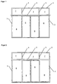
- FIG. 1 shows a sliding door system built into a mullion-transom construction consisting of horizontal transoms 2a, 2b and vertical mullions 3a, 3b, 3c, 3d.
- the glazed sliding sashes 5 are guided in a rail that is not visible here because the cover rail 4 concealed by the drive 4 conceals a horizontally displaceable rail.
- the passage area, which is released or blocked by the sliding sash 5, is laterally delimited by two fixed, likewise glazed fixed field sash 6.
- Three glazed skylights 7 are arranged above the transom 2b, at the height of which the drive 4 is mounted.
- the drive is completely covered by the bolt 2b.
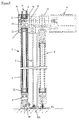
- the fixed field wing 6 is designed as a framed glass wing, consisting of two parallel glass panes 8, two vertical frame spars 9, 10 and a lower horizontal frame spar 11.
- the tensioning device 12, 13 consists of two tensioning blocks 12, which are designed as flat steel and engage in corresponding undercut grooves of the vertical frame spars 9, 10 and are fixed there by means of clamping, and a tensioning cable 13, the ends of which are firmly connected to the tensioning blocks 12 .
- the tensioning device 12, 13 in particular prevents the glazing 8 from falling out of the frame 9, 10 when the cover profile 1b is not mounted.
- the vertical frame spars 9, 10 are connected to the lower horizontal frame spar 11 by means of screw connections.
- the vertical frame spar 10 which laterally delimits the passage area has a vertically running threaded bore 10a, in which one with a Lock nut 19a engages provided screw.
- This screw serves as a support 19 for the horizontal support 1a and is by means of the lock nut at the desired Support of the horizontal beam 1 a fixable.
- Adjustment of the support 19 is a variable adjustment of a preload of the horizontal beam 1a, 1b possible against deflection.
- a holding profile 16 is mounted on the fixed wall for fastening the end face of the horizontal support 1a on the wall.
- a support profile 17 is fastened to the holding profile 16 by means of a screw connection, on which the horizontal support 1 a rests with its lower horizontal edges in the region of its front ends.
- a web 1c of the horizontal support 1a engages in a corresponding groove in the support profile 17 in a form-fitting manner.
- This provides secure support for the end faces of the horizontal support 1a, in particular when the horizontal support 1a is loaded by tilting moments.
- the tilting moments arise from one-sided, eccentric loading of the horizontal support 1a by the mass of the sliding sash 5 and by the mass of the drive 4th
- An intermediate support profile is attached to the horizontal support 1 a by means of a screw connection 20 attached to which a suspension device for a drive is formed is.
- the drive 4 and the sliding sash are mounted on the drive 5 slidably suspended.
- the fixed field wing 6 is supported with its lower horizontal frame spar 11 on a fixed floor rail 15 by the lower horizontal frame spar 11 overlapping the floor rail 15 and, as can be seen in particular in FIG. 7 , with a screw connection which connects the lower horizontal frame spar 11 and the floor rail 15 reaches through, is secured against horizontal displacement.
- the fixed field wing 6 Since the fixed field wing 6 does not have an upper horizontal frame spar, it engages with the upper horizontal edge of the glass panes 8 only with the interposition of an edge protection 23, which is generally used for framed glass panes and is arranged on the outer edge of the glass panes 8, in that composed of the support profile 1a and cover profile 1b horizontal carrier formed receiving groove 1f, see in particular Figure 5.
- the horizontal carrier composed of support profile 1a and cover profile 1b furthermore has a receiving groove 1e on the top side, in which the glass panes 8 of the fixed field wing 7 with their lower horizontal edge with the interposition of a correspondingly Intervene edge protector 23.
- the support profile 1a and the cover profile 1b are horizontally aligned with each other in a common plane.
- the cover profile 1b is mounted on the support profile 1a of the horizontal support by means of a screw connection with a horizontally directed screw.
- the cover profile 1b has a shape to which a panel 21 can be clipped.
- FIG. 6 shows the upper area of the vertical frame spar 10, which delimits the passage area, with the support 19 of the horizontal support 1a.
- the horizontal beam lies with its web 1c on the support 19 designed as a hexagon screw.
- the support 19 is supported in the vertical frame spar 10 by the hexagon screw engaging in a vertical threaded hole in the vertical frame spar 10.
- the receiving groove 1f formed by the assembled horizontal support 1a, 1b is covered by a clip-in, U-shaped cover 22 above the passage area.
- FIG. 8 The top view of this exemplary embodiment described in FIG. 8 shows the wall-side mounting of the vertical frame spar 9, which is fastened in a C-shaped receiving profile 14.
- the vertical frame spar 10 delimiting the passage area contributes, as in Sliding doors known, a seal 25, which in the closed state of the Sliding wing 5 seals the sliding wing 5 with respect to the fixed field wing 6.
- the sealing lip of the seal 25 is then on a correspondingly shaped Extension of the corresponding vertical frame spar of the sliding sash 5 on.
- the vertical frame spar delimiting the passage area carries 10 of the fixed field wing 6, as is known in automatic sliding doors, one Sensor 24, which e.g. is designed as a light barrier and closing the Sliding sash 6 in the presence of an obstacle in the passage area of the Sliding door system prevents or interrupts.
- the bottom rail 15 is formed in several parts in this embodiment.
- the section of the floor rail 15 carrying the fixed field wing points in the region near the vertical frame spar 10 delimiting the passage area Extension with a parallel to the longitudinal axis of the sliding door system Tooth 15a.
- This extension is made by one with a corresponding one Toothed extension of a lower sliding guide 15 c overlapped, so that the lower sliding guide 15 c perpendicular to the longitudinal axis the sliding door system is adjustable and thereby the distance between Fixed field wing 6 and sliding wing 5 can be variably adjusted.
- the establishment of the lower sliding guide 15c is carried out by screwing to the bottom rail 15, the screw connection an elongated hole 15b in the extension of the lower Grips sliding guide 15c and presses the toothed areas against each other.
- Figure 9 shows a modified embodiment of a sliding door system according to the invention, wherein the horizontal support 1a, 1b is mounted directly on a stationary wall section.
- This wall section can be, for example, a lintel located above the passage area, but in alternative exemplary embodiments (not shown here) it can also be horizontal bolts or the like.
- the profile 1a of the horizontal beam 1a, 1b is mounted on the fixed wall, which is directed parallel to the door plane.
- An intermediate support profile 20 is fastened to the profile 1b of the horizontal support 1a, 1b, which is connected by screwing to the profile 1a of the horizontal support 1a, 1b, a plurality of screw connections preferably being provided since the intermediate support profile 20 is attached has no self-supporting property.
- a suspension device 20a for a running gear profile 33 is formed on the intermediate carrier profile 20.
- the drive 4 is in turn mounted on the drive profile 33 and the sliding leaf 5 is slidably suspended.
- the receiving grooves 1e, 1f formed by the assembled horizontal support 1a, 1b possibly, but not shown here, enable the assembly of fixed field wings 6 and / or fanlight wings 7.
- FIG. 10 shows a further alternative exemplary embodiment of a sliding door system according to the invention.
- this sliding door system has two horizontal supports 1 a arranged one above the other.
- the two horizontal beams 1a are positively connected to one another by means of a connecting profile 27, in that a web 1c of the upper horizontal carrier 1a positively engages in a groove 27b of the connecting profile 27 and a web 27a of the connecting profile 27 positively engages in a groove 1d of the lower horizontal carrier 1a .
- connection profile 27 The connection of the horizontal beam 1a with the connection profile 27 is here not shown, it can for example be a screw and / or clamp connection act. Furthermore, as in the previous embodiments shown on the support profiles 1a of the horizontal support cover profiles 1b mounted; it is also a one-piece cover profile with a Overall height, which is the total overall height of the horizontal ones arranged one above the other Carrier 1a essentially corresponds, conceivable, the one-piece cover profile covers both support profiles 1b of the horizontal beam.
- the arrangement of this embodiment is particularly suitable for use in sliding door systems, which have relatively heavy leaves and / or a relatively have heavy drive, so that a single narrow horizontal beam the weight could not absorb without deflection.
- the exemplary embodiment according to FIGS. 11 and 12 shows a telescopic sliding door system in which the sliding leaves 5, the fixed field leaves 6 and the skylight leaves 7 are designed as frameless glass leaves.
- the glass wings consist of two glass panes 8 arranged parallel to one another, which are connected to one another by a spacer 28 which runs around the edge region of the glass panes 8.
- the spacer 28 is arranged set back from the outer edges of the glass panes 8, so that a support and / or edge closure element 29 is arranged in the free space present here.
- the support and / or edge closure elements 29 are also arranged all around in the form of an upper horizontal spar, two lateral vertical spars and a lower horizontal spar.
- a receiving groove for receiving fitting parts is formed in the carrying and / or edge closing element 29; the carrying and / or edge closing elements 29 on the upper horizontal pane edges each have a C-shaped undercut receiving groove, while the receiving grooves of the carrying and / or edge closing elements 29 are U-shaped on the lower horizontal pane edges.
- C-shaped undercut grooves are also possible here.
- the fixed field wing 6 is supported with its lower horizontal support and / or Edge termination element 29 on a stationary bottom rail 15, the Receiving groove of this support and / or edge closure element 29 the bottom rail engages so that the bottom rail 15 in the receiving groove of the carrying and / or Edge termination element 29 engages.
- an L-shaped fastening bracket 30 is fastened, which the horizontal support 1a with the upper support and / or edge closure element 29 of the fixed field wing 6 connects.
- the mounting bracket 30 will by a clamp connection with a in the receiving groove of the upper carrying and / or Edge closure element 29 located flat steel and is with the vertical leg of the mounting bracket 30 by means of a horizontally directed Screwed screw, the mounting bracket 30 preferably in the area of the vertical edge which laterally delimits the passage area the fixed field wing 6 is arranged so that the horizontal support 1a on the Fixed field wing 6 is at least supported and the weight of the horizontal Carrier 1a in the vertical support and / or edge closure element 29 of the Fixed field wing 6 is initiated.
- Mounting bracket 30 possible in other positions.
- the frontal attachment of the horizontal support 1a is preferably analogous to that in the figures 3 to 8 embodiment shown.
- the L-shaped mounting bracket 30 can also be used in the exemplary embodiments Groove of the lateral vertical, arranged in the area of the passage Carrying and / or edge closure element 29 of the fixed field wing 6 may be attached.
- the frameless skylight 7 present in this exemplary embodiment becomes by means of a further fastening bracket 31 and horizontally directed screws fixed on the horizontal support 1a.
- the mounting bracket engages in the receiving groove of the lower horizontal support and / or edge closure element 29 of the skylight 7.
- the mounting bracket 31 is by a front panel 32, which is flush with the surfaces of the fixed field wing 6 and of the skylight 7, covered.
- the upper horizontal edge of the skylight 7 is with a pin 34, which in the upper support and / or edge closure element 29 of the skylight 7 is attached and engages in a fixed bolt 2, held.
- the intermediate support profile 20 is attached to the horizontal support 1a analogous to the embodiment shown in Figures 3 to 8.
- On the intermediate beam profile 20 is a drive profile with two parallel running side by side Track systems for the telescopic sliding sash 5 mounted.
- To the Drive profile is connected to the drive 4 on the side.
- the use of the construction according to the invention of the horizontal support 1a, 1b is except for the sliding door or Telescopic sliding door systems also - but not shown here - for folding door, Arch sliding door and revolving door systems conceivable.
- the attachment of the horizontal support 1a, 1b also on vertical posts 3a, 3b, 3c, 3d, for example vertical posts 3a, 3b, 3c, 3d of a post-and-beam construction, respectively.
Landscapes
- Engineering & Computer Science (AREA)
- Mechanical Engineering (AREA)
- Power-Operated Mechanisms For Wings (AREA)
Abstract
Description

- Fig. 1
- eine Frontansicht einer Schiebetüranlage mit gerahmten Schiebe- und Festfeldflügeln;
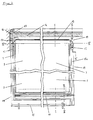
- Fig. 2
- eine Rückansicht der Schiebetüranlage gemäß Figur 1;
- Fig. 3
- eine geschnittene Frontansicht eines gerahmten Festfeldflügels einer Schiebetüranlage mit auf dem Festfeldflügel abgestütztem horizontalen Träger;
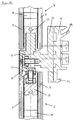
- Fig. 4
- eine Schnittansicht einer Schiebetüranlage mit gerahmten Schiebe- und Festfeldflügeln; Schnitt entlang Linie I - I in Fig. 3;
- Fig. 5
- eine vergrößerte Einzelheit (im Bereich des horizontalen Trägers) in Fig. 4;
- Fig. 6
- eine Schnittansicht des horizontalen Trägers im Bereich der Abstützung durch den vertikalen Rahmenholm des Festfeldflügels gemäß des Ausführungsbeispiels in Figur 3; Schnitt entlang Linie II - II in Fig. 3;
- Fig. 7
- eine Schnittansicht der Bodenschiene mit darauf befestigtem unteren Rahmenholm des Festfeldflügels gemäß des Ausführungsbeispiels in Figur 3; Schnitt entlang Linie III - III in Fig. 3;
- Fig. 8
- eine geschnittene Draufsicht auf den gerahmten Festfeldflügel gemäß des Ausführungsbeispiels in Figur 3; Schnitt entlang Linie IV - IV in Fig. 3;
- Fig. 9
- eine Fig. 4 entsprechende Schnittansicht eines abgewandelten Ausführungsbeispiels einer Schiebetüranlage mit unmittelbar an einer Frontwand montiertem horizontalen Träger;
- Fig. 10
- eine Fig. 4 und 9 entsprechende Schnittansicht eines weiteren abgewandelten Ausführungsbeispiels einer Schiebetüranlage mit zwei übereinander angeordneten, miteinander verbundenen horizontalen Trägern;
- Fig. 11
- eine Fig. 4, 9 und 10 entsprechende Schnittansicht einer Teleskopschiebetüranlage mit rahmenlosen Schiebe- und Festfeldflügeln;
- Fig. 12
- eine vergrößerte Einzelheit (im Bereich des horizontalen Trägers) in Fig. 11.
- 1a
- Tragprofil des horizontalen Trägers
- 1b
- Deckprofil des horizontalen Trägers
- 1c
- Steg
- 1d
- Nut
- 1e
- Aufnahmenut
- 1f
- Aufnahmenut
- 2a
- Riegel
- 2b
- Riegel
- 3a
- Pfosten
- 3b
- Pfosten
- 3c
- Pfosten
- 3d
- Pfosten
- 4
- Antrieb
- 4a
- Abdeckhaube
- 5
- Schiebeflügel
- 6
- Festfeldflügel
- 7
- Oberlichtflügel
- 8
- Glasscheibe
- 9
- vertikaler Rahmenholm
- 10
- vertikaler Rahmenholm
- 10a
- Bohrung
- 11
- unterer horizontaler Rahmenholm
- 12
- Spannklotz
- 13
- Spannseil
- 14
- Aufnahmeprofil
- 15
- Bodenschiene
- 15a
- Verzahnung
- 15b
- Langloch
- 15c
- untere Schiebeführung
- 16
- Halteprofil
- 17
- Stützprofil
- 18
- Befestigungsprofil
- 19
- Auflager
- 19a
- Kontermutter
- 20
- Zwischenträgerprofil
- 21
- Blende
- 22
- Blende
- 23
- Kantenschutz
- 24
- Sensor
- 25
- Dichtung
- 26
- Verschraubung
- 27
- Verbindungsprofil
- 27a
- Steg
- 27b
- Nut
- 28
- Abstandshalter
- 29
- Trage- und/oder Randabschlußelement
- 30
- Befestigungswinkel
- 31
- Befestigungswinkel
- 32
- Blende
- 33
- Laufwerkprofil
- 34
- Stift
Claims (20)
- Schiebetüranlage, vorzugsweise automatische Schiebetür- oder Teleskopschiebetüranlage,mit mindestens einem motorisch angetriebenen Schiebetürflügel und mindestens einem feststehenden Festfeldflügel,mit einem Laufwerk sowie Antriebs- und Steuerungseinrichtungen, nämlich Antriebsmotor, Steuerung und vorzugsweise auch mit einem über Umlenkrollen geführten umlaufenden Treibriemen, Mitnehmer zur Verbindung von Treibriemen und Flügel, Verriegelung und Bewegungsmelder,mit einem an beiden Stirnseiten ortsfest abgestützten horizontalen Träger, an dem das Laufwerk montierbar ist
dadurch gekennzeichnet,daß der horizontale Träger (1a, 1b) auf dem Festfeldflügel (6) mindestens ein Auflager (19, 30) aufweist,
wobei der horizontale Träger (1a, 1b) die obere horizontale Kante des Festfeldflügels (6) in Art eines Rahmens übergreift und mit mindestens einem tragenden vertikalen Rahmenholm (10) unter Ausbildung eines außen aufliegenden Rahmens des Festfeldflügels (6) so verbunden ist, daß das Auflager (19) im Bereich des vertikalen tragenden Rahmenholms (10) angeordnet ist, oderder horizontale Träger (1a, 1b) auf einem zwischen parallelen Glasscheiben (8) des Festfeldflügels (6) angeordneten Auflager (30) abgestützt ist. - Schiebetüranlage, vorzugsweise mit gerahmtem Festfeldflügel, nach Anspruch 1, dadurch gekennzeichnet,daß der Festfeldflügel (6) mindestens eine Glasscheibe (8) aufweist und der horizontale Träger (1a, 1b) unmittelbar die obere horizontale Kante der Glasscheibe (8) übergreift.
- Schiebetüranlage, vorzugsweise mit gerahmtem Festfeldflügel, nach Anspruch 1 oder 2, dadurch gekennzeichnet,daß der Festfeldflügel (6) als gerahmter Glasflügel ausgebildet ist mit oberen horizontalen Rahmenholmen und unteren horizontalen Rahmenholmen (11) und seitlichen vertikalen Rahmenholmen (9, 10), vorzugsweise als umlaufender, übergreifender Rahmen ausgebildet,daß der obere horizontale Rahmenholm durch den horizontalen Träger (1a, 1b) gebildet wird, vorzugsweise durch diesen ersetzt wird.
- Schiebetüranlage, vorzugsweise mit gerahmtem Festfeldflügel, nach einem der vorhergehenden Ansprüche, dadurch gekennzeichnet,daß ein vertikaler Rahmenholm (9) des Festfeldflügels (6) an einer ortsfesten vertikalen Seitenwand oder an einem ortsfesten vertikalen Pfosten (3) verankerbar ist.
- Schiebetüranlage, vorzugsweise mit gerahmtem Festfeldflügel, nach einem der vorhergehenden Ansprüche, dadurch gekennzeichnet,daß ein Stirnende, vorzugsweise beide Stirnenden des horizontalen Trägers (1a, 1b) an einer ortsfesten Wand befestigbar ist/sind, vorzugsweise mittels eines Halteprofils (16).
- Schiebetüranlage, vorzugsweise mit gerahmtem Festfeldflügel, nach einem der vorhergehenden Ansprüche, dadurch gekennzeichnet,daß der untere horizontale Rahmenholm (11) auf einer ortsfesten Bodenschiene (15) abstützbar ist.
- Schiebetüranlage, vorzugsweise mit gerahmtem Festfeldflügel, nach einem der vorhergehenden Ansprüche, dadurch gekennzeichnet,daß eine zwischen den vertikalen Rahmenholmen (9, 10) des Festfeldflügels (6) angeordnete Spanneinrichtung (12, 13), vorzugsweise ein Spannseil (13), Spannband, Spanndraht oder dergleichen, eine oder mehrere Glasscheiben (8) des Festfeldflügels (6) im Bereich ihrer oberen horizontalen Kante haltert.
- Schiebetüranlage, vorzugsweise mit gerahmtem Festfeldflügel, nach Anspruch 7, dadurch gekennzeichnet,daß die Spanneinrichtung (12, 13) durch den horizontalen Träger (1a, 1b) bei montiertem Zustand des Festfeldflügels (6) übergriffen wird.
- Schiebetüranlage, vorzugsweise mit rahmenlosem Festfeldflügel, nach Anspruch 1, dadurch gekennzeichnet,daß das Auflager (30) in einem zwischen den Glasscheiben (8) des Festfeldflügels angeordneten horizontalen Trage- und/oder Randabschlußelement (29) abgestützt ist.
- Schiebetüranlage, vorzugsweise mit rahmenlosem Festfeldflügel, nach Anspruch 9, dadurch gekennzeichnet,daß das Trage- und/oder Randabschlußelement (29) eine Aufnahmenut aufweist, in die das Auflager (30) eingreift, vorzugsweise darin aufgenommen ist.
- Schiebetüranlage, vorzugsweise mit rahmenlosem Festfeldflügel, nach Anspruch 9 oder 10, dadurch gekennzeichnet,daß das Auflager (30) in dem Trage- und/oder Randabschlußelement (29) über eine Klemmverbindung festgelegt ist.
- Schiebetüranlage, vorzugsweise mit rahmenlosem Festfeldflügel, nach einem der vorangehenden Ansprüche, insbesondere nach einem der Ansprüche 9 bis 11, dadurch gekennzeichnet,daß der horizontale Träger (1a, 1b) zwischen parallele Scheiben (8) einer oberhalb des Schiebeflügels (5) und/oder Festfeldflügels (6) angeordneten Oberlichteinrichtung (7) eingreift, vorzugsweise mit einem zwischen den Scheiben (8) angeordneten Trage- und/oder Randabschlußelement (29) verbindbar.
- Schiebetüranlage, vorzugsweise mit rahmenlosem Festfeldflügel, nach einem der Ansprüche 9 bis 12, dadurch gekennzeichnet,daß im Bereich der unteren horizontalen Kante der parallelen Glasscheiben (8) des Festfeldflügels (6) ein unteres horizontales Trage- und/oder Randabschlußelement (29) angeordnet ist, das unmittelbar oder mittelbar auf einem ortsfesten Bodenlager, vorzugsweise Bodenschiene (15), abstützbar ist.
- Schiebetüranlage nach einem der vorhergehenden Ansprüche, dadurch gekennzeichnet,daß das Auflager (19, 30) im Bereich einer vertikalen Begrenzungskante des Festfeldflügels (6) angeordnet ist, vorzugsweise im Bereich der Begrenzungskante des Durchgangsbereichs.
- Schiebetüranlage nach einem der vorhergehenden Ansprüche, dadurch gekennzeichnet,daß zwischen dem horizontalen Träger (1a, 1b) und einem Profil des Laufwerks ein Zwischenträgerprofil (20) angeordnet ist, vorzugsweise mit einer Aufhängeeinrichtung, um das Profil des Laufwerks am Zwischenträgerprofil (20) einzuhängen.
- Schiebetüranlage vorzugsweise nach einem der vorhergehenden Ansprüche, dadurch gekennzeichnet,daß der horizontale Träger (1a, 1b) gegen Durchbiegung vorgespannt montierbar ist, vorzugsweise mittels einer Verklotzungseinrichtung.
- Schiebetüranlage nach einem der vorhergehenden Ansprüche, dadurch gekennzeichnet,daß auf dem horizontalen Träger (1a, 1b) eine Oberlichteinrichtung (7) abgestützt ist.
- Schiebetüranlage vorzugsweise nach einem der vorhergehenden Ansprüche, dadurch gekennzeichnet,daß der horizontale Träger (1a, 1b) an einer Oberlichteinrichtung (7), die sich oberhalb des Schiebeflügels (5) und/oder Festfeldflügels (6) erstreckt, einhängbar ist.
- Schiebetüranlage nach einem der vorhergehenden Ansprüche, dadurch gekennzeichnet,daß an der Frontseite des horizontalen Trägers (1a, 1b) eine Blende (21, 32) montierbar ist.
- Schiebetüranlage nach einem der vorhergehenden Ansprüche, dadurch gekennzeichnet,daß eine sich an der Unterseite des horizontalen Trägers (1a, 1b) befindliche Aufnahmenut (1f), zur Aufnahme von Abschnitten und/oder Beschlagteilen des Festfeldflügels (6) ausgebildet ist, durch eine Blende (22) verdeckbar ist, vorzugsweise oberhalb des Durchgangsbereichs.
Applications Claiming Priority (2)
| Application Number | Priority Date | Filing Date | Title |
|---|---|---|---|
| DE19901768 | 1999-01-18 | ||
| DE19901768A DE19901768A1 (de) | 1999-01-18 | 1999-01-18 | Schiebetüranlage |
Publications (3)
| Publication Number | Publication Date |
|---|---|
| EP1020604A2 true EP1020604A2 (de) | 2000-07-19 |
| EP1020604A3 EP1020604A3 (de) | 2003-04-23 |
| EP1020604B1 EP1020604B1 (de) | 2015-07-29 |
Family
ID=7894612
Family Applications (1)
| Application Number | Title | Priority Date | Filing Date |
|---|---|---|---|
| EP00100781.4A Expired - Lifetime EP1020604B1 (de) | 1999-01-18 | 2000-01-15 | Schiebetüranlage |
Country Status (3)
| Country | Link |
|---|---|
| EP (1) | EP1020604B1 (de) |
| DE (1) | DE19901768A1 (de) |
| ES (1) | ES2545825T3 (de) |
Cited By (1)
| Publication number | Priority date | Publication date | Assignee | Title |
|---|---|---|---|---|
| EP3460152A1 (de) * | 2017-09-25 | 2019-03-27 | dormakaba Deutschland GmbH | Bodenschiene für ein schiebetürsystem, schiebetürelement für ein schiebetürsystem sowie schiebetürsystem |
Families Citing this family (2)
| Publication number | Priority date | Publication date | Assignee | Title |
|---|---|---|---|---|
| DE102006030782B4 (de) * | 2006-06-30 | 2016-02-18 | Geze Gmbh | Rahmenlose Trennwand sowie Verfahren zur Montage einer rahmenlosen Trennwand |
| DE202018106790U1 (de) | 2018-11-29 | 2020-04-09 | Agtatec Ag | Automatisches Türsystem, insbesondere in Form einer Schiebetür oder einer Teleskopschiebetür oder einer Falttür und ein Gebäude mit einem solchen automatischen Türsystem |
Citations (1)
| Publication number | Priority date | Publication date | Assignee | Title |
|---|---|---|---|---|
| DE19708437A1 (de) | 1996-03-01 | 1997-10-30 | Geze Gmbh & Co | Schiebetüranlage |
Family Cites Families (4)
| Publication number | Priority date | Publication date | Assignee | Title |
|---|---|---|---|---|
| US3834081A (en) * | 1973-03-30 | 1974-09-10 | Gyro Tech Inc | Automatic sliding door system |
| DE9014754U1 (de) * | 1990-04-14 | 1991-01-03 | W. Hartmann & Co (Gmbh & Co), 2000 Hamburg | Verankerungsvorrichtung für optisch rahmenlose Verglasungen |
| DE19733415B4 (de) * | 1996-08-01 | 2006-10-12 | Geze Gmbh | Anordnung bestehend aus einer Tür oder einem Fenster und einem Fassadenelement oder einem Festfeldflügel |
| WO1999022104A1 (de) * | 1997-10-29 | 1999-05-06 | Geze Gmbh | Baukastensystem zur erstellung von tür- oder fensterantrieben |
-
1999
- 1999-01-18 DE DE19901768A patent/DE19901768A1/de not_active Withdrawn
-
2000
- 2000-01-15 ES ES00100781.4T patent/ES2545825T3/es not_active Expired - Lifetime
- 2000-01-15 EP EP00100781.4A patent/EP1020604B1/de not_active Expired - Lifetime
Patent Citations (1)
| Publication number | Priority date | Publication date | Assignee | Title |
|---|---|---|---|---|
| DE19708437A1 (de) | 1996-03-01 | 1997-10-30 | Geze Gmbh & Co | Schiebetüranlage |
Cited By (1)
| Publication number | Priority date | Publication date | Assignee | Title |
|---|---|---|---|---|
| EP3460152A1 (de) * | 2017-09-25 | 2019-03-27 | dormakaba Deutschland GmbH | Bodenschiene für ein schiebetürsystem, schiebetürelement für ein schiebetürsystem sowie schiebetürsystem |
Also Published As
| Publication number | Publication date |
|---|---|
| EP1020604B1 (de) | 2015-07-29 |
| DE19901768A1 (de) | 2000-07-20 |
| ES2545825T3 (es) | 2015-09-16 |
| EP1020604A3 (de) | 2003-04-23 |
Similar Documents
| Publication | Publication Date | Title |
|---|---|---|
| DE19733367B4 (de) | Flügel für eine Tür, ein Fenster oder dergleichen | |
| EP0883726B1 (de) | Schiebetüranlage | |
| DE19950656A1 (de) | Fahrzeugtür, insbesondere Kraftfahrzeugtür | |
| EP0552721B1 (de) | Klappflügelfenster | |
| DE19744832C2 (de) | Anordnung für den Einbau eines Fensterrahmens | |
| EP1020604B1 (de) | Schiebetüranlage | |
| EP3677746A1 (de) | Profileinheit zur rollladenführung und befestigung wenigstens eines absturzsicherungselements an einem blendrahmen oder pfosten eines fensters | |
| DE102005030757B4 (de) | Schiebetüranlage | |
| DE202019102112U1 (de) | Profileinheit zur Rollladenführung und Befestigung wenigstens eines Absturzsicherungselements an einem Blendrahmen oder Pfosten eines Fensters | |
| DE102004043000A1 (de) | Fahrzeugtür | |
| EP1039091A2 (de) | Verkleidung für eine Wand- oder Dachfläche | |
| DE19953774B4 (de) | Tür oder Fenster mit einem Tür- oder Fensterflügel und einem über dem Tür- oder Fensterflügel angeordneten Oberlichtöffner | |
| DE19839379A1 (de) | Horizontale Schiebetür | |
| EP0730074B1 (de) | Kantriegelbeschlag für Standflügel von doppelflügeligen Türen | |
| EP3348731B1 (de) | Pfosten-riegel-konstruktion | |
| EP0853179B1 (de) | Flügel für eine Tür, ein Fenster oder dergleichen | |
| DE10023762C2 (de) | Beschlag für einen Glasflügel | |
| CH655762A5 (en) | Folding sliding part for external and internal walls of buildings | |
| DE10120002C1 (de) | An einem Festteil einer Schiebetür angeschlossene Laufschienenanordnung | |
| EP2060723A2 (de) | Mehrflügelige Schiebetür | |
| DE19952250A1 (de) | Automatische Bogenschiebetüranlage | |
| DE3718876A1 (de) | Feststehendes fenster an einer kraftfahrzeugtuer | |
| CH690040A5 (de) | Fenster mit gegen Wettereinwirkung geschützten Flügelrahmen. | |
| DE9016617U1 (de) | Hebeschiebetür | |
| DE3150128A1 (de) | Treibstangenverschluss fuer fenster und tueren, insbesondere dreh - kippfenster, tueren od. dgl. |
Legal Events
| Date | Code | Title | Description |
|---|---|---|---|
| PUAI | Public reference made under article 153(3) epc to a published international application that has entered the european phase |
Free format text: ORIGINAL CODE: 0009012 |
|
| AK | Designated contracting states |
Kind code of ref document: A2 Designated state(s): AT BE CH CY DE DK ES FI FR GB GR IE IT LI LU MC NL PT SE |
|
| AX | Request for extension of the european patent |
Free format text: AL;LT;LV;MK;RO;SI |
|
| PUAL | Search report despatched |
Free format text: ORIGINAL CODE: 0009013 |
|
| AK | Designated contracting states |
Designated state(s): AT BE CH CY DE DK ES FI FR GB GR IE IT LI LU MC NL PT SE |
|
| AX | Request for extension of the european patent |
Extension state: AL LT LV MK RO SI |
|
| RIC1 | Information provided on ipc code assigned before grant |
Ipc: 7E 05F 15/14 A Ipc: 7E 05D 15/06 B Ipc: 7E 06B 3/00 B |
|
| 17P | Request for examination filed |
Effective date: 20030924 |
|
| AKX | Designation fees paid |
Designated state(s): AT BE CH CY DE DK ES FI FR GB GR IE IT LI LU MC NL PT SE |
|
| 17Q | First examination report despatched |
Effective date: 20031230 |
|
| REG | Reference to a national code |
Ref country code: DE Ref legal event code: R079 Ref document number: 50016412 Country of ref document: DE Free format text: PREVIOUS MAIN CLASS: E05F0015140000 Ipc: E05F0015643000 |
|
| RIC1 | Information provided on ipc code assigned before grant |
Ipc: E05F 15/643 20150101AFI20150203BHEP Ipc: E05D 15/06 20060101ALI20150203BHEP |
|
| GRAP | Despatch of communication of intention to grant a patent |
Free format text: ORIGINAL CODE: EPIDOSNIGR1 |
|
| INTG | Intention to grant announced |
Effective date: 20150318 |
|
| GRAS | Grant fee paid |
Free format text: ORIGINAL CODE: EPIDOSNIGR3 |
|
| GRAA | (expected) grant |
Free format text: ORIGINAL CODE: 0009210 |
|
| AK | Designated contracting states |
Kind code of ref document: B1 Designated state(s): AT BE CH CY DE DK ES FI FR GB GR IE IT LI LU MC NL PT SE |
|
| REG | Reference to a national code |
Ref country code: GB Ref legal event code: FG4D Free format text: NOT ENGLISH |
|
| REG | Reference to a national code |
Ref country code: CH Ref legal event code: EP |
|
| REG | Reference to a national code |
Ref country code: AT Ref legal event code: REF Ref document number: 739446 Country of ref document: AT Kind code of ref document: T Effective date: 20150815 |
|
| REG | Reference to a national code |
Ref country code: IE Ref legal event code: FG4D Free format text: LANGUAGE OF EP DOCUMENT: GERMAN |
|
| REG | Reference to a national code |
Ref country code: DE Ref legal event code: R096 Ref document number: 50016412 Country of ref document: DE |
|
| REG | Reference to a national code |
Ref country code: ES Ref legal event code: FG2A Ref document number: 2545825 Country of ref document: ES Kind code of ref document: T3 Effective date: 20150916 |
|
| REG | Reference to a national code |
Ref country code: SE Ref legal event code: TRGR |
|
| REG | Reference to a national code |
Ref country code: NL Ref legal event code: FP |
|
| REG | Reference to a national code |
Ref country code: FR Ref legal event code: PLFP Year of fee payment: 17 |
|
| PG25 | Lapsed in a contracting state [announced via postgrant information from national office to epo] |
Ref country code: GR Free format text: LAPSE BECAUSE OF FAILURE TO SUBMIT A TRANSLATION OF THE DESCRIPTION OR TO PAY THE FEE WITHIN THE PRESCRIBED TIME-LIMIT Effective date: 20151030 |
|
| PG25 | Lapsed in a contracting state [announced via postgrant information from national office to epo] |
Ref country code: PT Free format text: LAPSE BECAUSE OF FAILURE TO SUBMIT A TRANSLATION OF THE DESCRIPTION OR TO PAY THE FEE WITHIN THE PRESCRIBED TIME-LIMIT Effective date: 20151130 |
|
| PG25 | Lapsed in a contracting state [announced via postgrant information from national office to epo] |
Ref country code: DK Free format text: LAPSE BECAUSE OF FAILURE TO SUBMIT A TRANSLATION OF THE DESCRIPTION OR TO PAY THE FEE WITHIN THE PRESCRIBED TIME-LIMIT Effective date: 20150729 |
|
| REG | Reference to a national code |
Ref country code: DE Ref legal event code: R097 Ref document number: 50016412 Country of ref document: DE |
|
| PLBE | No opposition filed within time limit |
Free format text: ORIGINAL CODE: 0009261 |
|
| STAA | Information on the status of an ep patent application or granted ep patent |
Free format text: STATUS: NO OPPOSITION FILED WITHIN TIME LIMIT |
|
| 26N | No opposition filed |
Effective date: 20160502 |
|
| PG25 | Lapsed in a contracting state [announced via postgrant information from national office to epo] |
Ref country code: LU Free format text: LAPSE BECAUSE OF FAILURE TO SUBMIT A TRANSLATION OF THE DESCRIPTION OR TO PAY THE FEE WITHIN THE PRESCRIBED TIME-LIMIT Effective date: 20160115 |
|
| PG25 | Lapsed in a contracting state [announced via postgrant information from national office to epo] |
Ref country code: MC Free format text: LAPSE BECAUSE OF FAILURE TO SUBMIT A TRANSLATION OF THE DESCRIPTION OR TO PAY THE FEE WITHIN THE PRESCRIBED TIME-LIMIT Effective date: 20150729 |
|
| REG | Reference to a national code |
Ref country code: IE Ref legal event code: MM4A |
|
| REG | Reference to a national code |
Ref country code: FR Ref legal event code: PLFP Year of fee payment: 18 |
|
| PG25 | Lapsed in a contracting state [announced via postgrant information from national office to epo] |
Ref country code: IE Free format text: LAPSE BECAUSE OF NON-PAYMENT OF DUE FEES Effective date: 20160115 |
|
| REG | Reference to a national code |
Ref country code: FR Ref legal event code: PLFP Year of fee payment: 19 |
|
| PG25 | Lapsed in a contracting state [announced via postgrant information from national office to epo] |
Ref country code: CY Free format text: LAPSE BECAUSE OF FAILURE TO SUBMIT A TRANSLATION OF THE DESCRIPTION OR TO PAY THE FEE WITHIN THE PRESCRIBED TIME-LIMIT Effective date: 20150729 |
|
| PGFP | Annual fee paid to national office [announced via postgrant information from national office to epo] |
Ref country code: DE Payment date: 20190131 Year of fee payment: 20 Ref country code: NL Payment date: 20190121 Year of fee payment: 20 Ref country code: FR Payment date: 20190123 Year of fee payment: 20 Ref country code: ES Payment date: 20190226 Year of fee payment: 20 Ref country code: IT Payment date: 20190124 Year of fee payment: 20 Ref country code: FI Payment date: 20190122 Year of fee payment: 20 Ref country code: GB Payment date: 20190121 Year of fee payment: 20 Ref country code: CH Payment date: 20190123 Year of fee payment: 20 |
|
| PGFP | Annual fee paid to national office [announced via postgrant information from national office to epo] |
Ref country code: SE Payment date: 20190121 Year of fee payment: 20 Ref country code: AT Payment date: 20190122 Year of fee payment: 20 Ref country code: BE Payment date: 20190121 Year of fee payment: 20 |
|
| REG | Reference to a national code |
Ref country code: NL Ref legal event code: MK Effective date: 20200114 Ref country code: DE Ref legal event code: R071 Ref document number: 50016412 Country of ref document: DE |
|
| REG | Reference to a national code |
Ref country code: GB Ref legal event code: PE20 Expiry date: 20200114 |
|
| REG | Reference to a national code |
Ref country code: FI Ref legal event code: MAE |
|
| REG | Reference to a national code |
Ref country code: BE Ref legal event code: MK Effective date: 20200115 |
|
| REG | Reference to a national code |
Ref country code: SE Ref legal event code: EUG |
|
| REG | Reference to a national code |
Ref country code: AT Ref legal event code: MK07 Ref document number: 739446 Country of ref document: AT Kind code of ref document: T Effective date: 20200115 |
|
| PG25 | Lapsed in a contracting state [announced via postgrant information from national office to epo] |
Ref country code: GB Free format text: LAPSE BECAUSE OF EXPIRATION OF PROTECTION Effective date: 20200114 |
|
| REG | Reference to a national code |
Ref country code: ES Ref legal event code: FD2A Effective date: 20200805 |
|
| PG25 | Lapsed in a contracting state [announced via postgrant information from national office to epo] |
Ref country code: ES Free format text: LAPSE BECAUSE OF EXPIRATION OF PROTECTION Effective date: 20200116 |