EP1020267B2 - Steuerungsvorrichtung für einen Trockner in einer Anlage zur Herstellung von Gipsbauplatten - Google Patents
Steuerungsvorrichtung für einen Trockner in einer Anlage zur Herstellung von Gipsbauplatten Download PDFInfo
- Publication number
- EP1020267B2 EP1020267B2 EP00300338A EP00300338A EP1020267B2 EP 1020267 B2 EP1020267 B2 EP 1020267B2 EP 00300338 A EP00300338 A EP 00300338A EP 00300338 A EP00300338 A EP 00300338A EP 1020267 B2 EP1020267 B2 EP 1020267B2
- Authority
- EP
- European Patent Office
- Prior art keywords
- dryer
- load
- water
- segments
- segment
- Prior art date
- Legal status (The legal status is an assumption and is not a legal conclusion. Google has not performed a legal analysis and makes no representation as to the accuracy of the status listed.)
- Expired - Lifetime
Links
- 238000004519 manufacturing process Methods 0.000 title claims abstract description 71
- 229910052602 gypsum Inorganic materials 0.000 title claims abstract description 30
- 239000010440 gypsum Substances 0.000 title claims abstract description 30
- XLYOFNOQVPJJNP-UHFFFAOYSA-N water Substances O XLYOFNOQVPJJNP-UHFFFAOYSA-N 0.000 claims abstract description 65
- 238000000034 method Methods 0.000 claims abstract description 26
- 238000001704 evaporation Methods 0.000 claims abstract description 17
- 230000008020 evaporation Effects 0.000 claims abstract description 17
- 238000001035 drying Methods 0.000 claims description 19
- 238000012546 transfer Methods 0.000 claims description 12
- 230000002250 progressing effect Effects 0.000 claims description 2
- 230000001419 dependent effect Effects 0.000 claims 2
- 238000010438 heat treatment Methods 0.000 claims 1
- 239000008186 active pharmaceutical agent Substances 0.000 description 8
- 239000000203 mixture Substances 0.000 description 7
- 238000009472 formulation Methods 0.000 description 6
- 238000010586 diagram Methods 0.000 description 5
- 239000000654 additive Substances 0.000 description 3
- 238000004886 process control Methods 0.000 description 3
- 238000006243 chemical reaction Methods 0.000 description 2
- 238000005520 cutting process Methods 0.000 description 2
- 238000012986 modification Methods 0.000 description 2
- 230000004048 modification Effects 0.000 description 2
- 230000004075 alteration Effects 0.000 description 1
- 238000013461 design Methods 0.000 description 1
- 238000009826 distribution Methods 0.000 description 1
- 239000006260 foam Substances 0.000 description 1
- 239000000446 fuel Substances 0.000 description 1
- 230000036571 hydration Effects 0.000 description 1
- 238000006703 hydration reaction Methods 0.000 description 1
- 238000012423 maintenance Methods 0.000 description 1
- 238000012544 monitoring process Methods 0.000 description 1
- 238000012552 review Methods 0.000 description 1
- 239000002002 slurry Substances 0.000 description 1
Images


Classifications
-
- B—PERFORMING OPERATIONS; TRANSPORTING
- B28—WORKING CEMENT, CLAY, OR STONE
- B28B—SHAPING CLAY OR OTHER CERAMIC COMPOSITIONS; SHAPING SLAG; SHAPING MIXTURES CONTAINING CEMENTITIOUS MATERIAL, e.g. PLASTER
- B28B11/00—Apparatus or processes for treating or working the shaped or preshaped articles
- B28B11/24—Apparatus or processes for treating or working the shaped or preshaped articles for curing, setting or hardening
Definitions
- the present invention relates to a dryer control system for use in manufacturing gypsum board.
- Gypsum board is produced by extruding a gypsum, water and foam slurry between two continuous paper sheets, cutting the resulting ribbon into boards, and passing the boards through a board dryer.
- a gypsum board manufacturing process there has been a move to automate the gypsum board manufacturing process.
- dryer control has been done by measuring moisture content of the gypsum boards as they exit the dryer and manually adjusting the dryer temperature accordingly.
- An example of such a board drying process can be seen in EP-A-0 042 349.
- such a procedure relies on trial and error and operator skill and attentiveness, especially when changes in board formulation occur.
- a gypsum board drying device as defined in claim 13.
- the preferred embodiment takes the form of a dryer control system and method wherein the load of boards to be provided to the dryer is divided up into successive segments.
- a desired amount of water to be evaporated from each segment is determined based on the amount of water used to produce each segment.
- the desired amount of water to be evaporated from each segment is used as a basis for continuously calculating the evaporation load for the dryer and controlling the amount of energy provided to the dryer accordingly.
- Figure 1 shows a simplified schematic plan view of a gypsum board production line, illustrated generally by reference numeral 10.
- the basic components of the production line 10 shown in Figure 1 are well known and include upper and lower paper rolls 12 and 14, mixer station 16, forming belt 18, knife 20 and dryer 26.
- a mill 30 supplies calcined gypsum to the mixer station 16. Water and other additives are added to the calcined gypsum at the mixer station 16, which includes a mixer and an extruder (not shown).
- the mixer mixes the calcined gypsum and water (and other additives) to produce a stucco mixture that is transferred to the extruder and extruded between upper and lower paper sheets which are provided by the paper rolls 12 and 14 to form a continuous strip of gypsum board.
- the gypsum board is transferred along the forming belt 18 until it reaches the knife 20 at which point the continuous sheet is cut into pre-determined board lengths.
- the cut boards are then provided to a wet end transfer station 22 where rejected boards can be removed from the production line by a reject gate 23. From the wet end transfer station 22 the boards that are not rejected are transferred by a dryer transfer system 24 to and through the dryer 26.
- the dryer 26 functions to evaporate the free moisture contained in the boards, after which the boards are removed from the production line at a take-off station 28.
- the dryer 26 includes two separately controlled dryer zones 78 and 80, each of which has its own heat energy source (such as a burner) 79 and 81, respectively.
- the present system is based on automated control of the dryer 26 by using feed data from the mixer station 16 to calculate the evaporation load for the dryer in successive time periods and control the dryer accordingly.
- the present system comprises a control system, indicated generally by 40, shown in Figure 2.
- the control system 40 makes use of a PLC (programmable logic controller) based distributed control concept, with PLCs controlling major process areas, and PC (personal computer) based supervisory operator interfaces located at key locations in the board manufacturing process.
- PLC programmable logic controller
- PC personal computer
- the control system 40 includes a supervisory-system 42 which includes a network of PC based operator interfaces, namely a warehouse supervisor interface 44, a production supervisor interface 46, a mixer operator interface 48, a dryer operator interface 50 and a process control supervisor interface 52.
- each of the operator interfaces is an industrial work station consisting of an industrial quality PC and monitor.
- the operator interfaces of the supervisory system 42 use a WINDOWS NT (Trade-mark) operating system, and are networked by means of a Novell Netware (Trade-mark) token ring local area network.
- WINDOWS NT Trade-mark
- Novell Netware Trade-mark
- One software system which can be used as the supervisory system 42 is the Intellution Fix Supervisory System (Trade-mark).
- the supervisory system 42 is connected to a plant server 54 which, among other things, contains the master recipes for producing different production runs of gypsum board.
- the supervisory system 42 is also connected, via a link 56, to a plurality of PLC systems which are used to control the operation of the various process components of the plant 10.
- the control system 40 includes a PLC system 58 for controlling the operation of the mixer 16, a PLC system 60 for controlling the operation of the dryer unit 26 and for tracking and logging the progress of boards through the production line 10, and a knife controller 64 for controlling the operation of knife 20.
- the operator interfaces of the supervisory system 42 are each preferably configured to perform a specific operation.
- the warehouse supervisor interface 44 allows an operator to select production runs and add them to the production queue.
- the production supervisor interface 46 allows a supervisor to review the production queue, product recipes, and monitor the operation of production line 10.
- the mixer operator interface 48 provides mixer monitoring and control, and allows new production runs to be initiated.
- the dryer operator interface 50 allows the operation of dryer 26 to be monitored and controlled.
- the process control supervisor interface 52 is provided for maintenance and modification of recipes, as well as for viewing a representation of the overall process.
- the PLC systems 58 and 60 are Allen Bradley PLC 5 Series (Trade-mark) PLC systems, and the link 56 is provided by using Allen Bradley Data Highway Plus (Trade-mark). Programming of the PLCs is effected through Allan Bradley (Trade-Mark) PLC Programming Software.
- the dryer PLC 60 includes a shift register 74, as represented in Figure 4, having n register blocks 76, for tracking the location of a particular load segment and a desired amount of water to be evaporated from the load segment as it progresses along the production line 10.
- the entire production line 10 from the output of the extruder of the mixer station 16 to the end of the dryer 26 is divided into a number of theoretical segments by the control system 40, illustrated by S 1 , S 2 , S 3 ... S n in Figure 1, of equal length.
- the length of each segment Si (where 1 ⁇ i ⁇ n) is a pre-set value that is determined by the length of the production line and the number of shift register blocks 76.
- Each of the blocks 76 of the shift register 74 is associated with one of the segments S i of the production line 10, as illustrated in Figure 4.
- Each of the dryer zones 78 and 80 of the dryer 26 are also further divided into a number of segments of equal length corresponding to the length of the production line segments S i .
- the segments for the first dryer zone 78 are illustrated on Figure 1 as DS 1 ... DS x , where x is the total number of segments for the first dryer zone 78.
- the dryer segments DS 1 ... DS x of the first dryer zone 78 and the dryer segments of the second dryer zone 80 line up with corresponding production line segments Si that are located along the length of the dryer zones 78 and 80.
- the dryer PLC 60 is configured to provide a further register for each of the dryer zones 78 and 80, each register having a number of register blocks equal to the number of segments that the dryer zone has been divided into.
- the register 82 for the first dryer zone 78 has reference to Figure 5, has x blocks 84, each of which is associated with one of the dryer segments DS 1 to DS x .
- the register for the second dryer zone 80 is similarly configured.
- a value representing the coefficient of evaporation k m (where 1 ⁇ m ⁇ x) for each dryer segment DS 1 ... DS x is stored in the register block 84 that is associated with a corresponding dryer segment. These coefficients, when combined together, make up the evaporation curves for the dryer.
- the coefficients for each segment of the dryer zones 78 and 80 are fixed values that have been calculated based on the theoretical design of the dryer 26 and corrected by experience.
- Figure 3 shows a flow chart of the pre-production steps taken by the control system 40.
- the first pre-production step involves the determination of what production runs are required, which are typically entered at the warehouse supervisor interface 44.
- a list of required production runs is then provided to the production supervisor interface 46 and the mixer operator interface 48 where they are added to a production queue list which contains a list of production runs required, the one currently active, and those production runs that are partially or fully completed.
- an operator can use the mixer operator interface to select the next product to be made from the production queue.
- the supervisory system 42 will download a set of product and process specifications for that particular product which are maintained in a secure database located on the plant server 54.
- product and process specifications constitute the basis of a "recipe", which consists of formulations, process control set points, and instructions for producing that particular product (including board length).
- master recipes the recipes maintained on the plant server 54 are known as "master recipes”
- control recipes the recipes downloaded to the supervisory system 42 they are known as "control recipes”.
- the mixer operator interface 48 will display the recipe for that product and allow the operator to adjust certain set points within pre-set limits, if desired (see block 70). As indicated by block 72, during the start-up of a production run for a particular product, the mixer operator interface 48 is used to configure the various PLC systems of the production line 10 and the knife controller. To do this, the mixer operator interface 48 downloads various set points to each of the PLC systems and the knife controller 64 that are based on the specific product to be produced.
- the production line 10 After product set up is completed, the production line 10 starts producing boards according to the new control recipe.
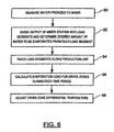
- the steps performed by the control system 40 during a production run are shown in Figure 6.
- calcined gypsum, water and other additives are combined at the mixer station 16 and then extruded from an extruder between upper and lower paper sheets to provide a continuous strip of gypsum board that progresses along the forming belt 18.
- the continuous strip of gypsum board is a future load for the dryer unit 26, and is divided into a series of load segments by the control system 40 in the following manner.
- the quantity of gypsum supplied to the mixer 16 is measured by a weigh belt 86, and the amount of water added to the mixer 16 from various sources is measured by flow meters 88 (step 90), which permits the total amount of water added for a predetermined length of board segment (a "load segment") exiting the extruder to be calculated (the predetermined length of a load segment being equivalent to a production line segment S).
- the total amount of water added for each load segment is used to determine the desired amount of water to be evaporated from each load segment, which is represented herein as a free water val ue e j (where j indicates an arbitrary load segment).
- the free water val ue is the excess water contained in each load segment that is not required for the hydration of the calcined gypsum.
- its free water value e j is stored in the register block 76 of shift register 74 that corresponds to the first segment S 1 of the production line 10 (step 92).
- its free water value e j is continually shifted in synchronization with the movement of the load segment to the next block 76 that corresponds to the next position of the load segment in production line 10, and in this manner the free water value of a particular load segment is tracked through the entire production line 10 (step 94).
- the PLC 60 tracks the speed of the line 10 and advances the shift register 74 in appropriate time periods.
- the boards are cut into predetermined board lengths at knife 20, after which they pass through the wet end transfer station 22 onto dryer transfer system 24.
- the wet end transfer station boards are inspected and rejected boards are removed before they reach dryer transfer system belt 24.
- the wet end transfer station 22 includes a reject gate 23 which removes rejected boards from the line 10 upon receiving a signal from an operator activated switch.
- the load that progresses along the dryer transfer system 24 to and through the dryer 26 is comprised of successive load segments that can include gypsum board or empty spaces where a board or group of boards has been rejected.
- the free water values e j of the load segments formerly occupied by such board or group of boards are set to zero by the dryer control system 40.
- the signal which operates the reject gate 23 also activates a rotary encoder that is connected to the shift register 74, causing the free water values contained in the register blocks 76 corresponding to the production line segments S of line 10 at which the rejected boards are removed to be set to zero as the boards are removed, and the zero values are shifted along the shift register 74 in subsequent time slots, tracking the resulting gap that exists in the line of boards progressing along production line 10.
- the total drying duty and drying duty distribution of the dryer zones 78 and 80 can be continuously calculated and the dryer heat energy controlled to suit that duty (steps 96 and 98).
- a target differential temperature Delta_T between the inlet and outlet of each of the dryer zones 78 and 80 is calculated in successive time periods based on the amount of free water contained in the total load of boards passing through the dryer 26 during each time period. The time period is determined by the length of time it takes a load segment to pass through a single dryer segment DS m .
- the target differential temperature Delta_Tis calculated for each dryer zone in the following manner.
- the free water value of each load segment currently in that dryer zone is multiplied by the coefficient of evaporation k m for the corresponding dryer DS m segment in which that load segment is located for that time period.
- the products resulting from the multiplication of the free water values and co-efficients of evaporations for all the load segments located in the dryer zone during the time period are then summed. This summed value is multiplied by the dryer speed (which is tracked by dryer PLC60) and a value representing drying ratio per dryer zone to provide an energy value.
- the energy value is then converted to a temperature value which is adjusted upward to account for heat losses in the dryer zone.
- the result is a target differential temperature Delta_T, between the inlet and outlet of the dryer zone, and is used as a set point to control the fuel flow to the burner (or other heat input) of the dryer zone, thereby adjusting the dryer zone differential temperature to match the target differential temperature.
- the values representing drying ratio per dryer zone (KZ) are predetermined values (based on the number of drying zones that the dryer has), as are the heat loss adjustment values.
- the conversion factors (C o ) used to convert the calculated energy value into a temperature value for each of the dryer zones are predetermined values which have been derived empirically for each dryer zone.
- the resulting gaps in the board line passing through the dryer unit 26 will be signified by a free water values e j of zero being entered in the calculation of the target differential temperature Delta_T, thus causing the evaporative load of the dryer 26 to be reduced, and the dryer zone differential temperatures to be adjusted accordingly.
- gaps in the board line can also appear at the start and end of a product run, and the present system can adjust the dryer temperature for such gaps accordingly.
- the system described can also adjust for any changes that occur in board formulation for different production runs, thus permitting changes in board formulation to be effected without stopping the production line.
- a moisture reading device can be located at the output end of the second zone 80 to provide moisture readings to the dryer operator interface 50, based on which the temperature of zone 80 can be trimmed by an operator through the dryer operator interface 50.
- the production line segments S 1 have a length less than that of the boards being produced by the line 10.
Landscapes
- Engineering & Computer Science (AREA)
- Structural Engineering (AREA)
- Chemical & Material Sciences (AREA)
- Ceramic Engineering (AREA)
- Mechanical Engineering (AREA)
- Drying Of Solid Materials (AREA)
- Soil Working Implements (AREA)
- Lifting Devices For Agricultural Implements (AREA)
- Flow Control (AREA)
- Transition And Organic Metals Composition Catalysts For Addition Polymerization (AREA)
- Adhesives Or Adhesive Processes (AREA)
- Paper (AREA)
- Compounds Of Alkaline-Earth Elements, Aluminum Or Rare-Earth Metals (AREA)
- Breeding Of Plants And Reproduction By Means Of Culturing (AREA)
- Acyclic And Carbocyclic Compounds In Medicinal Compositions (AREA)
Claims (20)
- Verfahren zum Regeln der Temperatur eines Trockners (26) in einer Gipsplattenproduktionsanlage (10), bei der eine Charge, die eine Reihe von Platten aufweist, dem Trockner (26) zugeführt wird, gekennzeichnet durch die folgenden Schritte:Messen des zum Herstellen der Chargensegmente verwendeten Wasservolumens;Ermitteln, jeweils für jedes der Mehrzahl von Segmenten entlang einer Länge der Charge, einer gewünschten aus jedem der Chargensegmente zu verdunstenden Wassermenge in Abhängigkeit von dem gemessenen zum Herstellen der Chargensegmente verwendeten Wasservolumen;Ermitteln des Energiebetrags, der zum Verdunsten der gewünschten Wassermengen aus den in dem Trockner (26) befindlichen Chargensegmenten während eines bestimmten Zeitintervalls erforderlich ist, undEinstellen der dem Trockner (26) zugeführten Wärmeenergie gemäß dem genannten ermittelten erforderlichen Energiebetrag.
- Verfahren nach Anspruch 1, bei dem der Schritt des Ermittelns einer gewünschten aus jedem Chargensegment zu verdunstenden Wassermenge Folgendes aufweist:Messen eines einer Mischerstation (16) der Produktionsanlage (10) zugeführten Wasservolumens für jedes Chargensegment undBerechnen und Speichern der gewünschten zu verdunstenden Wassermenge für jedes Chargensegment auf der Basis des gemessenen Wasservolumens.
- Verfahren nach Anspruch 2, bei dem der Schritt des Ermittelns einer gewünschten zu verdunstenden Wassermenge für jedes Chargensegment das Einstellen der gewünschten zu verdunstenden Wassermenge für ein Chargensegment auf null aufweist, wenn sich in diesem Chargensegment keine Platte befindet.
- Verfahren nach einem der Ansprüche 1 bis 3, bei dem der Schritt des Ermittelns des zum Verdunsten der gewünschten Wassermengen erforderlichen Energiebetrags Folgendes aufweist:für jedes in dem betreffenden Zeitintervall in einer Trocknerzone (78, 80) des Trockners (26) befindliche Chargensegment Berechnen des Produkts der gewünschten zu verdunstenden Wassermenge und eines Verdunstungskoeffizienten,Summieren der für die Chargensegmente in der Trocknerzone (78, 80) ermittelten Produkte undBerechnen eines Energiewertes durch Multiplizieren der summierten Produkte mit einem Wert, der eine Geschwindigkeit repräsentiert, mit der sich die Chargensegmente durch die Trocknerzone (78, 80) voranbewegen.
- Verfahren nach Anspruch 4, bei dem der mit der gewünschten zu verdunstenden Wassermenge für ein bestimmtes Chargensegment multiplizierte Verdunstungsköeffizient von der Position dieses Chargensegments in der Trocknerzone (78, 80) abhängt.
- Verfahren nach Anspruch 4 oder Anspruch 5, bei dem der genannte Schritt des Ermittelns des zum Verdunsten der gewünschten Wassermengen erforderlichen Energiebetrags das Berechnen einer Soll-Differenztemperatur zwischen einem Einlass und einem Auslass der Trocknerzone (78, 80) durch Umwandeln des Energiewertes in einen Temperaturwert und Einstellen des Temperaturwerts zum Berücksichtigen von Wärmeverlusten in der Trocknerzone (78, 80) aufweist.
- Verfahren nach Anspruch 6, bei dem der Schritt des Einstellens der dem Trockner (26) zugeführten Wärmeenergie das Einstellen einer Differenztemperatur der Trocknerzone (78, 80), so dass sie mit der Soll-Differenztemperatur übereinstimmt, aufweist.
- Verfahren nach einem der.Ansprüche 1 bis 7, bei dem alle Chargensegmente eine einheitliche Länge haben.
- Verfahren nach Anspruch 2, bei dem alle Chargensegmente eine einheitliche Länge haben und das die folgenden Schritte aufweist:(a) Bereitstellen eines Schieberegisters (74) mit einer Mehrzahl von Schieberegisterblöcken (76),(b) Aufteilen der Produktionsanlage in eine Anzahl aufeinanderfolgender Segmente (Si), die jeweils eine der einheitlichen Länge gleiche Länge haben,(c) Assoziieren jedes der Produktionsanlagensegmente (Si) mit einem eindeutigen Block (76) des Schieberegisters (74) und(d) Verfolgen der gewünschten aus jedem der Chargensegmente, die sich entlang der Produktionsanlage voranbewegen, zu verdunstenden Wassermenge durch aufeinanderfolgende Zeiträume, indem für jedes Chargensegment während jedes Zeitintervalls die gewünschte zu verdunstende Wassermenge für das Chargensegment in einem Schieberegisterblock (76) gespeichert wird, der mit dem Produktionsanlagensegment (Si), durch das das Chargensegment während des Zeitintervalls passiert, assoziiert ist.
- Verfahren nach Anspruch 9, bei dem der Schritt des Berechnens und Speicherns der gewünschten zu verdunstenden Wassermenge das Einstellen der gewünschten aus einem Chargensegment zu verdunstenden Wassermenge auf null aufweist, wenn eine dieses Chargensegment einnehmende Platte aus der Produktionsanlage entfernt wird.
- Verfahren nach Anspruch 9 und Anspruch 10 mit den folgenden Schritten:Bereitstellen eines weiteren Registers (82) mit einer Mehrzahl von Registerblöcken (84);Unterteilen einer Trocknerzone des Trockners in X aufeinanderfolgende Trocknersegmente (DSm), die jeweils eine Länge gleich der einheitlichen Länge haben;Assoziieren jedes der Trocknersegmente (DSm) mit einem eindeutigen Block (84) des weiteren Registers (82) undBereitstellen und Speichern eines einen Verdunstungskoeffizienten km repräsentierenden Wertes für jedes der Trocknersegmente (DSm) in dem mit diesem Trocknersegment assoziierten Registerblock (84),wobei der Schritt des Ermittelns des Energiebetrags Folgendes aufweist: das Ermitteln einer Geschwindigkeit, mit der sich die Chargensegmente durch den Trockner (26) voranbewegen, und das Berechnen eines Energiegesamtbetrags durch Berechnen eines Produkts der gewünschten zu verdunstenden Wassermenge und des Verdunstungskoeffizienten für das Chargensegment (DSm), durch das das Chargensegment in dem betreffenden Zeitintervall passiert, für jedes in dem betreffenden Zeitintervall in der Trocknerzone (78, 80) befindliche Chargensegment, Summieren der für die in dem betreffenden Zeitintervall in der Trocknerzone (78, 80) befindlichen Chargensegmente (DSm) berechneten Produkte und Multiplizieren der summierten Produkte mit einem Wert, der eine Geschwindigkeit repräsentiert, mit der sich die Chargensegmente durch die Trocknerzone (78, 80) voranbewegen, und einem Wert, der ein gewünschtes Trocknungsverhältnis für die Trocknerzone repräsentiert.
- Verfahren nach Anspruch 11, bei dem der Energiegesamtbetrag in eine Soll-Differenztemperatur zwischen einem Einlass und einem Auslass der Trocknerzone (78, 80) umgewandelt und zum Kompensieren von Wärmeverlusten aus der Trocknerzone (78, 80) angepasst wird und der Schritt des Einstellens der dem Trockner (26) zugeführten Wärmeenergie das Einstellen der Differenztemperatur der Trocknerzone (78, 80), so dass sie mit der Soll-Differenztemperatur übereinstimmt, aufweist.
- Gipsplattentrocknungsvorrichtung für eine Gipsplattenproduktionsanlage, umfassend:einen Trockner (26) mit einer Wärmeenergiequelle (79, 81) zum Zuführen von Wärmeenergie zu dem Trockner undein Transportsystem (24) zum Transferieren einer eine Reihe von Gipsplatten umfassenden Charge zu dem und durch den Trockner (26); gekennzeichnet durcheine Einrichtung zum Messen des zum Herstellen der Chargensegmente verwendeten Wasservolumens undein Steuersystem (40) für den Trockner, wobei das Steuersystem Folgendes aufweist:(a) eine Ermittlungseinrichtung (92) zum Ermitteln, jeweils für jedes der Mehrzahl von Segmenten (S1, S2 ...) entlang der Länge der Charge, einer gewünschten aus jedem der Chargensegmente zu verdunstenden Wassermenge in Abhängigkeit von dem gemessenen zum Herstellen der Chargensegmente verwendeten Wasservolumen;(b) eine auf die Ermittlungseinrichtung (92) reagierenden Recheneinrichtung (96) zum Ermitteln eines zum Verdunsten der gewünschten Wassermengen aus allen während eines bestimmten Zeitintervalls in dem Trockner (26) befindlichen Chargensegmenten erforderlichen Energiebetrags und(c) eine auf die Recheneinrichtung (96) reagierende und funktionell mit der Wärmeenergiequelle (79, 81) verbundene Einstelleinrichtung (98) zum Einstellen der dem Trockner (26) zugeführten Wärmeenergie gemäß dem ermittelten Energiebetrag.
- Trocknungsvorrichtung nach Anspruch 13, bei der die Ermittlungseinrichtung (92) eine Messeinrichtung (90) zum Messen der einer Mischerstation (16) der Produktionsanlage zum Produzieren jedes Chargensegments zugeführten Wassermenge und eine Einrichtung (96) zum Berechnen und Speichern der gewünschten zu verdunstenden Wassermenge für jedes Chargensegment auf der Basis des gemessenen Wertes aufweist.
- Trocknungsvorrichtung nach Anspruch 14, bei der die Rechen- und Speichereinrichtung (96) konfiguriert ist, um in einander folgenden Zeitintervallen die Position und die gewünschte zu verdunstende Wassermenge für jedes Chargensegment zu verfolgen, und Folgendes aufweist:ein Schieberegister (74) mit einer Mehrzahl von Schieberegisterblöcken (76);eine Einrichtung zum fiktiven Aufteilen der Produktionsanlage in eine Anzahl aufeinanderfolgender Segmente, die jeweils eine Länge haben, die ungefähr gleich einer Länge eines Chargensegments ist;eine Einrichtung zum Assoziieren jedes Produktionsanlagensegmentes mit einem eindeutigen Schieberegisterblock undeine Einrichtung zum Speichern der gewünschten aus jedem Chargensegment zu verdunstenden Wassermenge in dem Schieberegisterblock, der mit dem Produktionsanlagensegment assoziiert ist, das jedes Chargensegment während jedes Zeitintervalls durchläuft.
- Trocknungsvorrichtung nach einem der Ansprüche 13 bis 15, bei der der Trockner (26) eine Mehrzahl von Trockenzonen (78, 80) aufweist, die jeweils eine unabhängige Wärmeenergiequelle (79, 81) haben, die von der genannten Einstelleinrichtung gesteuert wird, und das Steuersystem eine Einrichtung zum Ermitteln einer Trocknergeschwindigkeit, mit der sich die Chargensegmente durch den Trockner (26) voranbewegen, und zum Übertragen der Trocknergeschwindigkeit zu der Recheneinrichtung aufweist, wobei die Recheneinrichtung (96) für Folgendes für jede Trockenzone (78, 80) konfiguriert ist:zum Berechnen des Produkts der gewünschten zu verdunstenden Wassermenge für das Chargensegment und eines Verdunstungskoeffizienten, das von der Position des Chargensegments in der Trocknerzone (78, 80) abhängt, für jedes während des Zeitintervalls in der Trocknerzone (78, 80) befindliche Chargensegment,zum Summieren der für die Chargensegmente in der Trocknerzone (78, 80) erhaltenen Produkte undBerechnen eines Energiewertes durch Multiplizieren der summierten Produkte für die Trocknerzone (78, 80) mit der Trocknergeschwindigkeit und einem vorbestimmten Wert, der ein gewünschtes Trocknungsverhältnis für die Trocknerzone (78, 80) repräsentiert.
- Trocknungsvorrichtung nach einem der Ansprüche 13 bis 16, bei der die Ermittlungseinrichtung (92) konfiguriert ist, um die gewünschte zu verdunstende Wassermenge für ein bestimmtes Chargensegment auf null zu setzen, wenn sich in dem Chargensegment keine Platte befindet.
- Trocknungsvorrichtung nach einem der Ansprüche 13 bis 17, bei der die Ermittlungseinrichtung (92) und die Einstellungseinrichtung (98) jeweils ein programmierbares logisches Steuergerät (58, 60) aufweist und die Recheneinrichtung wenigstens ein vorprogrammiertes Computersystem (42) aufweist.
- Trocknersteuersystem (40) zum Steuern des Betriebs eines Trockners (26) in einer Gipsplattenproduktionsanlage (10), in der eine Charge, die eine Reihe von Gipsplatten aufweist, dem Trockner (26) zugeführt wird, gekennzeichnet durch:eine Ermittlungseinrichtung (92) zum Messen der einer Mischerstation (16) der Produktionsanlage (10) zugeführten Wassermenge und zum Ermitteln und Speichern, für jedes einer Reihe von einander folgenden Chargensegmenten (s1, s2 ...) einheitlicher Länge, einer gewünschten aus jedem der einander folgenden Chargensegmente zu verdunstenden Wassermenge auf der Basis der gemessenen Wassermenge;eine auf die Ermittlungseinrichtung reagierende Recheneinrichtung (96) zum Ermitteln einer Verdunstungslast des Trockners (26) auf der Basis der gewünschten aus allen zu einem bestimmten Zeitpunkt in dem Trockner (26) befindlichen Chargensegmenten zu verdunstenden Wassermengen undeine auf die Recheneinrichtung (96) reagierende Einstelleinrichtung (98) zum Steuern eines Heizelements (79, 81) des Trockners (26) zum Einstellen von dem Trockner (26) zugeführter Wärmeenergie gemäß der ermittelten Verdunstungslast.
- Gipsplattenproduktionsanlage (10), umfassend ein Trocknersteuersystem nach Anspruch 19.
Applications Claiming Priority (2)
| Application Number | Priority Date | Filing Date | Title |
|---|---|---|---|
| CA2259743 | 1999-01-18 | ||
| CA002259743A CA2259743C (en) | 1999-01-18 | 1999-01-18 | Dryer control system |
Publications (3)
| Publication Number | Publication Date |
|---|---|
| EP1020267A1 EP1020267A1 (de) | 2000-07-19 |
| EP1020267B1 EP1020267B1 (de) | 2003-12-10 |
| EP1020267B2 true EP1020267B2 (de) | 2006-10-11 |
Family
ID=4163210
Family Applications (1)
| Application Number | Title | Priority Date | Filing Date |
|---|---|---|---|
| EP00300338A Expired - Lifetime EP1020267B2 (de) | 1999-01-18 | 2000-01-18 | Steuerungsvorrichtung für einen Trockner in einer Anlage zur Herstellung von Gipsbauplatten |
Country Status (10)
| Country | Link |
|---|---|
| US (1) | US6418638B1 (de) |
| EP (1) | EP1020267B2 (de) |
| AT (1) | ATE255990T1 (de) |
| AU (1) | AU771040B2 (de) |
| CA (1) | CA2259743C (de) |
| DE (1) | DE60007006T3 (de) |
| DK (1) | DK1020267T4 (de) |
| ES (1) | ES2211447T5 (de) |
| NO (1) | NO328337B1 (de) |
| PT (1) | PT1020267E (de) |
Families Citing this family (8)
| Publication number | Priority date | Publication date | Assignee | Title |
|---|---|---|---|---|
| AT405560B (de) | 1997-06-18 | 1999-09-27 | Kaindl M | Anordnung mit bauteilen und bauteile |
| US20040052297A1 (en) * | 2002-05-16 | 2004-03-18 | Raytek | Thermal monitoring system |
| MX354701B (es) * | 2012-10-18 | 2018-03-16 | Yoshino Gypsum Co | Método para detectar vacíos en tabla de construcción a base de yeso y método para producir tabla de construcción a base de yeso. |
| US9983574B2 (en) | 2013-09-30 | 2018-05-29 | United States Gypsum Company | Systems and methods for controlling a conveyor system during product changeovers |
| CN104536366A (zh) * | 2014-12-12 | 2015-04-22 | 东北林业大学 | 基于plc的集成化全自动小型干燥系统 |
| CN113551513B (zh) * | 2021-07-13 | 2022-08-26 | 北新建材(苏州)有限公司 | 一种石膏板干燥机的控温容错系统及方法 |
| US12472660B2 (en) * | 2023-03-03 | 2025-11-18 | Logistics and Supply Chain MultiTech R&D Centre Limited | Automated concrete cube processing system |
| CN120722823B (zh) * | 2025-08-29 | 2026-01-09 | 泰山石膏(四川)有限公司 | 一种纸面石膏板控制方法、系统、设备及介质 |
Citations (1)
| Publication number | Priority date | Publication date | Assignee | Title |
|---|---|---|---|---|
| DE2721965A1 (de) † | 1977-05-14 | 1978-11-23 | Babcock Bsh Ag | Verfahren und vorrichtung zur ueberwachung und steuerung des trockenverlaufs bei der trocknung von furnieren und aehnlichem gut |
Family Cites Families (16)
| Publication number | Priority date | Publication date | Assignee | Title |
|---|---|---|---|---|
| US4113554A (en) * | 1976-02-03 | 1978-09-12 | Rogers Corporation | Method of manufacturing insulating board |
| FR2484899A1 (fr) * | 1980-06-18 | 1981-12-24 | Saint Gobain Isover | Procede et dispositif d'elimination de l'eau excedentaire d'un melange de platre et d'eau, et produits obtenus |
| US4498864A (en) * | 1982-12-10 | 1985-02-12 | Techmark Corporation | Method and apparatus for uniformly drying moving webs |
| FI80100C (fi) | 1986-12-18 | 1990-04-10 | Valmet Oy | Foerfarande vid styrning och/eller oevervakning av en belaeggningsprocess av en bana. |
| US5323546A (en) * | 1989-02-10 | 1994-06-28 | Eastman Kodak Company | Method of drying photographic materials |
| US5010659A (en) * | 1989-09-08 | 1991-04-30 | W. R. Grace & Co.-Conn. | Infrared drying system |
| US5632848A (en) * | 1989-10-12 | 1997-05-27 | Georgia-Pacific Corporation | Continuous processing equipment for making fiberboard |
| US5377428A (en) * | 1993-09-14 | 1995-01-03 | James River Corporation Of Virginia | Temperature sensing dryer profile control |
| EP0738183A4 (de) * | 1993-12-13 | 1997-08-06 | Henkel Corp | Schaumbildende zusammensetzung und verfahren |
| US5465504A (en) * | 1994-04-08 | 1995-11-14 | James River Paper Company, Inc. | System for modifying the moisture profile of a paper web |
| US5603168A (en) | 1994-11-30 | 1997-02-18 | The Coe Manufacturing Company | Method and apparatus for controlling a dryer |
| DE4447270A1 (de) * | 1994-12-30 | 1996-07-04 | Bosch Siemens Hausgeraete | Verfahren zum Steuern von Trockenvorgängen in Haushalt-Wäschetrocknern |
| US5659972A (en) * | 1995-10-06 | 1997-08-26 | Avery Dennison Corporation | Apparatus and method for drying or curing web materials and coatings |
| US5997779A (en) * | 1996-12-18 | 1999-12-07 | Aki Dryer Manufacturer, Inc. | Temperature monitor for gypsum board manufacturing |
| US6045730A (en) * | 1996-12-18 | 2000-04-04 | Aki Dryer Manufactures, Inc. | Process monitor for gypsum board manufacturing |
| US6169848B1 (en) * | 2000-01-06 | 2001-01-02 | Impact Systems, Inc. | Cross-direction dryer for a machine producing sheet material moving in a machine direction having both gas powered and electric heating portions |
-
1999
- 1999-01-18 CA CA002259743A patent/CA2259743C/en not_active Expired - Lifetime
-
2000
- 2000-01-14 US US09/483,789 patent/US6418638B1/en not_active Expired - Lifetime
- 2000-01-18 NO NO20000252A patent/NO328337B1/no not_active IP Right Cessation
- 2000-01-18 PT PT00300338T patent/PT1020267E/pt unknown
- 2000-01-18 ES ES00300338T patent/ES2211447T5/es not_active Expired - Lifetime
- 2000-01-18 AT AT00300338T patent/ATE255990T1/de active
- 2000-01-18 EP EP00300338A patent/EP1020267B2/de not_active Expired - Lifetime
- 2000-01-18 DK DK00300338T patent/DK1020267T4/da active
- 2000-01-18 DE DE60007006T patent/DE60007006T3/de not_active Expired - Lifetime
- 2000-01-18 AU AU12461/00A patent/AU771040B2/en not_active Ceased
Patent Citations (1)
| Publication number | Priority date | Publication date | Assignee | Title |
|---|---|---|---|---|
| DE2721965A1 (de) † | 1977-05-14 | 1978-11-23 | Babcock Bsh Ag | Verfahren und vorrichtung zur ueberwachung und steuerung des trockenverlaufs bei der trocknung von furnieren und aehnlichem gut |
Also Published As
| Publication number | Publication date |
|---|---|
| DK1020267T3 (da) | 2004-04-13 |
| DK1020267T4 (da) | 2007-01-29 |
| EP1020267A1 (de) | 2000-07-19 |
| ES2211447T5 (es) | 2007-05-01 |
| DE60007006T2 (de) | 2004-09-16 |
| US6418638B1 (en) | 2002-07-16 |
| EP1020267B1 (de) | 2003-12-10 |
| AU771040B2 (en) | 2004-03-11 |
| ES2211447T3 (es) | 2004-07-16 |
| DE60007006D1 (de) | 2004-01-22 |
| NO328337B1 (no) | 2010-02-01 |
| CA2259743A1 (en) | 2000-07-18 |
| DE60007006T3 (de) | 2007-05-16 |
| PT1020267E (pt) | 2004-04-30 |
| NO20000252L (no) | 2000-07-19 |
| NO20000252D0 (no) | 2000-01-18 |
| ATE255990T1 (de) | 2003-12-15 |
| AU1246100A (en) | 2000-07-20 |
| CA2259743C (en) | 2006-06-13 |
Similar Documents
| Publication | Publication Date | Title |
|---|---|---|
| EP1020267B1 (de) | Steuerungsvorrichtung für einen Trockner in einer Anlage zur Herstellung von Gipsbauplatten | |
| US4626389A (en) | Installation for the continuous production of materials using exothermically hardening binders and method | |
| EP0266403B1 (de) | Verfahren zum steuern einer futtermischanlage, sowie futtermischanlage zur durchführung des verfahrens | |
| US4955216A (en) | Method and apparatus for automatically adjusting soluble oil flow rates to control metallurgical properties of continuously rolled rod | |
| WO2000066963A1 (de) | Verfahren und vorrichtung zur optimierung der prozessführung sowie prozessüberwachung in einer anlage zur herstellung von teigwaren | |
| US4849234A (en) | Method of machining doughy material | |
| CN100458604C (zh) | 物料平衡智能控制系统 | |
| EP0146826B1 (de) | Verfahren der Temperaturregelung einer Trocknungsanlage | |
| DE2725781C2 (de) | Verfahren zur Verarbeitung von Lebensmitteln, insbesondere von Fleisch- und Wurstwaren und Einrichtung zur Steuerung des Verfahrens | |
| AU2023359628A1 (en) | Method and system for measuring the setting time of a gypsum board | |
| EP4133345B1 (de) | Verfahren zur dynamischen produktionsplanung bei strangguss anlagen | |
| ITMI20001237A1 (it) | Procedimento e dispositivo per ottimizzare la conduzione di processo,nonche' sorveglianza di processo in un impianto per produrre cioccolat | |
| JP4150434B2 (ja) | アスファルトプラントのバーナ燃焼制御方法 | |
| EP0422833A2 (de) | Steuervorrichtung und Verfahren zur Herstellung von Gipsplatten | |
| US20260133072A1 (en) | Method and system for measuring the setting time of a gypsum board | |
| WO2024161243A1 (en) | Plant for manufacturing articles made of stone, stone-like or ceramic agglomerate material and method for adjusting and controlling the process for manufacturing such articles | |
| SU1516364A2 (ru) | Устройство дл управлени процессом изготовлени бетонных и железобетонных изделий | |
| SU1099204A1 (ru) | Система автоматического управлени процессом обжига керамических плиток в щелевой печи | |
| SU659394A1 (ru) | Устройство дл управлени процессом приготовлени бетонной смеси в бетоносмесител х непрерывного действи с пароразогревом | |
| JPH10258410A (ja) | 押出機の制御方法及び押出機の制御装置 | |
| Liang et al. | Profile control of plastic sheet in an industrial polymer processing process | |
| Miller | Automation in Metal Processing: A Review | |
| JPH05219873A (ja) | オーブン制御装置 | |
| DD217647A1 (de) | Verfahren zur kontinuierlichen erfassung und regelung der dicke bzw. masse von halbfabrikaten und fertigteilen im laufenden produktionsprozess | |
| JPH06299259A (ja) | 焼結鉱の焼成方法 |
Legal Events
| Date | Code | Title | Description |
|---|---|---|---|
| PUAI | Public reference made under article 153(3) epc to a published international application that has entered the european phase |
Free format text: ORIGINAL CODE: 0009012 |
|
| AK | Designated contracting states |
Kind code of ref document: A1 Designated state(s): AT BE CH CY DE DK ES FI FR GB GR IE IT LI LU MC NL PT SE |
|
| AX | Request for extension of the european patent |
Free format text: AL;LT;LV;MK;RO;SI |
|
| 17P | Request for examination filed |
Effective date: 20010117 |
|
| AKX | Designation fees paid |
Free format text: AT BE CH CY DE DK ES FI FR GB GR IE IT LI LU MC NL PT SE |
|
| 17Q | First examination report despatched |
Effective date: 20021206 |
|
| GRAH | Despatch of communication of intention to grant a patent |
Free format text: ORIGINAL CODE: EPIDOS IGRA |
|
| RAP1 | Party data changed (applicant data changed or rights of an application transferred) |
Owner name: BPB CANADA INC. |
|
| GRAS | Grant fee paid |
Free format text: ORIGINAL CODE: EPIDOSNIGR3 |
|
| GRAA | (expected) grant |
Free format text: ORIGINAL CODE: 0009210 |
|
| AK | Designated contracting states |
Kind code of ref document: B1 Designated state(s): AT BE CH CY DE DK ES FI FR GB GR IE IT LI LU MC NL PT SE |
|
| REG | Reference to a national code |
Ref country code: GB Ref legal event code: FG4D |
|
| REG | Reference to a national code |
Ref country code: CH Ref legal event code: EP |
|
| REG | Reference to a national code |
Ref country code: IE Ref legal event code: FG4D |
|
| REF | Corresponds to: |
Ref document number: 60007006 Country of ref document: DE Date of ref document: 20040122 Kind code of ref document: P |
|
| REG | Reference to a national code |
Ref country code: SE Ref legal event code: TRGR |
|
| REG | Reference to a national code |
Ref country code: DK Ref legal event code: T3 |
|
| REG | Reference to a national code |
Ref country code: CH Ref legal event code: NV Representative=s name: KIRKER & CIE SA |
|
| REG | Reference to a national code |
Ref country code: GR Ref legal event code: EP Ref document number: 20040400811 Country of ref document: GR |
|
| REG | Reference to a national code |
Ref country code: PT Ref legal event code: SC4A Free format text: AVAILABILITY OF NATIONAL TRANSLATION Effective date: 20040310 |
|
| REG | Reference to a national code |
Ref country code: ES Ref legal event code: FG2A Ref document number: 2211447 Country of ref document: ES Kind code of ref document: T3 |
|
| PLBQ | Unpublished change to opponent data |
Free format text: ORIGINAL CODE: EPIDOS OPPO |
|
| PLBI | Opposition filed |
Free format text: ORIGINAL CODE: 0009260 |
|
| ET | Fr: translation filed | ||
| PLAX | Notice of opposition and request to file observation + time limit sent |
Free format text: ORIGINAL CODE: EPIDOSNOBS2 |
|
| 26 | Opposition filed |
Opponent name: GRENZEBACH BSH GMBH Effective date: 20040910 |
|
| NLR1 | Nl: opposition has been filed with the epo |
Opponent name: GRENZEBACH BSH GMBH |
|
| PLAX | Notice of opposition and request to file observation + time limit sent |
Free format text: ORIGINAL CODE: EPIDOSNOBS2 |
|
| PLAB | Opposition data, opponent's data or that of the opponent's representative modified |
Free format text: ORIGINAL CODE: 0009299OPPO |
|
| PLAQ | Examination of admissibility of opposition: information related to despatch of communication + time limit deleted |
Free format text: ORIGINAL CODE: EPIDOSDOPE2 |
|
| PLAR | Examination of admissibility of opposition: information related to receipt of reply deleted |
Free format text: ORIGINAL CODE: EPIDOSDOPE4 |
|
| PLBB | Reply of patent proprietor to notice(s) of opposition received |
Free format text: ORIGINAL CODE: EPIDOSNOBS3 |
|
| PLBQ | Unpublished change to opponent data |
Free format text: ORIGINAL CODE: EPIDOS OPPO |
|
| R26 | Opposition filed (corrected) |
Opponent name: GRENZEBACH BSH GMBH Effective date: 20040910 |
|
| NLR1 | Nl: opposition has been filed with the epo |
Opponent name: GRENZEBACH BSH GMBH |
|
| PLBP | Opposition withdrawn |
Free format text: ORIGINAL CODE: 0009264 |
|
| PUAH | Patent maintained in amended form |
Free format text: ORIGINAL CODE: 0009272 |
|
| STAA | Information on the status of an ep patent application or granted ep patent |
Free format text: STATUS: PATENT MAINTAINED AS AMENDED |
|
| 27A | Patent maintained in amended form |
Effective date: 20061011 |
|
| AK | Designated contracting states |
Kind code of ref document: B2 Designated state(s): AT BE CH CY DE DK ES FI FR GB GR IE IT LI LU MC NL PT SE |
|
| REG | Reference to a national code |
Ref country code: CH Ref legal event code: AEN Free format text: AUFRECHTERHALTUNG DES PATENTES IN GEAENDERTER FORM |
|
| NLR2 | Nl: decision of opposition |
Effective date: 20061011 |
|
| REG | Reference to a national code |
Ref country code: SE Ref legal event code: RPEO |
|
| REG | Reference to a national code |
Ref country code: GR Ref legal event code: EP Ref document number: 20060404365 Country of ref document: GR |
|
| REG | Reference to a national code |
Ref country code: DK Ref legal event code: T4 |
|
| NLR3 | Nl: receipt of modified translations in the netherlands language after an opposition procedure | ||
| REG | Reference to a national code |
Ref country code: ES Ref legal event code: DC2A Date of ref document: 20061205 Kind code of ref document: T5 |
|
| ET3 | Fr: translation filed ** decision concerning opposition | ||
| REG | Reference to a national code |
Ref country code: FR Ref legal event code: PLFP Year of fee payment: 17 |
|
| REG | Reference to a national code |
Ref country code: FR Ref legal event code: PLFP Year of fee payment: 18 |
|
| PGFP | Annual fee paid to national office [announced via postgrant information from national office to epo] |
Ref country code: CY Payment date: 20161219 Year of fee payment: 18 |
|
| REG | Reference to a national code |
Ref country code: FR Ref legal event code: PLFP Year of fee payment: 19 |
|
| PG25 | Lapsed in a contracting state [announced via postgrant information from national office to epo] |
Ref country code: CY Free format text: LAPSE BECAUSE OF NON-PAYMENT OF DUE FEES Effective date: 20180118 |
|
| PGFP | Annual fee paid to national office [announced via postgrant information from national office to epo] |
Ref country code: GR Payment date: 20181212 Year of fee payment: 20 Ref country code: MC Payment date: 20181228 Year of fee payment: 20 |
|
| PGFP | Annual fee paid to national office [announced via postgrant information from national office to epo] |
Ref country code: FR Payment date: 20181213 Year of fee payment: 20 Ref country code: BE Payment date: 20181217 Year of fee payment: 20 |
|
| PGFP | Annual fee paid to national office [announced via postgrant information from national office to epo] |
Ref country code: LU Payment date: 20190108 Year of fee payment: 20 |
|
| PGFP | Annual fee paid to national office [announced via postgrant information from national office to epo] |
Ref country code: DE Payment date: 20190108 Year of fee payment: 20 Ref country code: IE Payment date: 20190109 Year of fee payment: 20 Ref country code: FI Payment date: 20190109 Year of fee payment: 20 Ref country code: CH Payment date: 20190115 Year of fee payment: 20 Ref country code: ES Payment date: 20190201 Year of fee payment: 20 Ref country code: IT Payment date: 20190121 Year of fee payment: 20 Ref country code: GB Payment date: 20190116 Year of fee payment: 20 Ref country code: NL Payment date: 20190116 Year of fee payment: 20 |
|
| PGFP | Annual fee paid to national office [announced via postgrant information from national office to epo] |
Ref country code: SE Payment date: 20190110 Year of fee payment: 20 Ref country code: AT Payment date: 20181221 Year of fee payment: 20 Ref country code: DK Payment date: 20190110 Year of fee payment: 20 |
|
| PGFP | Annual fee paid to national office [announced via postgrant information from national office to epo] |
Ref country code: PT Payment date: 20190118 Year of fee payment: 20 |
|
| REG | Reference to a national code |
Ref country code: DE Ref legal event code: R071 Ref document number: 60007006 Country of ref document: DE |
|
| REG | Reference to a national code |
Ref country code: DK Ref legal event code: EUP Effective date: 20200118 |
|
| REG | Reference to a national code |
Ref country code: NL Ref legal event code: MK Effective date: 20200117 |
|
| REG | Reference to a national code |
Ref country code: GB Ref legal event code: PE20 Expiry date: 20200117 |
|
| REG | Reference to a national code |
Ref country code: FI Ref legal event code: MAE |
|
| REG | Reference to a national code |
Ref country code: SE Ref legal event code: EUG |
|
| REG | Reference to a national code |
Ref country code: IE Ref legal event code: MK9A |
|
| REG | Reference to a national code |
Ref country code: AT Ref legal event code: MK07 Ref document number: 255990 Country of ref document: AT Kind code of ref document: T Effective date: 20200118 |
|
| REG | Reference to a national code |
Ref country code: BE Ref legal event code: MK Effective date: 20200118 |
|
| PG25 | Lapsed in a contracting state [announced via postgrant information from national office to epo] |
Ref country code: IE Free format text: LAPSE BECAUSE OF EXPIRATION OF PROTECTION Effective date: 20200118 Ref country code: PT Free format text: LAPSE BECAUSE OF EXPIRATION OF PROTECTION Effective date: 20200130 Ref country code: GB Free format text: LAPSE BECAUSE OF EXPIRATION OF PROTECTION Effective date: 20200117 |
|
| REG | Reference to a national code |
Ref country code: ES Ref legal event code: FD2A Effective date: 20200805 |
|
| PG25 | Lapsed in a contracting state [announced via postgrant information from national office to epo] |
Ref country code: ES Free format text: LAPSE BECAUSE OF EXPIRATION OF PROTECTION Effective date: 20200119 |