EP1019990B1 - Verfahren zum herstellen eines kommutatorringes für einen kommutator sowie danach hergestellter kommutator - Google Patents
Verfahren zum herstellen eines kommutatorringes für einen kommutator sowie danach hergestellter kommutator Download PDFInfo
- Publication number
- EP1019990B1 EP1019990B1 EP98928121A EP98928121A EP1019990B1 EP 1019990 B1 EP1019990 B1 EP 1019990B1 EP 98928121 A EP98928121 A EP 98928121A EP 98928121 A EP98928121 A EP 98928121A EP 1019990 B1 EP1019990 B1 EP 1019990B1
- Authority
- EP
- European Patent Office
- Prior art keywords
- segments
- slots
- commutator
- gouged
- dovetail
- Prior art date
- Legal status (The legal status is an assumption and is not a legal conclusion. Google has not performed a legal analysis and makes no representation as to the accuracy of the status listed.)
- Expired - Lifetime
Links
- 238000000034 method Methods 0.000 title claims description 13
- 239000000463 material Substances 0.000 claims description 3
- 239000012212 insulator Substances 0.000 claims 2
- 241000446313 Lamella Species 0.000 description 10
- 238000004519 manufacturing process Methods 0.000 description 8
- 238000004049 embossing Methods 0.000 description 5
- 238000004873 anchoring Methods 0.000 description 4
- 239000011810 insulating material Substances 0.000 description 4
- 238000009413 insulation Methods 0.000 description 2
- 238000000465 moulding Methods 0.000 description 2
- QFLWZFQWSBQYPS-AWRAUJHKSA-N (3S)-3-[[(2S)-2-[[(2S)-2-[5-[(3aS,6aR)-2-oxo-1,3,3a,4,6,6a-hexahydrothieno[3,4-d]imidazol-4-yl]pentanoylamino]-3-methylbutanoyl]amino]-3-(4-hydroxyphenyl)propanoyl]amino]-4-[1-bis(4-chlorophenoxy)phosphorylbutylamino]-4-oxobutanoic acid Chemical compound CCCC(NC(=O)[C@H](CC(O)=O)NC(=O)[C@H](Cc1ccc(O)cc1)NC(=O)[C@@H](NC(=O)CCCCC1SC[C@@H]2NC(=O)N[C@H]12)C(C)C)P(=O)(Oc1ccc(Cl)cc1)Oc1ccc(Cl)cc1 QFLWZFQWSBQYPS-AWRAUJHKSA-N 0.000 description 1
- RYGMFSIKBFXOCR-UHFFFAOYSA-N Copper Chemical compound [Cu] RYGMFSIKBFXOCR-UHFFFAOYSA-N 0.000 description 1
- 230000004323 axial length Effects 0.000 description 1
- 229910052802 copper Inorganic materials 0.000 description 1
- 239000010949 copper Substances 0.000 description 1
- 238000006073 displacement reaction Methods 0.000 description 1
- 239000002184 metal Substances 0.000 description 1
- 229910052751 metal Inorganic materials 0.000 description 1
- 238000005457 optimization Methods 0.000 description 1
- 238000005096 rolling process Methods 0.000 description 1
- 238000010008 shearing Methods 0.000 description 1
- 230000032258 transport Effects 0.000 description 1
- 238000004804 winding Methods 0.000 description 1
Images


Classifications
-
- H—ELECTRICITY
- H02—GENERATION; CONVERSION OR DISTRIBUTION OF ELECTRIC POWER
- H02K—DYNAMO-ELECTRIC MACHINES
- H02K13/00—Structural associations of current collectors with motors or generators, e.g. brush mounting plates or connections to windings; Disposition of current collectors in motors or generators; Arrangements for improving commutation
-
- H—ELECTRICITY
- H01—ELECTRIC ELEMENTS
- H01R—ELECTRICALLY-CONDUCTIVE CONNECTIONS; STRUCTURAL ASSOCIATIONS OF A PLURALITY OF MUTUALLY-INSULATED ELECTRICAL CONNECTING ELEMENTS; COUPLING DEVICES; CURRENT COLLECTORS
- H01R43/00—Apparatus or processes specially adapted for manufacturing, assembling, maintaining, or repairing of line connectors or current collectors or for joining electric conductors
- H01R43/06—Manufacture of commutators
- H01R43/08—Manufacture of commutators in which segments are not separated until after assembly
-
- Y—GENERAL TAGGING OF NEW TECHNOLOGICAL DEVELOPMENTS; GENERAL TAGGING OF CROSS-SECTIONAL TECHNOLOGIES SPANNING OVER SEVERAL SECTIONS OF THE IPC; TECHNICAL SUBJECTS COVERED BY FORMER USPC CROSS-REFERENCE ART COLLECTIONS [XRACs] AND DIGESTS
- Y10—TECHNICAL SUBJECTS COVERED BY FORMER USPC
- Y10T—TECHNICAL SUBJECTS COVERED BY FORMER US CLASSIFICATION
- Y10T29/00—Metal working
- Y10T29/49—Method of mechanical manufacture
- Y10T29/49002—Electrical device making
- Y10T29/49009—Dynamoelectric machine
-
- Y—GENERAL TAGGING OF NEW TECHNOLOGICAL DEVELOPMENTS; GENERAL TAGGING OF CROSS-SECTIONAL TECHNOLOGIES SPANNING OVER SEVERAL SECTIONS OF THE IPC; TECHNICAL SUBJECTS COVERED BY FORMER USPC CROSS-REFERENCE ART COLLECTIONS [XRACs] AND DIGESTS
- Y10—TECHNICAL SUBJECTS COVERED BY FORMER USPC
- Y10T—TECHNICAL SUBJECTS COVERED BY FORMER US CLASSIFICATION
- Y10T29/00—Metal working
- Y10T29/49—Method of mechanical manufacture
- Y10T29/49002—Electrical device making
- Y10T29/49009—Dynamoelectric machine
- Y10T29/49011—Commutator or slip ring assembly
-
- Y—GENERAL TAGGING OF NEW TECHNOLOGICAL DEVELOPMENTS; GENERAL TAGGING OF CROSS-SECTIONAL TECHNOLOGIES SPANNING OVER SEVERAL SECTIONS OF THE IPC; TECHNICAL SUBJECTS COVERED BY FORMER USPC CROSS-REFERENCE ART COLLECTIONS [XRACs] AND DIGESTS
- Y10—TECHNICAL SUBJECTS COVERED BY FORMER USPC
- Y10T—TECHNICAL SUBJECTS COVERED BY FORMER US CLASSIFICATION
- Y10T29/00—Metal working
- Y10T29/49—Method of mechanical manufacture
- Y10T29/49002—Electrical device making
- Y10T29/49009—Dynamoelectric machine
- Y10T29/49012—Rotor
Definitions
- the invention is based on a method for manufacturing a commutator ring for a commutator of the type of the main claim. It is known to make commutator rings a previously embossed tape material for so-called Manufacture rolling commutators. Here is a if necessary, profiled endless belt, the width of which corresponds to the later axial length of the commutator, transverse to Direction of movement of the belt using a molding tool Provide grooves so that only connected via webs Slats are created. According to the number of slats one Commutator rings will have a corresponding number of lamellae cut off from the continuous, now formed band and closed to the commutator ring. To stabilize the Commutator rings and insulation of the individual lamellae the commutator ring is usually together with one another a metallic hub in an insulating material embedded.
- a commutator ring is also known from US Pat. No. 5,204,574 known, the extending in the axial direction of the slats Has dovetail profiles, by means of which a Securing the slats in the radial direction of the commutator is guaranteed, but in the axial direction of A shift cannot be excluded commutator can.
- the inventive method for producing a Commutator ring with the characteristic features of the The main claim has the advantage that the Making it even easier and cheaper and that also very special forms of the dovetail groove for particularly good mounting of the slats easier to manufacture are.
- Figures 1 to 3 is a slat profile as Lamella strand 27 shown in detail, which one L-shaped copper profile.
- the embossing device Fin strip processed in individual production steps In a first step, there are opposite Stamp in a known manner embossing grooves 20a, 20b in the Laminated strand and thereby the slats 12 one Commutators separated from the strand. This leaves between the slats 12 a connecting web 28.
- Dovetail grooves 22 attached to the later Anchoring the slats in the insulating material of the commutator serve.
- the slats 12 have a long leg 14, the Later on the outside forms the running surface of the commutator. On short, radially outward leg 16 is used Contacting the slats 12 with the winding connections the rotor of an electrical machine, not shown.
- the dovetail grooves 22 run in the longitudinal direction of the Rear of slats, i.e. in the axial direction of the commutator and are interrupted approximately in the middle. That leaves about in the middle of the slats between the dovetail grooves 22 a groove-free zone 26.
- Figures 4 to 6 show a device 30 for Production of a lamella strand according to FIGS. 1 to 3.
- a feed device transports the Slat strand 27 towards the viewer and on each slat 12 is first of all from an unrecognizable embossing tool Embossed groove 20a. Then be perpendicular by two up and down toggle lever 33 with the help each of a special tool, the so-called Grooving tool 35, as shown in Figures 7 to 10 is, from both faces of the slats at the same time, i.e.
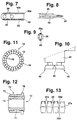
- FIGS. 7 to 10 the furrow tool 35 is closed detect.
- Figure 5 shows the side view with his Mounting holes 38, with the help of which it is screwed 39, 40 is clamped in the device 30 according to FIG. 5.
- the furrow tool 35 carries one at the top and one at the bottom double-sided diameter 43, 43a, each in front a furrow tip 42, 42a runs out.
- the top view after FIG. 8 shows the tip 42 of the furrow tool 35
- FIG. 9 is the front view of the grooving tool 35 10, the lower part of FIG. 9 represents significantly enlarged. There you can see that one on each side of the diameter 43 Furrkante 45, 46 is located.
- Number of lamellae of the lamella strand 27 according to FIG. 1 reached is from the profile belt by the device 30th separated and at a next station the Lamellar strand 27 a lamellar ring 10 in a known manner formed as shown in Figure 11. It consists of a plurality of annularly arranged slats 12 which in Seen longitudinal section, have an L-shaped profile. The Slats are then with their dovetail grooves 22 for anchoring in an insulating molding compound 11 embedded, which if necessary at its hub bore 13 another Can accommodate metal hub. After embedding the Lamella ring, the connecting webs 28 between the Slats turned in the area of the collector tread, see above that the slats are now isolated from each other in the Collector hub are anchored.
- Figure 13 shows a second embodiment of the Invention, namely a lamella strand 27a with double dovetail grooves 22 and 22a. Also there first after embossing the longitudinal grooves 20a and 20b Dovetail groove 22 - as previously described - in the Slotted sides furrowed. This happens in a first Device 30 station. In a subsequent station The same device then becomes the top Dovetail grooves 22a with a knife similar to that in FIG Figures 7 to 10 shown and described - in the Slotted sides furrowed. Depending on the design of the Diameter profiles are different here Embodiments possible.
Landscapes
- Engineering & Computer Science (AREA)
- Manufacturing & Machinery (AREA)
- Power Engineering (AREA)
- Motor Or Generator Current Collectors (AREA)
- Manufacture Of Motors, Generators (AREA)
- Manufacturing Of Electrical Connectors (AREA)
- Manufacture Of Switches (AREA)
- Connection Of Batteries Or Terminals (AREA)
Description
Claims (8)
- Verfahren zum Herstellen eines Kommutators einer Elektromaschine mit einem Kommutatorring (10), der aus über seinen Umfang nebeneinander angeordneten und aus einem Bandmaterial (27) durch eingeprägte Nuten (20a, 20b) geformten Lamellen (12) besteht, die mittels an ihren Innenseiten ausgebildete und in Axialrichtung der Lamellen verlaufende, als Befestigungsmittel dienende Schwalbenschwanznuten (22) in einem Isolierkörper (11) verankert sind, dadurch gekennzeichnet, daß die Schwalbenschwanznuten (22, 22a) durch gleichzeitiges, von beiden Stirnseiten der Lamellen (12) ausgehend und mittels je eines Werkzeuges (35) erfolgendes seitliches Einfurchen der Lamellen gebildet werden derart, daß etwa in der Mitte der Lamellen zwischen den Schwalbenschwanznuten eine nutfreie Zone (26) verbleibt.
- Verfahren nach Anspruch 1, dadurch gekennzeichnet, daß die messerartig ausgebildeten Furchwerkzeuge (35) sich gegenläufig längs der Lamellenseiten hin- und herbewegen.
- Verfahren nach Anspruche 1 oder 2, dadurch gekennzeichnet, daß die Schwalbenschwanznuten mit einem Spezialwerkzeug als Doppel-Schwalbenschwanznuten (22, 22a) an den Lamellenseiten übereinanderliegend eingefurcht werden.
- Verfahren nach einem der Ansprüche 1 bis 3, dadurch gekennzeichnet, daß das Furchen der Lamellen in einer Vorrichtung (30) erfolgt, in welcher der Lamellenstrang (27) so eingelegt ist, daß die langen Schenkel (14) der Lamellen mit ihren Stirnseiten dem Werkzeug (35) zugewandt sind, wobei das Prägen der Nuten (20a) zwischen den Lamellen (12) zuvor in der gleichen Vorrichtung erfolgt.
- Verfahren nach einem der Ansprüche 1 bis 4, dadurch gekennzeichnet, daß der Furchvorgang gleichzeitig in zwei nebeneinanderliegenden Lamellen an den sich gegenüberliegenden Lamellenseiten erfolgt.
- Verfahren nach Anspruch 3, dadurch gekennzeichnet, daß bei den Doppel-Schwalbenschwanznuten (22, 22a) in einer ersten Station der Vorrichtung (30) die unteren Nuten (22) und in einer nachfolgenden Station die oberen Nuten (22a) in die Lamellenseiten eingefurcht werden.
- Kommutator einer Elektromaschine mit einem Kommutatorring (10) aus über den Umfang nebeneinander angeordneten Lamellen (12), die über Befestigungsmittel in einem Isolierstoffkörper (11) befestigt sind, dadurch gekennzeichnet, daß die nach einem Furchverfahren gemäß Anspruch 1 hergestellten Befestigungsmittel als unterbrochene gefurchte Schwalbenschwanznuten (22) ausgebildet sind.
- Kommutator nach Anspruch 7, dadurch gekennzeichnet, daß das Befestigungsmittel als gefurchte Doppel-Schwalbenschwanznut (22a) ausgebildet ist.
Applications Claiming Priority (3)
| Application Number | Priority Date | Filing Date | Title |
|---|---|---|---|
| DE19743086A DE19743086A1 (de) | 1997-09-30 | 1997-09-30 | Verfahren zum Herstellen eines Kommutatorringes für einen Kommutator sowie danach hergestellter Kommutator |
| DE19743086 | 1997-09-30 | ||
| PCT/DE1998/000941 WO1999017409A1 (de) | 1997-09-30 | 1998-04-03 | Verfahren zum herstellen eines kommutatorringes für einen kommutator sowie danach hergestellter kommutator |
Publications (2)
| Publication Number | Publication Date |
|---|---|
| EP1019990A1 EP1019990A1 (de) | 2000-07-19 |
| EP1019990B1 true EP1019990B1 (de) | 2002-07-31 |
Family
ID=7844070
Family Applications (1)
| Application Number | Title | Priority Date | Filing Date |
|---|---|---|---|
| EP98928121A Expired - Lifetime EP1019990B1 (de) | 1997-09-30 | 1998-04-03 | Verfahren zum herstellen eines kommutatorringes für einen kommutator sowie danach hergestellter kommutator |
Country Status (8)
| Country | Link |
|---|---|
| US (1) | US6643912B1 (de) |
| EP (1) | EP1019990B1 (de) |
| JP (1) | JP4138239B2 (de) |
| KR (1) | KR100558593B1 (de) |
| BR (1) | BR9812691A (de) |
| DE (2) | DE19743086A1 (de) |
| ES (1) | ES2181231T3 (de) |
| WO (1) | WO1999017409A1 (de) |
Families Citing this family (3)
| Publication number | Priority date | Publication date | Assignee | Title |
|---|---|---|---|---|
| DE102007051583A1 (de) | 2007-10-29 | 2009-04-30 | Robert Bosch Gmbh | Verfahren zum Herstellen eines Kommutatorrings für einen Rollkommutator einer Elektromaschine, sowie Elektromaschine |
| KR102413954B1 (ko) * | 2015-12-29 | 2022-06-28 | 엘지이노텍 주식회사 | 슬립 링, 모터 및 이를 구비하는 차량 |
| CN108787773B (zh) * | 2018-07-14 | 2024-04-12 | 浙江长城换向器股份有限公司 | 一种换向片挤压工艺及其换向片生产设备 |
Family Cites Families (6)
| Publication number | Priority date | Publication date | Assignee | Title |
|---|---|---|---|---|
| DE1218053B (de) * | 1960-04-30 | 1966-06-02 | Bosch Gmbh Robert | Verfahren zur Herstellung von Lamellen fuer Rollkommutatoren fuer elektrische Maschinen |
| GB2049496B (en) * | 1979-05-18 | 1982-10-27 | Franklin & Freeman London Ltd | Manufacturing commutators for electric rotating machines |
| DE3023108C2 (de) * | 1979-07-02 | 1986-04-24 | Aupac K.K., Tokio/Tokyo | Verfahren zum Herstellen eines Kommutators |
| JP2904623B2 (ja) * | 1990-11-30 | 1999-06-14 | アスモ株式会社 | 小型電動機用整流子及びその製造方法 |
| JPH0787713A (ja) * | 1993-09-17 | 1995-03-31 | Asmo Co Ltd | 電動機用整流子及びその製造方法 |
| DE19543998B4 (de) * | 1995-11-25 | 2007-07-05 | Robert Bosch Gmbh | Verfahren zum Herstellen eines Kommutatorringes für einen Kommutator |
-
1997
- 1997-09-30 DE DE19743086A patent/DE19743086A1/de not_active Withdrawn
-
1998
- 1998-04-03 US US09/509,396 patent/US6643912B1/en not_active Expired - Lifetime
- 1998-04-03 WO PCT/DE1998/000941 patent/WO1999017409A1/de not_active Ceased
- 1998-04-03 KR KR1020007003259A patent/KR100558593B1/ko not_active Expired - Fee Related
- 1998-04-03 DE DE59805033T patent/DE59805033D1/de not_active Expired - Lifetime
- 1998-04-03 EP EP98928121A patent/EP1019990B1/de not_active Expired - Lifetime
- 1998-04-03 BR BR9812691-1A patent/BR9812691A/pt not_active Application Discontinuation
- 1998-04-03 ES ES98928121T patent/ES2181231T3/es not_active Expired - Lifetime
- 1998-04-03 JP JP2000514363A patent/JP4138239B2/ja not_active Expired - Fee Related
Also Published As
| Publication number | Publication date |
|---|---|
| KR100558593B1 (ko) | 2006-03-13 |
| JP4138239B2 (ja) | 2008-08-27 |
| DE19743086A1 (de) | 1999-04-01 |
| BR9812691A (pt) | 2000-08-22 |
| WO1999017409A1 (de) | 1999-04-08 |
| US6643912B1 (en) | 2003-11-11 |
| DE59805033D1 (de) | 2002-09-05 |
| EP1019990A1 (de) | 2000-07-19 |
| ES2181231T3 (es) | 2003-02-16 |
| JP2001518689A (ja) | 2001-10-16 |
| KR20010030734A (ko) | 2001-04-16 |
Similar Documents
| Publication | Publication Date | Title |
|---|---|---|
| DE4138829C2 (de) | Kommutator für einen Motor und Verfahren zu dessen Herstellung | |
| EP3659244A1 (de) | Verfahren und vorrichtung zum wickeln einer wellenwickelmatte sowie damit herstellbare wellenwickelmatte | |
| DE3527640C2 (de) | Vorrichtung und Verfahren zur Herstellung von Riemen aus plastifizierbarem Werkstoff | |
| DE2704158C2 (de) | Preßwalze | |
| DE2704157A1 (de) | Rillenwalze | |
| DE2837797A1 (de) | Verfahren und vorrichtung zum herstellen eines stators fuer einen elektrischen generator | |
| DE2302877C3 (de) | Verfahren zum Herstellen von Metalleinlagen für profilierte und flexible Bänder mit einer Umhüllung | |
| DE2601845A1 (de) | Kollektor und verfahren zu seiner herstellung | |
| EP0791236B1 (de) | Steckkommutator und verfahren zu dessen herstellung | |
| DE19543998B4 (de) | Verfahren zum Herstellen eines Kommutatorringes für einen Kommutator | |
| DE102004003655A1 (de) | Käfig für ein Zylinderrollenlager | |
| DE19743086A1 (de) | Verfahren zum Herstellen eines Kommutatorringes für einen Kommutator sowie danach hergestellter Kommutator | |
| DE4306895C1 (de) | Verfahren zur Herstellung einer Schraubenfeder | |
| DE1261947B (de) | Verfahren zur Herstellung eines Kommutators | |
| DE69205620T2 (de) | Stanzvorrichtung und Verfahren. | |
| DE3516764C2 (de) | ||
| EP0036444A2 (de) | Verfahren zur Herstellung von Formpresskommutatoren | |
| DE3344780C2 (de) | ||
| DE2511301C2 (de) | Vorrichtung zum gleichzeitigen Strangpressen mehrerer Verbundprofile | |
| DE1943104A1 (de) | Schneid- und Stanzmaschine | |
| EP0573439B1 (de) | Rollkommutator für elektrische maschine. | |
| DE3435065C2 (de) | ||
| DE4137400C2 (de) | Preßkommutator und Verfahren zu seiner Herstellung | |
| DE1552099B2 (de) | Vorrichtung zur Herstellung von Lagerkäfigen aus Blech | |
| DE2328698C3 (de) | Verfahren zum Herstellen von Preßstoffkollektoren und dafür geeigneter Kollektorrohling |
Legal Events
| Date | Code | Title | Description |
|---|---|---|---|
| PUAI | Public reference made under article 153(3) epc to a published international application that has entered the european phase |
Free format text: ORIGINAL CODE: 0009012 |
|
| 17P | Request for examination filed |
Effective date: 20000502 |
|
| AK | Designated contracting states |
Kind code of ref document: A1 Designated state(s): DE ES FR IT |
|
| GRAG | Despatch of communication of intention to grant |
Free format text: ORIGINAL CODE: EPIDOS AGRA |
|
| 17Q | First examination report despatched |
Effective date: 20011206 |
|
| GRAG | Despatch of communication of intention to grant |
Free format text: ORIGINAL CODE: EPIDOS AGRA |
|
| GRAH | Despatch of communication of intention to grant a patent |
Free format text: ORIGINAL CODE: EPIDOS IGRA |
|
| GRAH | Despatch of communication of intention to grant a patent |
Free format text: ORIGINAL CODE: EPIDOS IGRA |
|
| GRAA | (expected) grant |
Free format text: ORIGINAL CODE: 0009210 |
|
| AK | Designated contracting states |
Kind code of ref document: B1 Designated state(s): DE ES FR IT |
|
| REF | Corresponds to: |
Ref document number: 59805033 Country of ref document: DE Date of ref document: 20020905 |
|
| ET | Fr: translation filed | ||
| REG | Reference to a national code |
Ref country code: ES Ref legal event code: FG2A Ref document number: 2181231 Country of ref document: ES Kind code of ref document: T3 |
|
| PLBE | No opposition filed within time limit |
Free format text: ORIGINAL CODE: 0009261 |
|
| STAA | Information on the status of an ep patent application or granted ep patent |
Free format text: STATUS: NO OPPOSITION FILED WITHIN TIME LIMIT |
|
| 26N | No opposition filed |
Effective date: 20030506 |
|
| PGFP | Annual fee paid to national office [announced via postgrant information from national office to epo] |
Ref country code: ES Payment date: 20120423 Year of fee payment: 15 |
|
| PGFP | Annual fee paid to national office [announced via postgrant information from national office to epo] |
Ref country code: IT Payment date: 20130424 Year of fee payment: 16 |
|
| PG25 | Lapsed in a contracting state [announced via postgrant information from national office to epo] |
Ref country code: IT Free format text: LAPSE BECAUSE OF NON-PAYMENT OF DUE FEES Effective date: 20140403 |
|
| REG | Reference to a national code |
Ref country code: ES Ref legal event code: FD2A Effective date: 20150527 |
|
| PG25 | Lapsed in a contracting state [announced via postgrant information from national office to epo] |
Ref country code: ES Free format text: LAPSE BECAUSE OF NON-PAYMENT OF DUE FEES Effective date: 20140404 |
|
| REG | Reference to a national code |
Ref country code: FR Ref legal event code: PLFP Year of fee payment: 19 |
|
| REG | Reference to a national code |
Ref country code: FR Ref legal event code: PLFP Year of fee payment: 20 |
|
| PGFP | Annual fee paid to national office [announced via postgrant information from national office to epo] |
Ref country code: FR Payment date: 20170424 Year of fee payment: 20 |
|
| PGFP | Annual fee paid to national office [announced via postgrant information from national office to epo] |
Ref country code: DE Payment date: 20170623 Year of fee payment: 20 |
|
| REG | Reference to a national code |
Ref country code: DE Ref legal event code: R081 Ref document number: 59805033 Country of ref document: DE Owner name: SEG AUTOMOTIVE GERMANY GMBH, DE Free format text: FORMER OWNER: ROBERT BOSCH GMBH, 70469 STUTTGART, DE |
|
| REG | Reference to a national code |
Ref country code: DE Ref legal event code: R071 Ref document number: 59805033 Country of ref document: DE |
|
| REG | Reference to a national code |
Ref country code: FR Ref legal event code: TP Owner name: SEG AUTOMOTIVE GERMANY GMBH, DE Effective date: 20180315 |