EP1017557B1 - Form für würfeleckenbahnen und verfahren zu deren herstellung - Google Patents
Form für würfeleckenbahnen und verfahren zu deren herstellung Download PDFInfo
- Publication number
- EP1017557B1 EP1017557B1 EP98930255A EP98930255A EP1017557B1 EP 1017557 B1 EP1017557 B1 EP 1017557B1 EP 98930255 A EP98930255 A EP 98930255A EP 98930255 A EP98930255 A EP 98930255A EP 1017557 B1 EP1017557 B1 EP 1017557B1
- Authority
- EP
- European Patent Office
- Prior art keywords
- groove
- lamina
- cube corner
- laminae
- forming
- Prior art date
- Legal status (The legal status is an assumption and is not a legal conclusion. Google has not performed a legal analysis and makes no representation as to the accuracy of the status listed.)
- Expired - Lifetime
Links
- 238000004519 manufacturing process Methods 0.000 title claims abstract description 23
- 238000000034 method Methods 0.000 claims abstract description 50
- 239000000758 substrate Substances 0.000 claims description 4
- 230000003362 replicative effect Effects 0.000 claims description 2
- 230000003287 optical effect Effects 0.000 abstract description 24
- 238000003754 machining Methods 0.000 description 42
- 239000000463 material Substances 0.000 description 21
- PXHVJJICTQNCMI-UHFFFAOYSA-N Nickel Chemical compound [Ni] PXHVJJICTQNCMI-UHFFFAOYSA-N 0.000 description 20
- 238000005520 cutting process Methods 0.000 description 11
- 230000015572 biosynthetic process Effects 0.000 description 10
- 229910052759 nickel Inorganic materials 0.000 description 10
- 230000001154 acute effect Effects 0.000 description 8
- 229910003460 diamond Inorganic materials 0.000 description 7
- 239000010432 diamond Substances 0.000 description 7
- 239000004005 microsphere Substances 0.000 description 6
- 239000013598 vector Substances 0.000 description 5
- 230000001186 cumulative effect Effects 0.000 description 4
- 239000004417 polycarbonate Substances 0.000 description 4
- 229920000515 polycarbonate Polymers 0.000 description 4
- 239000000853 adhesive Substances 0.000 description 3
- 230000001070 adhesive effect Effects 0.000 description 3
- 238000009713 electroplating Methods 0.000 description 3
- 229920003229 poly(methyl methacrylate) Polymers 0.000 description 3
- -1 polyethylene Polymers 0.000 description 3
- 230000004044 response Effects 0.000 description 3
- 238000007789 sealing Methods 0.000 description 3
- 229910001369 Brass Inorganic materials 0.000 description 2
- 239000004698 Polyethylene Substances 0.000 description 2
- 150000001252 acrylic acid derivatives Chemical class 0.000 description 2
- 229910052782 aluminium Inorganic materials 0.000 description 2
- XAGFODPZIPBFFR-UHFFFAOYSA-N aluminium Chemical compound [Al] XAGFODPZIPBFFR-UHFFFAOYSA-N 0.000 description 2
- 238000003491 array Methods 0.000 description 2
- 230000008901 benefit Effects 0.000 description 2
- 239000010951 brass Substances 0.000 description 2
- 238000005266 casting Methods 0.000 description 2
- 238000005229 chemical vapour deposition Methods 0.000 description 2
- 238000004049 embossing Methods 0.000 description 2
- 230000001788 irregular Effects 0.000 description 2
- 229910052751 metal Inorganic materials 0.000 description 2
- 239000002184 metal Substances 0.000 description 2
- 238000003801 milling Methods 0.000 description 2
- 229920000728 polyester Polymers 0.000 description 2
- 229920000573 polyethylene Polymers 0.000 description 2
- 239000004926 polymethyl methacrylate Substances 0.000 description 2
- 230000008569 process Effects 0.000 description 2
- RYGMFSIKBFXOCR-UHFFFAOYSA-N Copper Chemical compound [Cu] RYGMFSIKBFXOCR-UHFFFAOYSA-N 0.000 description 1
- 239000004593 Epoxy Substances 0.000 description 1
- 229920002430 Fibre-reinforced plastic Polymers 0.000 description 1
- 229910001335 Galvanized steel Inorganic materials 0.000 description 1
- 229920005372 Plexiglas® Polymers 0.000 description 1
- 229920003182 Surlyn® Polymers 0.000 description 1
- 239000006096 absorbing agent Substances 0.000 description 1
- 229920006397 acrylic thermoplastic Polymers 0.000 description 1
- 239000000654 additive Substances 0.000 description 1
- 238000013459 approach Methods 0.000 description 1
- 239000011230 binding agent Substances 0.000 description 1
- 229920006217 cellulose acetate butyrate Polymers 0.000 description 1
- 238000003486 chemical etching Methods 0.000 description 1
- 239000003086 colorant Substances 0.000 description 1
- 239000002131 composite material Substances 0.000 description 1
- 239000000356 contaminant Substances 0.000 description 1
- 229910052802 copper Inorganic materials 0.000 description 1
- 239000010949 copper Substances 0.000 description 1
- 238000000151 deposition Methods 0.000 description 1
- 230000008021 deposition Effects 0.000 description 1
- 230000009977 dual effect Effects 0.000 description 1
- 239000000975 dye Substances 0.000 description 1
- 238000005323 electroforming Methods 0.000 description 1
- 238000005516 engineering process Methods 0.000 description 1
- 239000011151 fibre-reinforced plastic Substances 0.000 description 1
- 239000012530 fluid Substances 0.000 description 1
- 239000008397 galvanized steel Substances 0.000 description 1
- 229920000554 ionomer Polymers 0.000 description 1
- 238000010030 laminating Methods 0.000 description 1
- 238000000608 laser ablation Methods 0.000 description 1
- 238000005259 measurement Methods 0.000 description 1
- 230000007246 mechanism Effects 0.000 description 1
- 150000002739 metals Chemical class 0.000 description 1
- 238000000465 moulding Methods 0.000 description 1
- 239000002245 particle Substances 0.000 description 1
- 238000005240 physical vapour deposition Methods 0.000 description 1
- 239000000049 pigment Substances 0.000 description 1
- 229920003023 plastic Polymers 0.000 description 1
- 239000004033 plastic Substances 0.000 description 1
- 229920006289 polycarbonate film Polymers 0.000 description 1
- 229920002635 polyurethane Polymers 0.000 description 1
- 239000004814 polyurethane Substances 0.000 description 1
- 229920000915 polyvinyl chloride Polymers 0.000 description 1
- 229920002620 polyvinyl fluoride Polymers 0.000 description 1
- 238000003825 pressing Methods 0.000 description 1
- 230000005855 radiation Effects 0.000 description 1
- 230000009467 reduction Effects 0.000 description 1
- 230000010076 replication Effects 0.000 description 1
- 239000011347 resin Substances 0.000 description 1
- 229920005989 resin Polymers 0.000 description 1
- 230000035945 sensitivity Effects 0.000 description 1
- 239000002689 soil Substances 0.000 description 1
- 238000003860 storage Methods 0.000 description 1
- 239000000126 substance Substances 0.000 description 1
- 230000003746 surface roughness Effects 0.000 description 1
- ISXSCDLOGDJUNJ-UHFFFAOYSA-N tert-butyl prop-2-enoate Chemical compound CC(C)(C)OC(=O)C=C ISXSCDLOGDJUNJ-UHFFFAOYSA-N 0.000 description 1
- 229920001187 thermosetting polymer Polymers 0.000 description 1
- 238000003466 welding Methods 0.000 description 1
Images


Classifications
-
- B—PERFORMING OPERATIONS; TRANSPORTING
- B29—WORKING OF PLASTICS; WORKING OF SUBSTANCES IN A PLASTIC STATE IN GENERAL
- B29D—PRODUCING PARTICULAR ARTICLES FROM PLASTICS OR FROM SUBSTANCES IN A PLASTIC STATE
- B29D11/00—Producing optical elements, e.g. lenses or prisms
- B29D11/00605—Production of reflex reflectors
- B29D11/00625—Moulds for reflex reflectors
-
- B—PERFORMING OPERATIONS; TRANSPORTING
- B29—WORKING OF PLASTICS; WORKING OF SUBSTANCES IN A PLASTIC STATE IN GENERAL
- B29D—PRODUCING PARTICULAR ARTICLES FROM PLASTICS OR FROM SUBSTANCES IN A PLASTIC STATE
- B29D11/00—Producing optical elements, e.g. lenses or prisms
-
- Y—GENERAL TAGGING OF NEW TECHNOLOGICAL DEVELOPMENTS; GENERAL TAGGING OF CROSS-SECTIONAL TECHNOLOGIES SPANNING OVER SEVERAL SECTIONS OF THE IPC; TECHNICAL SUBJECTS COVERED BY FORMER USPC CROSS-REFERENCE ART COLLECTIONS [XRACs] AND DIGESTS
- Y10—TECHNICAL SUBJECTS COVERED BY FORMER USPC
- Y10S—TECHNICAL SUBJECTS COVERED BY FORMER USPC CROSS-REFERENCE ART COLLECTIONS [XRACs] AND DIGESTS
- Y10S425/00—Plastic article or earthenware shaping or treating: apparatus
- Y10S425/03—Laminated mold
Definitions
- the present invention relates generally to molds suitable for use in forming cube corner retroreflective sheeting and to methods for making the same.
- the present invention relates to molds formed from a plurality of thin laminae and to methods for making the same.
- Retroreflective materials are characterized by the ability to redirect light incident on the material back toward the originating light source. This property has led to the wide-spread use of retroreflective sheeting in a variety of conspicuity applications. Retroreflective sheeting is frequently used on flat, rigid articles such as, for example, road signs and barricades; however, it is also used on irregular or flexible surfaces. For example, retroreflective sheeting can be adhered to the side of a truck trailer, which requires the sheeting to pass over corrugations and protruding rivets, or the sheeting can be adhered to a flexible body portion such as a road worker's safety vest or other such safety garment.
- the retroreflective sheeting desirably possesses the ability to conform to the underlying surface without sacrificing retroreflective performance. Additionally, retroreflective sheeting is frequently packaged and shipped in roll form, thus requiring the sheeting to be sufficiently flexible to be rolled around a core.
- Microsphere-based sheeting Two known types of retroreflective sheeting are microsphere-based sheeting and cube corner sheeting.
- Microsphere-based sheeting employs a multitude of microspheres typically at least partially embedded in a binder layer and having associated specular or diffuse reflecting materials (e.g., pigment particles, metal flakes or vapor coats, etc.) to retroreflect incident light.
- specular or diffuse reflecting materials e.g., pigment particles, metal flakes or vapor coats, etc.
- microsphere-based sheeting can generally be adhered to corrugated or flexible surfaces.
- microsphere based sheeting exhibits a relatively orientationally uniform total light return when rotated about an axis normal to the surface of the sheeting.
- microsphere-based sheeting has a relatively low sensitivity to the orientation at which the sheeting is placed on a surface.
- such sheeting has a lower retroreflective efficiency than cube corner sheeting.
- Cube corner retroreflective sheeting comprises a body portion typically having a substantially planar base surface and a structured surface comprising a plurality of cube corner elements opposite the base surface.
- Each cube-corner element comprises three mutually substantially perpendicular optical faces that intersect at a single reference point, or apex.
- the base of the cube corner element acts as an aperture through which light is transmitted into the cube corner element.
- light incident on the base surface of the sheeting is refracted at the base surface of the sheeting, transmitted through the bases of the cube corner elements disposed on the sheeting, reflected from each of the three perpendicular cube-corner optical faces, and redirected toward the light source.
- the symmetry axis, also called the optical axis, of a cube corner element is the axis that extends through the cube corner apex and forms an equal angle with the three optical faces of the cube corner element.
- Cube corner elements typically exhibit the highest optical efficiency in response to light incident on the base of the element roughly along the optical axis. The amount of light retroreflected by a cube corner retroreflector drops as the incidence angle deviates from the optical axis.
- the maximum retroreflective efficiency of cube corner retroreflective sheeting is a function of the geometry of the cube corner elements on the structured surface of the sheeting.
- the terms 'active area' and 'effective aperture' are used in the cube corner arts to characterize the portion of a cube corner element that retroreflects light incident on the base of the element.
- a detailed teaching regarding the determination of the active aperture for a cube corner element design is beyond the scope of the present disclosure.
- One procedure for determining the effective aperture of a cube corner geometry is presented in Eckhardt, Applied Optics, v. 10, n. 7, July, 1971, pp. 1559-1566.
- U.S. Pat. No. 835,648 to Straubel also discusses the concept of effective aperture.
- the active area can be determined by the topological intersection of the projection of the three cube corner faces onto a plane normal to the refracted incident light with the projection of the image surfaces for the third reflections onto the same plane.
- the term 'percent active area' is then defined as the active area divided by the total area of the projection of the cube corner faces.
- the retroreflective efficiency of retroreflective sheeting correlates directly to the percentage active area of the cube corner elements on the sheeting.
- the optical characteristics of the retroreflection pattern of retroreflective sheeting are, in part, a function of the geometry of the cube corner elements.
- distortions in the geometry of the cube corner elements can cause corresponding distortions in the optical characteristics of the sheeting.
- cube corner elements of retroreflective sheeting are typically made from a material having a relatively high elastic modulus sufficient to inhibit the physical distortion of the cube corner elements during flexing or elastomeric stretching of the sheeting.
- Cube corner retroreflective sheeting is manufactured by first manufacturing a master mold that includes an image, either negative or positive, of a desired cube corner element geometry.
- the mold can be replicated using nickel electroplating, chemical vapor deposition or physical vapor deposition to produce tooling for forming cube corner retroreflective sheeting.
- U.S. Pat. No. 5,156,863 to Pricone, et al. provides an illustrative overview of a process for forming tooling used in the manufacture of cube corner retroreflective sheeting.
- Known methods for manufacturing the master mold include pin-bundling techniques, direct machining techniques, and laminate techniques. Each of these techniques has benefits and limitations.
- pin bundling techniques a plurality of pins, each having a geometric shape on one end, are assembled together to form a cube-corner retroreflective surface.
- U.S. Pat. Nos. 1,591,572 (Stimson), 3,926,402 (Heenan), 3,541,606 (Heenan et al.) and 3,632,695 (Howell) provide illustrative examples.
- Pin bundling techniques offer the ability to manufacture a wide variety of cube corner geometries in a single mold. However, pin bundling techniques are economically and technically impractical for making small cube corner elements (e.g. less than about 1.0 millimeters).
- German Provisional Publication (OS) 19 17 292 International Publication Nos. WO 94/18581 (Bohn, et al.), WO 97/04939 (Mimura et al.), and WO 97/04940 (Mimura et al.), disclose a molded reflector wherein a grooved surface is formed on a plurality of plates. The plates are then tilted by a certain angle and each second plate is shifted crosswise.
- German Patent DE 42 36 799 to Gubela discloses a method for producing a molding tool with a cubical surface for the production of cube corners. An oblique surface is ground or cut in a first direction over the entire length of one edge of a band. A plurality of notches are then formed in a second direction to form cube corner reflectors on the band. Finally, a plurality of notches are formed vertically in the sides of the band.
- German Provisional Patent 44 10 994 C2 to Gubela is a related patent. The reflectors disclosed in Patent 44 10 994 C2 are characterized by the reflecting surfaces having concave curvature.
- the present invention relates to providing a master mold suitable for use in forming retroreflective sheeting from a plurality of laminae and methods of making the same.
- master molds manufactured according to methods disclosed herein enable the manufacture of retroreflective cube corner sheeting that exhibits retroreflective efficiency levels approaching 100%.
- the disclosed methods enable the manufacture of cube corner retroreflective elements having a width of 0.010 millimeters or less.
- the present application enables the manufacture of a cube corner retroreflective sheeting that exhibits symmetrical retroreflective performance in at least two different orientations.
- Efficient, cost-effective methods of making molds formed from a plurality of laminae are also disclosed.
- a reduction of the number of laminae necessary to produce a given density of cube corner elements in a sheeting is disclosed, thereby reducing the time and expense associated with manufacturing such molds.
- a lamina suitable for use in a mold for use in forming retroreflective cube corner articles is provided according to claim 1.
- each cube corner element is preferably formed on a single lamina. All three optical faces are preferably formed by the machining process to ensure optical quality surfaces.
- a planar interface is preferably maintained between adjacent first and second major surfaces during the machining phase and subsequent thereto so as to minimize alignment problems and damage due to handling of the laminae.
- Retroreflective Cube Corner Sheeting Mold and Sheeting Formed Therefrom U.S. Serial No. 08/886998
- Retroreflective Cube Corner Sheeting, Molds Therefore, and Methods of Making the Same U.S. Serial No. 08/887390
- Tiled Retroreflective Sheeting Composed of Highly Canted Cube Corner Elements U.S. Serial No. 08/887389
- Retroreflective Cube Corner Sheeting Mold and Method of Making the Same U.S. Serial No. 08/887074
- Dual Orientation Retroreflective Sheeting U.S. Serial No. 08/887006
- the disclosed embodiments can utilize full cube corner elements of a variety of sizes and shapes.
- the base edges of adjacent full cube corner elements in an array are not all in the same plane.
- the base edges of adjacent truncated cube corner elements in an array are typically coplanar.
- Full cube corner elements have a higher total light return than truncated cube corner elements for a given amount of cant, but the full cubes lose total light return more rapidly at higher entrance angles.
- One benefit of full cube corner elements is higher total light return at low entrance angles, without too large of a loss in performance at higher entrance angles.
- Predicted total light return (TLR) for a cube corner matched pair array can be calculated from a knowledge of percent active area and ray intensity. Ray intensity may be reduced by front surface losses and by reflection from each of the three cube corner surfaces for a retroreflected ray. Total light return is defined as the product of percent active area and ray intensity, or a percentage of the total incident light which is retroreflected.
- TLR total light return
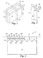
- Figs. 1-2 depict a representative lamina 10 useful in the manufacture of a mold suitable for forming retroreflective sheeting.
- Lamina 10 includes a first major surface 12 and an opposing second major surface 14.
- Lamina 10 further includes a working surface 16 and an opposing bottom surface 18 extending between first major surface 12 and second major surface 14.
- Lamina 10 further includes a first end surface 20 and an opposing second end surface 22.
- lamina 10 is a right rectangular polyhedron wherein opposing surfaces are substantially parallel. However, it will be appreciated that opposing surfaces of lamina 10 need not be parallel.
- lamina 10 can be characterized in three dimensional space by superimposing a Cartesian coordinate system onto its structure.
- a first reference plane 24 is centered between major surfaces 12 and 14.
- First reference plane 24, referred to as the x-z plane has the y-axis as its normal vector.
- a second reference plane 26, referred to as the x-y plane extends substantially coplanar with working surface 16 of lamina 10 and has the z-axis as its normal vector.
- a third reference plane 28, referred to as the y-z plane is centered between first end surface 20 and second end surface 22 and has the x-axis as its normal vector.
- Cartesian reference planes as set forth herein. However, it will be appreciated that such geometric attributes can be described using other coordinate systems or with reference to the structure of the lamina.
- Figs. 2-12 illustrate the formation of a structured surface comprising a plurality of optically opposing cube corner elements in the working surface 16 of lamina 10.
- a first groove set comprising at least two parallel, adjacent grooves 30a, 30b, 30c, etc. (collectively referred to as 30) is formed in the working surface 16 of lamina 10 (Figs. 2-4).
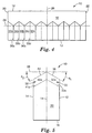
- a second groove set comprising at least two parallel, adjacent grooves 38a, 38b, 38c, etc. (collectively referred to as 38) is also formed in the working surface 16 of lamina 10 (Figs. 5-7).
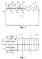
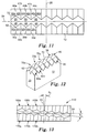
- the first and second groove sets intersect approximately along a first reference plane 24 to form a structured surface including a plurality of alternating peaks and v-shaped valleys (Fig. 8). It is not necessary for the groove sets 30, 38 to be aligned, as illustrated in Fig. 8. Alternatively, the peaks and v-shaped valleys can be off-set with respect to each other, such as illustrated in Fig. 13.
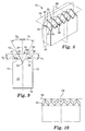
- a third groove 46 is then formed in the working surface 16 of lamina 10 (Figs. 9-11).
- third groove 46 extends along an axis approximately perpendicular to the direction in which the first and second groove sets were formed. Formation of third groove 46 results in a structured surface that includes a plurality of cube corner elements having three mutually perpendicular optical faces on the lamina (Fig. 12).
- the term 'groove set' refers to all parallel grooves formed in working surface 16 of the lamina 10.
- a first groove set comprising at least two parallel, adjacent grooves 30a, 30b, 30c, etc. (collectively referred to by the reference numeral 30) is formed in the working surface 16 of lamina 10.
- the grooves define first groove surfaces 32a, 32b, 32c, etc. (collectively referred to as 32) and second groove surfaces 34b, 34c, 34d, etc. (collectively referred to as 34) that intersect at groove vertices 33b, 33c, 33d, etc. (collectively referred to as 33).
- the groove forming operation may form a single groove surface 32a.
- Groove surfaces 32a and 34b of adjacent grooves intersect approximately orthogonally along a reference edge 36a.
- the terms 'substantially orthogonally' or 'approximately orthogonally' shall mean that the dihedral angle between the respective surfaces measures approximately 90°; slight variations in orthogonality as disclosed and claimed in U.S. Pat. No. 4,775,219 to Appeldorn are contemplated.
- adjacent groove surfaces 32b and 34c intersect approximately orthogonally along first reference edge 36b. Preferably this pattern is repeated across the entire working surface 16 of lamina 10 as illustrated in Figs. 3-4.
- the respective groove vertices 33 are preferably separated by a distance that measures between about 0.01 millimeters and about 1.0 millimeters.
- the grooves 30 are formed such that the respective groove vertices 33 and the respective first reference edges 36 extend along an axis that intersects the first major surface 12 and the working surface 16 of lamina 10.
- the working surface 16 of the lamina 10 includes a portion which remains unaltered by the formation of the plurality of grooves 30.
- the grooves can also be formed such that the respective groove vertices 33 and first reference edges 36 extend along an axis that intersects the first major surface 12 and the second major surface 14 of lamina 10 by forming the grooves deeper into the working surface 16.
- the grooves 30 are formed such that each of the first reference edges 36 are disposed in planes that intersect the first reference plane 24 and the second reference plane 26 at orthogonal angles such that, in the top view of Fig. 4, the reference edges 36 appear perpendicular to reference plane 24.
- the grooves 30 are formed such that the first reference edges 36 are all disposed in a common plane that intersects the second reference plane 26 at an acute angle ⁇ 1 of approximately 27.8°.
- Grooves 30 can alternately be formed such that the reference edges 36 intersect reference plane 26 at angles different than 27.8°.
- a second groove set comprising at least two parallel, adjacent grooves 38a, 38b, 38c, etc. (collectively referred to as 38) is formed in the working surface 16 of lamina 10.
- Grooves 38 define third groove surfaces 40a, 40b, 40c, etc. (collectively referred to as 40) and fourth groove surfaces 42b, 42c, 42d, etc. (collectively referred to as 42) that intersect at groove vertices 41b, 41c, 41d, etc. (collectively referred to as 41) as shown.
- the groove forming operation may form a single groove surface 40a.
- Groove surfaces 40a and 42b of adjacent grooves intersect approximately orthogonally along a reference edge 44a, which, for the purposes of the present disclosure, means that the dihedral angle between surfaces 40a and 42b is approximately 90°.
- adjacent groove surfaces 40b and 42c intersect approximately orthogonally along a second reference edge 44b.
- this pattern is repeated across the entire working surface 16 of lamina 10.
- Groove vertices 41 are preferably spaced apart by between about 0.01 millimeters and 0.10 millimeters.
- the grooves 38 are formed such that the reference edges 44 extend along an axis that intersects the second major surface 14 and the working surface 16 of lamina 10.
- the reference edges 44 (and groove vertices 41) intersect the second reference plane 26 of lamina 10 at an acute angle ⁇ 2 that measures approximately 27.8°.
- ⁇ 2 that measures approximately 27.8°.
- grooves 38 are formed such that the respective reference edges 44 are disposed in planes that intersect the first reference plane 24 and second reference plane 26 at orthogonal angles such that, in the top view of Fig. 7, reference edges 44 appear perpendicular to first reference plane 24.
- grooves 38 are preferably formed such that the groove vertices 41 are substantially coplanar with groove vertices 33, and the reference edges 44 are substantially coplanar with reference edges 36.
- groove vertices 33, 41 and reference edges 36, 44 can be shifted with respect to each other.
- the depth of the groove vertices 33, 41 can vary with respect to one another.
- Fig. 8 presents a perspective view of a representative lamina 10 upon completion of forming the grooves 38.
- Lamina 10 includes a series of grooves 30, 38 formed in the working surface 16 thereof as described above.
- the reference edges 36, 44 intersect approximately along the first reference plane 24 to define a plurality of peaks.
- groove vertices 33, 41 intersect approximately along the first reference plane to define a plurality of valleys between the peaks.
- Figs. 9-12 illustrate an embodiment of lamina 10 following formation of a third groove 46 in lamina 10.
- third groove 46 defines a fifth groove surface 48 and a sixth groove surface 50 that intersect at a groove vertex 52 along an axis that is contained by the first reference plane 24.
- third groove 46 is formed such that fifth groove surface 48 is disposed in a plane that is substantially orthogonal to the first groove surfaces 32 and the second groove surfaces 34. This can be accomplished by forming third groove 46 such that fifth groove surface 48 forms an angle equal to angle ⁇ 1 with first reference plane 24; sixth groove surface likewise preferably forms an angle equal to angle ⁇ 2 with first reference plane 24, where ⁇ 1 and ⁇ 2 are the same ⁇ 1 and ⁇ 2 illustrated in Fig. 5.
- Formation of the fifth groove surface 48 yields a plurality of cube corner elements 60a, 60b, etc. (collectively referred to as 60) in working surface 16 of lamina 10.
- Each cube corner element 60 is defined by a first groove surface 32, a second groove surface 34, and a portion of fifth groove surface 48 that mutually intersect at a point to define a cube corner peak, or apex 62.
- sixth groove surface 50 is disposed in a plane that is substantially orthogonal to the third groove surfaces 40 and the fourth groove surfaces 42 that mutually intersect at a point to define a cube corner peak, or apex 72. Formation of the sixth groove surface 50 also yields a plurality of cube corner elements 70a, 70b, etc.
- Each cube corner element 70 is defined by a third groove surface 40, a fourth groove surface 42 and a portion of sixth groove surface 50.
- both fifth groove surface 48 and sixth groove surface 50 form a plurality of cube corner elements on the working surface 16 of lamina 10.
- third groove 46 can be formed such that only the fifth groove surface 48 or the sixth groove surface 50 forms cube corner elements.
- the dihedral angle defined by opposing surfaces of grooves 30 and 38 measures 90°.
- the first and second reference edges 36, 44 are disposed in planes that intersect the first reference plane 24 at an orthogonal angle and that intersect the second reference plane 26 at an orthogonal angle.
- the reference edges 36 and 44 extend along axes that are substantially perpendicular to first reference plane 24.
- Reference edges 36 extend along axes that intersect the first major surface 12 of lamina 10 and that intersect the second reference plane 26 at an acute angle of approximately 27.8°.
- Reference edges 44 likewise extend along axes that intersect the second major surface 14 of lamina 10 and that intersect the second reference plane 26 at an acute angle of approximately 27.8°.
- the vertex of third groove 46 extends along an axis that is substantially parallel to first reference plane 24 and the dihedral angle between fifth groove surface 48 and sixth groove surface 50 is approximately 55.6°.
- working surface 16 is formed using conventional precision machining tooling and techniques such as, for example, ruling, milling, grooving, and fly-cutting.
- second major surface 14 of lamina 10 can be registered to a substantially planar surface such as the surface of a precision machining tool and each groove 30a, 30b, etc. of the first groove set can be formed in working surface 16 by moving a V-shaped cutting tool having an included angle of 90° along an axis that intersects the first working surface 12 and the second reference plane 26 at an angle ⁇ 1 of 27.8°.
- each groove 30 is formed at the same depth in the working surface and the cutting tool is moved laterally by the same distance between adjacent grooves such that grooves are substantially identical.
- first major surface 12 of lamina 10 can be registered to the planar surface and each groove 38a, 38b, etc. can be formed in working surface 16 by moving a V-shaped cutting tool having an included angle of 90° along an axis that intersects the second working surface 14 and the second reference plane 26 at an angle ⁇ 2 of 27.8°.
- bottom surface 18 of lamina 10 can be registered to the planar surface and third groove 46 may be formed in working surface 16 by moving a V-shaped cutting tool having an included angle of 55.6° along an axis substantially parallel with base surface 18 and contained by first reference plane 24.
- a plurality of laminae 10 having a working surface 16 that includes cube corner elements 60, 70 formed as described above can be assembled together in a suitable fixture.
- Working surface 16 is then replicated using precision replication techniques such as, for example, nickel electroplating to form a negative copy of working surface 16.
- Electroplating techniques are known to one of ordinary skill in the retroreflective arts. See e.g. U.S. Pat. Nos. 4,478.769 and 5,156,863 to Pricone et al.
- the negative copy of working surface 16 can then be used as a mold for forming retroreflective articles having a positive copy of working surface 16.
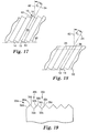
- Figs. 16-24 present another method for forming a plurality of laminae suitable for use in a mold suitable for forming retroreflective articles.
- a plurality of cube corner elements are formed in the working surfaces of a plurality of laminae while the laminae are held together in an assembly, rather than individually, as described above.
- the plurality of laminae 10 are preferably assembled such that their working surfaces 16 are substantially coplanar.
- the laminae 10 are oriented such that their respective first reference planes are disposed at a first angle, ⁇ 1, relative to a fixed reference axis 82 (Fig. 17).
- a first groove set including at least two V-shaped grooves is formed in the working surface 16 of the plurality of laminae 10 (Figs. 18-19). The laminae are then oriented such that their respective first reference planes are disposed at a second angle, ⁇ 2 , relative to the reference axis 82 (Fig. 20).
- a second groove set including at least two V-shaped grooves is formed in the working surface 16 of the plurality of laminae 10 (Figs. 21-22).
- a third groove set that preferably includes at least one V-shaped groove in the working surface 16 of each lamina 10 is also formed (Fig. 23). Formation of the third groove set results in a structured surface that includes a plurality of cube corner elements on the working surface of the plurality of laminae 10 (Fig. 24).
- a plurality of thin laminae 10 are assembled together such that the first major surface 12 of one lamina 10 is adjacent the second major surface 14 of an adjacent lamina 10.
- the laminae 10 are assembled in a conventional fixture capable of securing the plurality of laminae adjacent one another. Details of the fixture are not critical. However, the fixture defines a base plane 80 which is preferably substantially parallel to the bottom surfaces 18 of the laminae 10 when the laminae 10 are positioned as depicted in Fig. 16.
- the plurality of laminae 10 can be characterized by a Cartesian coordinate system as described above.
- the working surfaces 16 of the plurality of laminae 10 are substantially coplanar when the laminae are positioned with their respective first reference planes 24 perpendicular to base plane 80.
- the laminae 10 are oriented to have their respective first reference planes 24 disposed at a first angle ⁇ 1 , from a fixed reference axis 82 normal to base plane 80.
- ⁇ 1 is approximately 27.8°.
- ⁇ 1 can alternately be between about 1° and about 85°, but more preferably is between about 10° and about 60°.
- a first groove set comprising a plurality of parallel adjacent V-shaped grooves 30a, 30b, 30c, etc. (collectively referred to as 30) is formed in the working surfaces 16 of the plurality of laminae 10 with the lamina disposed at angle ⁇ 1 .
- At least two adjacent grooves 30 are formed in working surface 16 of the plurality of laminae 10.
- the grooves 30 define first groove surfaces 32a, 32b, 32c, etc. (collectively referred to as 32) and second groove surfaces 34b, 34c, 34d, etc. (collectively referred to as 34) that intersect at groove vertices 33b, 33c, 33d, etc. (collectively referred to as 33) as shown.
- the groove forming operation may form a single groove surface 32a.
- groove surfaces 32a and 34b of adjacent grooves intersect approximately orthogonally along a reference edge 36a.
- adjacent groove surfaces 32b and 34c intersect approximately orthogonally along reference edge 36b.
- this pattern is repeated across the entire working surfaces 16 of the laminae 10.
- the grooves 30 can be formed by removing portions of working surface 16 of the plurality of laminae using a wide variety of material removal techniques including precision machining techniques such as milling, ruling, grooving and fly-cutting, as well as chemical etching or laser ablation techniques.
- the grooves 30 are formed in a high-precision machining operation in which a diamond cutting tool having a 90° included angle repeatedly moves transversely across the working surfaces 16 of the plurality of laminae 10 along an axis that is substantially parallel to base plane 80.
- the diamond cutting tool can alternately move along an axis that is non-parallel to base plane 80 such that the tool cuts at a varying depth across the plurality of laminae 10.
- the machining tool can be held stationary while the plurality of laminae are placed in motion; any relative motion between the laminae 10 and the machining tool is contemplated.
- the grooves 30 are formed at a depth such that the respective first reference edges 36 intersect the first major surface 12 and the second major surface 14 of each lamina.
- the reference edges 36 and groove vertices 33 form substantially continuous lines that extend along an axis parallel to base plane 80.
- grooves 30 are formed such that the reference edges 36 are disposed in a plane that intersects the respective first reference planes 24 and the second reference plane 26 at orthogonal angles.
- the first reference edges 36 would appear perpendicular to the respective first reference planes 24.
- the grooves 30 can also be formed at lesser depths, as depicted in Figs. 2-4, or along different axes.
- the laminae 10 are next oriented to have their respective first reference planes 24 disposed at a second angle ⁇ 2 , from fixed reference axis 82 normal to base plane 80.
- ⁇ 2 is approximately 27.8°.
- ⁇ 2 can alternately be between about 1° and about 85°, and preferably between about 10° and about 60°.
- the angle ⁇ 2 is independent of angle ⁇ 1 and need not be equal to ⁇ 1 .
- the laminae 10 are preferably removed from the fixture and reassembled with their respective first reference planes disposed at angle ⁇ 2 .
- a second groove set comprising a plurality of parallel adjacent V-shaped grooves 38b, 38c, etc. (collectively referred to as 38) is formed in the working surfaces 16 of the laminae 10 with the laminae disposed at angle ⁇ 2 .
- At least two adjacent grooves 38 are formed in working surface 16 of the plurality of laminae 10.
- the grooves 38 define third groove surfaces 40a, 40b, 40c, etc. (collectively referred to as 40) and fourth groove surfaces 42b. 42c, 42d, etc. (collectively referred to as 42) that intersect at groove vertices 41 b, 41c, 41 d, etc. (collectively referred to as 41) as shown.
- the groove forming operation may form a single groove surface 40a.
- the groove surfaces 40a and 42b of adjacent grooves intersect approximately orthogonally along a reference edge 44a.
- Groove surfaces 40b and 42c likewise intersect approximately orthogonally along reference edge 44b.
- this pattern is repeated across the entire working surfaces 16 of the plurality of laminae 10.
- Grooves 38 are also preferably formed by a high-precision machining operation in which a diamond cutting tool having a 90° included angle is repeatedly moved transversely across the working surfaces 16 of the plurality of laminae 10 along a cutting axis that is substantially parallel to base plane 80. It is important that the surfaces of adjacent grooves 38 intersect along the reference edges 44 to form orthogonal dihedral angles. The included angle of each groove can measure other than 90°, as will be discussed in connection with Fig. 15. Grooves 38 are preferably formed at approximately the same depth in working surface 16 of the plurality of laminae 10 as grooves 30 in first groove set.
- each lamina 10 preferably appears as shown in Fig. 8.
- a third groove set that preferably includes at least one groove 46 in each lamina 10 is formed in the working surface 16 of the plurality of laminae 10.
- the third grooves 46a, 46b, 46c, etc. define fifth groove surfaces 48a, 48b, 48c, etc. (collectively referred to as 48) and sixth groove surfaces 50a, 50b, 50c, etc. (collectively referred to as 50) that intersect at groove vertices 52a, 52b, 52c, etc. (collectively referred to as 52) along axes that are parallel to the respective first reference planes 24.
- the third grooves 46 are formed such that respective fifth groove surfaces 48 are disposed in a plane that is substantially orthogonal to the respective first groove surfaces 32 and the respective second groove surfaces 34. Formation of the fifth groove surfaces 48 yields a plurality of cube corner elements 60a, 60b, etc. (collectively referred to as 60) in working surface 16 of the respective laminae 10.
- Each cube corner element 60 is defined by a first groove surface 32, a second groove surface 34 and a portion of a fifth groove surface 48 that mutually intersect at a point to define a cube corner peak, or apex 62.
- sixth groove surface 50 is disposed in a plane that is substantially orthogonal to the third groove surfaces 40 and the fourth groove surfaces 42. Formation of the sixth groove surface 50 also yields a plurality of cube corner elements 70a, 70b, etc. (collectively referred to as 70) in working surface 16 of laminae 10.
- Each cube corner element 70 is defined by a third groove surface 40, a fourth groove surface 42 and a portion of sixth groove surface 50 that mutually intersect at a point to define a cube corner peak, or apex 72.
- both fifth groove surface 48 and sixth groove surface 50 form a plurality of cube corner elements on the working surface 16 of lamina 10.
- third groove 46 could alternately be formed such that only fifth groove surface 48 or sixth groove surface 50 forms cube corner elements.
- the three mutually perpendicular optical faces 32, 40, 48 and 34, 42, 50 of each cube corner element 60, 70, respectively, are preferably formed on a single lamina. All three optical faces are preferably formed by the machining process to ensure optical quality surfaces.
- a planar interface 12, 14 is preferably maintained between adjacent laminae during the machining phase and subsequent thereto so as to minimize alignment problems and damage due to handling of the laminae.
- the plurality of laminae 10 are re-oriented to have their respective first reference planes 24 disposed approximately parallel to reference axis 82 before forming the plurality of grooves 46.
- the grooves 46 can be formed with the lamina oriented such that their respective first reference planes are angled relative to reference axis 82.
- grooves 46 are also formed by a high precision machining operation.
- a diamond cutting tool having an included angle of 55.6° is moved across the working surface 16 of each lamina 10 along an axis that is substantially contained by the first reference plane 24 of the lamina 10 and that is parallel to base plane 80.
- Grooves 46 are preferably formed such that the respective groove vertices 52 are slightly deeper than the vertices of the grooves in the first and second groove sets. Formation of grooves 46 result in a plurality of laminae 10 having a structured surface substantially as depicted in Fig. 12.
- Working surface 16 exhibits several desirable characteristics as a retroreflector.
- the cube corner element geometry formed in working surface 16 of lamina 10 can be characterized as a 'full' or 'high efficiency' cube corner element geometry because the geometry exhibits a maximum effective aperture that approaches 100%.
- a retroreflector formed as a replica of working surface 16 will exhibit high optical efficiency in response to light incident on the retroreflector approximately along the symmetry axes of the cube corner elements.
- cube corner elements 60 and 70 are disposed in opposing orientations and are symmetrical with respect to first reference plane 24 and will exhibit symmetric retroreflective performance in response to light incident on the retroreflector at high entrance angles. It is not required, however, that the cube corner elements be symmetrical about the reference planes.
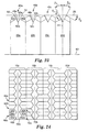
- Figs. 13-15 illustrate exemplary alternate embodiments lamina manufactured within the scope of the present disclosure.
- Fig. 13 shows a lamina 110 that includes an array of cube corner elements 160a, 160b, 160c, etc. (collectively referred to as 160) disposed in a first orientation and an array of cube corner elements 170a, 170b, 170c, etc. (collectively referred to as 170) disposed in a second orientation.
- the lamina 110 of Fig. 13 is characterized by the various groove sets being formed at angles that are not, in plan view, perpendicular to the reference plane 24.
- Lamina 110 can be formed either individually or as part of an assembly, as described above, by forming the first and second groove sets such that the respective reference edges are disposed in planes that intersect the third reference plane 28 at an oblique angle, ⁇ 1, and that intersect the second reference plane 26 at an orthogonal angle. Similarly, the third groove is formed along an axis that intersects first reference plane 24 at an oblique angle, ⁇ 1 . Additionally, the cube corner elements 160 are not aligned with the cube corner elements 170 on the lamina 110.
- Lamina 110 includes a plurality of cube corner elements having apertures of varying sizes and shapes. This variation in aperture size and shape may be desirable to accomplish certain optical objectives such as, for example, to enhance the uniformity of the retroreflection pattern of a retroreflective article formed as a replica of lamina 110.
- Fig. 14 shows a lamina 210 in which the third groove 246 is formed along an axis 216 that is parallel to but displaced from first reference plane 24. Additionally, the angles ⁇ 1 and ⁇ 2 differ from one another such that the symmetry axes of the respective opposing cube corner elements 214, 216 are canted at different angles relative to second reference plane 26.
- Fig. 15 shows a lamina 310 wherein the grooves A 1 , A 2 , A 3 , A 4 , A 5 in the first and/or second groove sets are formed with tools of varying included angles to yield a structured surface having a plurality of cube corner elements 312a, 312b, 312c, 312d, 312e and 312f of varying sizes and having varying included angles.
- the grooves A 1 , A 4 , A 5 can measure 90°
- groove A 2 measures 105°
- the groove A 3 measures 75°.
- the respective peaks and vertices of the cube corner elements 312 are disposed at varying distances from the bottom surface 318 of the lamina 310.
- Figs. 25-27 present a top plan view and side elevation views of the working surface of a lamina 410 that has an opposing pair of cube corner elements 460, 470 formed therein.
- Lamina 410 can be characterized in 3-dimensional space by reference planes 424, 426 and 428, as discussed above.
- cube corner element 460 can be defined as a unit cube having three substantially mutually perpendicular optical faces 432, 434, 448.
- Optical faces 432 and 434 are formed by opposing surfaces of parallel grooves 430a and 430b that intersect along a reference edge 436.
- Optical face 448 is formed by one surface of groove 446.
- Grooves 430a and 430b have respective vertices 433a and 433b that extend along axes that intersect third reference plane at an arbitrary angle ⁇ .
- groove 446 extends along an axis that intersects first reference plane at an arbitrary angle ⁇ .
- the angle ⁇ corresponds to the degree of angular rotation of the cube corner element on the surface of the lamina.
- the angle ⁇ can range from 0°, such that the groove sets are formed along axes substantially coincident with reference planes 424 and 428, to nearly 90°.
- ⁇ is between 0° and 45°.
- Fig. 26 presents a side elevation view of unit cube 460 taken along lines 26-26.
- a reference plane 456 is coincident with the vertex of groove 446 and is normal to second reference plane 426.
- Angle ⁇ 1 defines the acute angle between cube face 448 and reference plane 456.
- Groove vertices 433a and 433b are disposed at an acute angle ⁇ relative to second reference plane 426.
- Fig. 27 presents a side elevation view of unit cube 460 taken along lines 27-27. Planes 450a and 450b are coincident with the vertices 433a and 433b, respectively.
- the angle ⁇ 2 defines the acute angle between cube face 432 and reference plane 450a.
- the angle ⁇ 3 defines the acute angle between cube face 434 and reference plane 450b.
- a second cartesian coordinate system can be established using the groove vertices that form unit cube 460 as reference axes.
- the x-axis can be established parallel to the intersection of plane 456 and second reference plane 426.
- the y-axis can be established parallel to the intersection of plane 450b and second reference plane 426, and the z-axis extends perpendicular to second reference plane 426.
- any set of angles ⁇ 1 , ⁇ 2 , ⁇ 3 and ⁇ meeting this criteria will form retroreflective cube corner elements.
- a manufacturer of retroreflective cube corner sheeting can select a value for angle ⁇ 1 to orient the optical axis of the cube corner element at a desired angle relative to the base plane of the retroreflective sheeting formed as a replica of the mold.
- the present disclosure contemplates minor deviations from perfect orthogonality designed to alter the characteristics of the pattern of retroreflected light.
- the laminae are preferably formed from a dimensionally stable material capable of holding precision tolerances, such as machinable plastics (for example, polyethylene teraphthalate, polymethyl methacrylate, and polycarbonate) or metals (for example, brass, nickel, copper, or aluminum).
- machinable plastics for example, polyethylene teraphthalate, polymethyl methacrylate, and polycarbonate
- metals for example, brass, nickel, copper, or aluminum.
- the physical dimensions of the laminae are constrained primarily by machining limitations.
- the laminae preferably measure at least 0.1 millimeters in thickness. between 5.0 and 100.0 millimeters in height, and between 10 and 500 millimeters in width. These measurements are provided for illustrative purposes only and are not intended to be limiting.
- the structured surface of the plurality of laminae is used as a master mold which can be replicated using electroforming techniques or other conventional replicating technology.
- the plurality of laminae can include substantially identical cube corner elements or may include cube corner elements of varying sizes, geometries, or orientations.
- the structured surface of the replica referred to in the art as a 'stamper' contains a negative image of the cube corner elements.
- This replica can be used as a mold for forming a retroreflector. More commonly, however, a large number of positive or negative replicas are assembled to form a mold large enough to be useful in forming retroreflective sheeting.
- Retroreflective sheeting can then be manufactured as an integral material, e.g. by embossing a preformed sheet with an array of cube corner elements as described above or by casting a fluid material into a mold.
- the retroreflective sheeting can be manufactured as a layered product by casting the cube corner elements against a preformed film as taught in PCT application No. WO 95/11464 and U.S. Pat. No. 3,648,348 or by laminating a preformed film to preformed cube corner elements.
- such sheeting can be made using a nickel mold formed by electrolytic deposition of nickel onto a master mold.
- the electroformed mold can be used as a stamper to emboss the pattern of the mold onto a polycarbonate film approximately 500 ⁇ m thick having an index of refraction of about 1.59.
- the mold can be used in a press with the pressing performed at a temperature of approximately 175° to 200° C.
- Useful materials for making such reflective sheeting are preferably materials that are dimensionally stable, durable, weatherable and readily formable into the desired configuration.
- suitable materials include acrylics, which generally have an index of refraction of about 1.5, such as Plexiglas resin from Rohm and Haas; thermoset acrylates and epoxy acrylates, preferably radiation cured, polycarbonates, which have an index of refraction of about 1.6; polyethylene-based ionomers (marketed under the name 'SURLYN'); polyesters; and cellulose acetate butyrates.
- any optically transmissive material that is formable, typically under heat and pressure can be used.
- Other suitable materials for forming retroreflective sheeting are disclosed in U.S. Pat. No. 5,450,235 to Smith et al.
- the sheeting can also include colorants, dyes, UV absorbers, or other additives as needed.
- a backing layer is particularly useful for retroreflective sheeting that reflects light according to the principles of total internal reflection.
- a suitable backing layer can be made of any transparent or opaque material, including colored materials, that can be effectively engaged with the disclosed retroreflective sheeting.
- Suitable backing materials include aluminum sheeting, galvanized steel, polymeric materials such as polymethyl methacrylates, polyesters, polyamids, polyvinyl fluorides, polycarbonates, polyvinyl chlorides, polyurethanes, and a wide variety of laminates made from these and other materials.
- the backing layer or sheet can be sealed in a grid pattern or any other configuration suitable to the reflecting elements. Sealing can be affected by use of a number of methods including ultrasonic welding, adhesives, or by heat sealing at discrete locations on the arrays of reflecting elements (see, e.g. U.S. Pat. No. 3,924,928). Sealing is desirable to inhibit the entry of contaminants such as soil and/or moisture and to preserve air spaces adjacent the reflecting surfaces of the cube corner elements.
- backing sheets of polycarbonate, polybutryate or fiber-reinforced plastic can be used.
- the material may be rolled or cut into strips or other suitable designs.
- the retroreflective material can also be backed with an adhesive and a release sheet to render it useful for application to any substrate without the added step of applying an adhesive or using other fastening means.
- the cube corner elements disclosed herein can be individually tailored so as to distribute light retroreflected by the articles into a desired pattern or divergence profile, as taught by U.S. Pat. No. 4,775,219.
- the groove half-angle error introduced will be less than ⁇ 20 arc minutes and often less than ⁇ 5 arc minutes.
- a first groove set was formed by moving a diamond machining tool transversely across the plurality of laminae along axes substantially perpendicular to the major surfaces of the laminae.
- the grooves were uniformly formed to a depth of approximately 0.154 millimeters and the groove vertices were separated by a distance of approximately 0.308 millimeters.
- the plurality of laminae were then removed from the fixture and repositioned such that the first reference planes of the plurality of laminae were disposed at an angle of 27.8° from the reference axis.
- a second groove set was formed by moving a diamond machining tool transversely across the plurality of laminae along axes substantially perpendicular to the major surfaces of the laminae.
- the grooves were uniformly formed to a depth of approximately 0.154millimeters and the groove vertices were separated by a distance of approximately 0.308 millimeters. Additionally, the grooves were formed along axes substantially coplanar with the axes of corresponding grooves in the first groove set.
- the plurality of laminae were again removed from the fixture and were repositioned such that their respective first reference planes were substantially perpendicular to the base plane of the fixture.
- a third groove set was then formed by moving a diamond machining tool having a 55.6° included angle along an axis substantially coincident with the first reference plane of each lamina in the assembly.
- the laminae were then removed from the assembly, cleaned, and reassembled in a fixture to form a master tooling.
- a nickel stamper tool was formed from the surface of the master tooling using chemical vapor deposition of nickel.
- the reflection coefficient of a specular nickel surface for incandescent light is about 0.62 to about 0.64.
- the percentage light return was measured for the nickel stamper arranged at an orientation angle of about zero and an entrance angle of about -4°. The percentage light return data was adjusted to correspond to a circular area with a diameter of about 26.99 millimeters (1.0625 inches).
- the percentage light return was measured for a nickel stamper tool used to make retroflective sheeting with truncated cube corner elements according to U.S. Pat. No. 4,588,258 (Hoopman) having a base triangle of about 70°-55°-55°.
- the stamper tool was arranged at an orientation angle of about 180° and at an entrance angle of about -4°.
- the percentage light return data was for a circular area with a diameter of about 26.99 millimeters (1.0625 inches).
Landscapes
- Engineering & Computer Science (AREA)
- Manufacturing & Machinery (AREA)
- Ophthalmology & Optometry (AREA)
- Mechanical Engineering (AREA)
- Health & Medical Sciences (AREA)
- Optical Elements Other Than Lenses (AREA)
- Moulds For Moulding Plastics Or The Like (AREA)
- Laminated Bodies (AREA)
- Fixed Capacitors And Capacitor Manufacturing Machines (AREA)
- Heating, Cooling, Or Curing Plastics Or The Like In General (AREA)
- Blow-Moulding Or Thermoforming Of Plastics Or The Like (AREA)
- Adornments (AREA)
- Bending Of Plates, Rods, And Pipes (AREA)
Claims (25)
- Plättchen (10, 10a, 10b, 10c, 10d, 110, 210, 310, 410), das sich für die Verwendung in einer Form für die Verwendung bei der Formung retroreflektierender Würfeleckenartikel eignet, wobei das Plättchen eine erste und eine zweite Hauptoberfläche (12, 14) besitzt, die sich gegenüberliegen und zwischen sich eine erste Bezugsebene (24) definieren, wobei das Plättchen weiterhin eine verbindende Oberfläche (16) aufweist, die die erste und die zweite Hauptoberfläche miteinander verbindet, und folgendes aufweist:weiterhin gekennzeichnet durcheinen ersten Satz Nuten (30) einschließlich mindestens zweier paralleler, benachbarter, V-förmiger Nuten (30a, 30b, 30c, A1, A2, A3, A4, A5) in der verbindenden Oberfläche des Plättchens, die eine erste Nutenoberfläche und eine zweite Nutenoberfläche definieren, die sich im wesentlichen senkrecht zueinander schneiden und eine erste Bezugskante (36) bilden,
einen zweiten Satz Nuten (38) einschließlich mindestens zweier paralleler, benachbarter, V-förmiger Nuten (38a, 38b, 38c, A1, A2, A3, A4, A5) in der verbindenden Oberfläche des Plättchens, die eine dritte Nutenoberfläche und eine vierte Nutenoberfläche definieren, die sich im wesentlichen senkrecht zueinander schneiden und eine zweite Bezugskante (44) bilden, und
einen dritten Satz Nuten (46) einschließlich mindestens einer Nut (46) in der verbindenden Oberfläche des Plättchens, die eine fünfte Nutenoberfläche und eine sechste Nutenoberfläche definiert, wobei die fünfte Nutenoberfläche die erste und die zweite Nutenoberfläche im wesentlichen senkrecht schneidet und mindestens eine erste Würfelecke (60a, 60b, 160a, 160b, 160c, 214, 312a-f) bildet, die in einer ersten Ausrichtung angeordnet ist, und die sechste Nutenoberfläche die dritte und die vierte Nutenoberfläche im wesentlichen senkrecht schneidet und mindestens eine zweite Würfelecke (70a, 70b, 70c, 170a, 170b, 170c, 212, 312a-f) bildet, die in einer zweiten Ausrichtung angeordnet ist, die sich von der ersten Ausrichtung unterscheidet, und
wobei die mindestens eine erste Würfelecke mehrere nicht identische Würfeleckenelemente aufweist. - Plättchen nach Anspruch 1, wobei die verbindende Oberfläche eine zweite Bezugsebene (26) definiert, die im wesentlichen parallel zur verbindenden Oberfläche und senkrecht zur ersten Bezugsebene verläuft, und wobei die erste Bezugskante in Bezug auf die zweite Bezugsebene in einem ersten Winkel und die zweite Bezugskante in Bezug auf die zweite Bezugsebene in einem zweiten Winkel geneigt ist, der sich von dem ersten Winkel unterscheidet.
- Plättchen nach Anspruch 1, wobei der erste und/oder der zweite Satz Nuten in der verbindenden Oberfläche des Plättchens Nuten mit unterschiedlichen Tiefen aufweist.
- Plättchen nach Anspruch 1, wobei dem sich die fünfte und die sechste Nutenoberfläche schneiden und eine Nutenspitze definieren, die sich an einer Achse entlang erstreckt, die die erste Bezugsebene in einem schrägen Winkel schneidet.
- Plättchen nach Anspruch 1, wobei die verbindende Oberfläche eine zweite Bezugsebene (26) definiert, die im wesentlichen parallel zur verbindenden Oberfläche und senkrecht zur ersten Bezugsebene verläuft, und die erste und die zweite Nutenoberfläche in Bezug auf eine zur zweiten Bezugsebene senkrechte Achse in unterschiedlichen Winkeln geneigt sind.
- Plättchen nach Anspruch 1, wobei der erste und/oder der zweite Satz Nuten Nuten mit unterschiedlichen eingeschlossenen Winkeln aufweist.
- Plättchen nach Anspruch 1, wobei der dritte Satz Nuten im wesentlichen aus einer Nut besteht.
- Plättchen nach Anspruch 7, wobei sich die eine Nut an einer Achse entlang erstreckt, die im wesentlichen parallel zur ersten Bezugsebene ist.
- Plättchen nach Anspruch 1, wobei die erste und die zweite Hauptoberfläche im wesentlichen eben sind.
- Formbaugruppe, die mehrere Plättchen nach Anspruch 1 aufweist.
- Formbaugruppe nach Anspruch 10, wobei die Dicke jedes Plättchens zwischen etwa 0,025 und etwa 5 Millimeter beträgt.
- Retroreflektierendes Bahnenmaterial, das direkt oder indirekt aus der Formbaugruppe von Anspruch 10 hergestellt ist.
- Verfahren für die Herstellung eines Plättchens für die Verwendung in einer Form, die sich für die Verwendung bei der Formung retroreflektierender Würfeleckenartikel eignet, wobei das Plättchen eine erste und eine zweite Hauptoberfläche besitzt, die sich gegenüberliegen und zwischen sich eine erste Bezugsebene definieren, und wobei das Plättchen weiterhin eine verbindende Oberfläche aufweist, die die erste und die zweite Hauptoberfläche miteinander verbindet, wobei das Verfahren folgendes aufweist:weiterhin gekennzeichnet durchdas Formen eines ersten Satzes Nuten einschließlich mindestens zweier paralleler, benachbarter, V-förmiger Nuten in der verbindenden Oberfläche des Plättchens, die eine erste Nutenoberfläche und eine zweite Nutenoberfläche definieren, die sich im wesentlichen senkrecht zueinander schneiden und eine erste Bezugskante bilden,
das Formen eines zweiten Satzes Nuten einschließlich mindestens zweier paralleler, benachbarter, V-förmiger Nuten in der verbindenden Oberfläche des Plättchens, die eine dritte Nutenoberfläche und eine vierte Nutenoberfläche definieren, die sich im wesentlichen senkrecht zueinander schneiden und eine zweite Bezugskante bilden, und
das Formen eines dritten Satzes Nuten einschließlich mindestens einer Nut in der verbindenden Oberfläche des Plättchens, die eine fünfte Nutenoberfläche und eine sechste Nutenoberfläche definiert, wobei die fünfte Nutenoberfläche die erste und die zweite Nutenoberfläche im wesentlichen senkrecht schneidet und mindestens eine erste Würfelecke bildet, die in einer ersten Ausrichtung angeordnet ist, und die sechste Nutenoberfläche die dritte und die vierte Nutenoberfläche im wesentlichen senkrecht schneidet und mindestens eine zweite Würfelecke bildet, die in einer zweiten Ausrichtung angeordnet ist, die sich von der ersten Ausrichtung unterscheidet, und
wobei der erste Satz Nuten mit einer ersten Ausrichtung des Plättchens geformt wird, der zweite Satz Nuten mit einer zweiten Ausrichtung des Plättchens geformt wird und der dritte Satz Nuten mit einer dritten Ausrichtung des Plättchens geformt wird, die sich von der ersten oder zweiten Ausrichtung unterscheidet. - Verfahren für die Herstellung eines Plättchens für die Verwendung in einer Form, die sich für die Verwendung bei der Formung retroreflektierender Würfeleckenartikel eignet, wobei das Plättchen eine erste und eine zweite Hauptoberfläche besitzt, die sich gegenüberliegen und zwischen sich eine erste Bezugsebene definieren, und wobei das Plättchen weiterhin eine verbindende Oberfläche aufweist, die die erste und die zweite Hauptoberfläche miteinander verbindet, wobei das Verfahren folgendes aufweist:weiterhin gekennzeichnet durchdas Formen eines ersten Satzes Nuten einschließlich mindestens zweier paralleler, benachbarter, V-förmiger Nuten in der verbindenden Oberfläche des Plättchens, die eine erste Nutenoberfläche und eine zweite Nutenoberfläche definieren, die sich im wesentlichen senkrecht zueinander schneiden und eine erste Bezugskante bilden,
das Formen eines zweiten Satzes Nuten einschließlich mindestens zweier paralleler, benachbarter, V-förmiger Nuten in der verbindenden Oberfläche des Plättchens, die eine dritte Nutenoberfläche und eine vierte Nutenoberfläche definieren, die sich im wesentlichen senkrecht zueinander schneiden und eine zweite Bezugskante bilden, und
das Formen eines dritten Satzes Nuten einschließlich mindestens einer Nut in der verbindenden Oberfläche des Plättchens, die eine fünfte Nutenoberfläche und eine sechste Nutenoberfläche definiert, wobei die fünfte Nutenoberfläche die erste und die zweite Nutenoberfläche im wesentlichen senkrecht schneidet und mindestens eine erste Würfelecke bildet, die in einer ersten Ausrichtung angeordnet ist, und die sechste Nutenoberfläche die dritte und die vierte Nutenoberfläche im wesentlichen senkrecht schneidet und mindestens eine zweite Würfelecke bildet, die in einer zweiten Ausrichtung angeordnet ist, die sich von der ersten Ausrichtung unterscheidet, und
wobei der erste, der zweite und der dritte Satz Nuten bei in einer übereinstimmenden Position angeordnetem Plättchen geformt werden. - Verfahren nach Anspruch 13 oder 14, wobei mindestens einer der Formschritte das Formen von Nuten mit verschiedenen Tiefen in der verbindenden Oberfläche aufweist.
- Verfahren nach Anspruch 13 oder 14, wobei die verbindende Oberfläche eine zweite Bezugsebene (26) definiert, die im wesentlichen parallel zur verbindenden Oberfläche und senkrecht zur ersten Bezugsebene verläuft, und wobei bei dem Schritt des Formens des ersten Satzes Nuten die Nuten derart geformt werden, daß die erste Bezugskante in Bezug auf die zweite Bezugsebene in einem ersten Winkel geneigt ist, und bei dem Schritt des Formens des zweiten Satzes Nuten die Nuten derart geformt werden, daß die zweite Bezugskante in Bezug auf die zweite Bezugsebene in einem zweiten Winkel geneigt ist, der sich von dem ersten Winkel unterscheidet.
- Verfahren nach Anspruch 13, wobei das Plättchen eines von mehreren Plättchen ist, wobei jedes Plättchen eine erste und eine zweite Hauptoberfläche besitzt, die sich gegenüberliegen und zwischen sich eine erste Bezugsebene definieren, und wobei jedes Plättchen weiterhin eine verbindende Oberfläche aufweist, die die erste und die zweite Hauptoberfläche miteinander verbindet,
wobei der Schritt des Formens des ersten Satzes Nuten das Formen des ersten Satzes Nuten in der verbindenden Oberfläche jedes Plättchens aufweist, nachdem die mehreren Plättchen derart ausgerichtet worden sind, daß ihre jeweiligen ersten Bezugsebenen parallel zueinander und in Bezug auf eine feste Bezugsachse in einem ersten Winkel angeordnet sind,
wobei der Schritt des Formens des zweiten Satzes Nuten das Formen des zweiten Satzes Nuten in der verbindenden Oberfläche jedes Plättchens aufweist, nachdem die mehreren Plättchen derart ausgerichtet worden sind, daß ihre jeweiligen ersten Bezugsebenen parallel zueinander und in Bezug auf die feste Bezugsachse in einem zweiten Winkel angeordnet sind, und
wobei der Schritt des Formens des dritten Satzes Nuten das Formen des dritten Satzes Nuten in der verbindenden Oberfläche der mehreren Plättchen aufweist. - Verfahren nach Anspruch 17, das weiterhin vor dem Schritt des Formens des dritten Satzes Nuten den Schritt des derartigen Ausrichtens der mehreren Plättchen aufweist, daß ihre jeweiligen ersten Bezugsebenen parallel zueinander und in Bezug auf die feste Bezugsachse in einem dritten Winkel angeordnet sind.
- Verfahren nach Anspruch 17, wobei mindestens einer der Formschritte das Formen von Nuten in verschiedenen Tiefen in der verbindenden Oberfläche der Plättchen aufweist.
- Verfahren nach Anspruch 17, wobei mindestens einer der Formschritte das Formen von Nuten mit ungleichmäßigem Nutenabstand in der verbindenden Oberfläche der Plättchen aufweist.
- Verfahren nach Anspruch 17, wobei der Schritt des Formens eines dritten Satzes Nuten das derartige Formen jeder Nut in dem dritten Satz Nuten aufweist, daß sich die fünfte Nutenoberfläche und die sechste Nutenoberfläche an einer Achse entlang schneiden, die die erste Bezugsebene in einem schrägen Winkel schneidet.
- Verfahren nach Anspruch 17, wobei sich die mindestens eine erste und die mindestens eine zweite Würfelecke jeweils im wesentlichen auf einem der Plättchen befinden.
- Verfahren nach Anspruch 17, wobei benachbarte erste und zweite Hauptoberflächen eine im wesentlichen ebene Grenzfläche aufweisen.
- Mehrere Plättchen, die nach dem Verfahren von Anspruch 17 hergestellt sind.
- Verfahren nach Anspruch 17, das weiterhin das Replizieren der verbindenden Oberfläche der mehreren Plättchen in einem integralen Substrat aufweist, um eine Negativkopie der mehreren Würfeleckenelemente zu formen, die sich für die Verwendung als Form für die Formung retroreflektierender Artikel eignet.
Applications Claiming Priority (3)
| Application Number | Priority Date | Filing Date | Title |
|---|---|---|---|
| US88607497A | 1997-07-02 | 1997-07-02 | |
| US886074 | 1997-07-02 | ||
| PCT/US1998/012459 WO1999001275A1 (en) | 1997-07-02 | 1998-06-12 | Cube corner sheeting mold and method of making the same |
Publications (2)
| Publication Number | Publication Date |
|---|---|
| EP1017557A1 EP1017557A1 (de) | 2000-07-12 |
| EP1017557B1 true EP1017557B1 (de) | 2004-12-08 |
Family
ID=25388319
Family Applications (1)
| Application Number | Title | Priority Date | Filing Date |
|---|---|---|---|
| EP98930255A Expired - Lifetime EP1017557B1 (de) | 1997-07-02 | 1998-06-12 | Form für würfeleckenbahnen und verfahren zu deren herstellung |
Country Status (14)
| Country | Link |
|---|---|
| US (3) | US6257860B1 (de) |
| EP (1) | EP1017557B1 (de) |
| JP (1) | JP4235750B2 (de) |
| KR (1) | KR100573526B1 (de) |
| CN (1) | CN1105637C (de) |
| AT (1) | ATE284306T1 (de) |
| AU (1) | AU728328B2 (de) |
| BR (1) | BR9810229A (de) |
| CA (1) | CA2294762A1 (de) |
| DE (1) | DE69828070T2 (de) |
| IL (1) | IL133857A0 (de) |
| NO (1) | NO996562L (de) |
| TR (1) | TR199903340T2 (de) |
| WO (1) | WO1999001275A1 (de) |
Families Citing this family (38)
| Publication number | Priority date | Publication date | Assignee | Title |
|---|---|---|---|---|
| US6015214A (en) * | 1996-05-30 | 2000-01-18 | Stimsonite Corporation | Retroreflective articles having microcubes, and tools and methods for forming microcubes |
| US6253442B1 (en) * | 1997-07-02 | 2001-07-03 | 3M Innovative Properties Company | Retroreflective cube corner sheeting mold and method for making the same |
| TR199903340T2 (xx) | 1997-07-02 | 2001-06-21 | Minnesota Mining & Manufacturing Company | K�p k��eli kaplama/Z�rh kal�b� ve bunun imaline y�nelik metod. |
| US6540367B1 (en) | 1999-04-07 | 2003-04-01 | 3M Innovative Properties Company | Structured surface articles containing geometric structures with compound faces and methods for making same |
| US8728610B2 (en) | 2000-02-25 | 2014-05-20 | 3M Innovative Properties Company | Compound mold and structured surface articles containing geometric structures with compound faces and method of making same |
| US6700712B2 (en) | 2001-11-13 | 2004-03-02 | 3M Innovative Properties Company | Multidirectional single surface optically shaped film |
| DE10216579A1 (de) * | 2002-04-14 | 2003-10-23 | Sen Hans-Erich Gubela | Weitwinkelsensorsystem mit Tripelreflektor und Herstellung der Werkzeuge |
| AU2002316268A1 (en) * | 2002-06-11 | 2003-12-22 | 3M Innovative Properties Company | Methods of making a master and replicas thereof |
| EP2442154A3 (de) * | 2003-03-06 | 2012-05-09 | 3M Innovative Properties Co. | Schicht mit würfeleckförmigen Elementen und retroreflektive Folie |
| US6884371B2 (en) * | 2003-03-06 | 2005-04-26 | 3M Innovative Properties Company | Method of making retroreflective sheeting and articles |
| US7174619B2 (en) | 2003-03-06 | 2007-02-13 | 3M Innovative Properties Company | Methods of making microstructured lamina and apparatus |
| US7156527B2 (en) | 2003-03-06 | 2007-01-02 | 3M Innovative Properties Company | Lamina comprising cube corner elements and retroreflective sheeting |
| US7201485B1 (en) * | 2003-08-15 | 2007-04-10 | University Of South Florida | Corner cube retroreflector |
| US7677146B2 (en) * | 2006-05-10 | 2010-03-16 | 3M Innovative Properties Company | Cutting tool using one or more machined tool tips in a continuous or interrupted cut fast tool servo |
| US8215943B2 (en) * | 2006-06-01 | 2012-07-10 | Avery Dennison Corporation | Heat-transfer label assembly and apparatus for applying heat-transfer labels |
| US8459806B2 (en) | 2006-08-22 | 2013-06-11 | Nippon Carbide Kogyo Kabushiki Kaisha | Triangular pyramid type cube corner retroreflection article, and its manufacturing method |
| US7628100B2 (en) * | 2007-01-05 | 2009-12-08 | 3M Innovative Properties Company | Cutting tool using one or more machined tool tips with diffractive features in a continuous or interrupted cut fast tool servo |
| US7506987B2 (en) * | 2007-03-02 | 2009-03-24 | Technology Solutions & Invention Llc | Two-sided corner-cube retroreflectors and methods of manufacturing the same |
| EP2192426A4 (de) * | 2007-08-24 | 2012-05-23 | Nippon Carbide Kogyo Kk | Würfeleckenretroreflektiver artikel |
| US7669508B2 (en) * | 2007-10-29 | 2010-03-02 | 3M Innovative Properties Company | Cutting tool using one or more machined tool tips with diffractive features |
| US20090147361A1 (en) * | 2007-12-07 | 2009-06-11 | 3M Innovative Properties Company | Microreplicated films having diffractive features on macro-scale features |
| US9810817B2 (en) * | 2008-04-02 | 2017-11-07 | 3M Innovative Properties Company | Light directing film and method for making the same |
| US20110181971A1 (en) * | 2008-04-02 | 2011-07-28 | Campbell Alan B | Methods and systems for fabricating optical films having superimposed features |
| BRPI0914453B1 (pt) * | 2008-10-22 | 2020-02-18 | 3M Innovative Properties Company | Laminação retrorrefletiva e método de produção de uma laminação retrorrefletiva |
| DE112010003508B4 (de) | 2009-09-01 | 2022-02-03 | Dbm Reflex Enterprises Inc. | Vielfarbenfahrzeuglinse mit wechselseitig verbundenen TIR-Reflexionsprismen und Spritzgussvorrichtung |
| EP2518504A1 (de) | 2011-04-29 | 2012-10-31 | Miltenyi Biotec GmbH | Verfahren zur quantitativen und qualitativen Charakterisierung von antigenspezifischen T-Zellen, die ein spezifischen Antigen erkennen |
| WO2012166462A2 (en) | 2011-05-31 | 2012-12-06 | 3M Innovative Properties Company | Method for making microstructured tools having interspersed topographies, and articles produced therefrom |
| WO2012166448A1 (en) | 2011-05-31 | 2012-12-06 | 3M Innovative Properties Company | Retroreflective articles having composite cube-corners and methods of making |
| BR112013030706A2 (pt) | 2011-05-31 | 2016-12-06 | 3M Innovative Properties Co | métodos de fabricação de artigos microestruturados curados com padrão diferencialmente |
| CN104838293A (zh) * | 2012-12-28 | 2015-08-12 | 未来奈米科技股份有限公司 | 利用变形结构立方角的反光片 |
| SG11201507627YA (en) | 2013-03-15 | 2015-10-29 | 3M Innovative Properties Co | Microtiled prismatic cube corner articles |
| US20160011346A1 (en) | 2014-07-14 | 2016-01-14 | Sergiy Vasylyev | High incidence angle retroreflective sheeting |
| EP3348389B1 (de) | 2014-11-20 | 2023-09-27 | Avery Dennison Corporation | Geflieste artikel und verfahren zur herstellung gefliester artikel |
| CN106238582B (zh) * | 2016-09-19 | 2017-12-08 | 哈尔滨工业大学 | 一种采用金属箔材/薄板制造空间可展开舱段的模具 |
| EP3583453A4 (de) | 2017-02-14 | 2021-03-10 | 3M Innovative Properties Company | Sicherheitsartikel mit gruppen von mikrostrukturen, die durch endfräsen hergestellt werden |
| TWI756466B (zh) | 2017-08-29 | 2022-03-01 | 美商艾維利 丹尼森公司 | 用於基於投影機的顯示系統的回射片 |
| KR102404055B1 (ko) | 2017-09-11 | 2022-05-30 | 오라폴 아메리카스 인코포레이티드 | 다각형 개구로 역반사기 프리즘을 제조하는 방법 및 그 장치 |
| WO2022046134A1 (en) | 2020-08-27 | 2022-03-03 | Aura Optical System, LP | Microprismatic retroreflective mold, sheet, and article and methods of manufacture thereof |
Family Cites Families (70)
| Publication number | Priority date | Publication date | Assignee | Title |
|---|---|---|---|---|
| US835648A (en) | 1906-03-13 | 1906-11-13 | Zeiss Carl Fa | Reflector. |
| US1591572A (en) * | 1925-02-05 | 1926-07-06 | Jonathan C Stimson | Process and apparatus for making central triple reflectors |
| US1906655A (en) | 1928-11-03 | 1933-05-02 | Stimson Jonathan Cass | Process and apparatus for making reflecting devices |
| US2205638A (en) | 1938-01-03 | 1940-06-25 | Jonathan C Stimson | Reflecting device |
| US2538638A (en) | 1939-07-17 | 1951-01-16 | Wilson Herbert Frederick | Mold for making reflectors |
| US2723595A (en) | 1951-12-26 | 1955-11-15 | Rupert Richard | Reflecting device |
| US3069721A (en) | 1960-03-04 | 1962-12-25 | Ciba Ltd | Tools for making surface patterns |
| FR1289029A (fr) | 1961-04-17 | 1962-03-30 | Perfectionnement à l'obtention de pièces moulées à surfaces optiques | |
| US3190178A (en) | 1961-06-29 | 1965-06-22 | Minnesota Mining & Mfg | Reflex-reflecting sheeting |
| US3277535A (en) | 1963-10-21 | 1966-10-11 | Continental Reflectors Inc | Molding apparatus for reflecting devices |
| US3363875A (en) | 1963-12-05 | 1968-01-16 | Hedgewick Peter | Molding apparatus for reflectors |
| US3417959A (en) | 1966-11-14 | 1968-12-24 | Minnesota Mining & Mfg | Die for forming retro-reflective article |
| US4208090A (en) | 1967-03-24 | 1980-06-17 | Amerace Corporation | Reflector structure |
| US3443281A (en) | 1967-07-24 | 1969-05-13 | Rupert Mfg Co | Molding pin,matrix,and molding assembly for manufacture of reflective devices |
| US3541606A (en) | 1967-10-16 | 1970-11-17 | Amerace Esna Corp | Reflectorized vehicles and reflectors therefor |
| US3922065A (en) | 1968-05-31 | 1975-11-25 | Minnesota Mining & Mfg | Cube-corner retro-reflective article |
| DE1917292A1 (de) | 1969-04-03 | 1970-10-15 | Hans Hillesheim | Formteil mit reflektierenden Prismen und Form zur Herstellung derselben |
| US3649153A (en) | 1969-11-04 | 1972-03-14 | Peter E Brudy | Faceted core |
| US3632695A (en) | 1970-03-05 | 1972-01-04 | Reflex Corp Canada Ltd | Making a combined lens and reflector |
| US3899154A (en) | 1970-09-05 | 1975-08-12 | Ichikoh Industries Ltd | Light reflector mold |
| US3684348A (en) | 1970-09-29 | 1972-08-15 | Rowland Dev Corp | Retroreflective material |
| US3810804A (en) | 1970-09-29 | 1974-05-14 | Rowland Dev Corp | Method of making retroreflective material |
| US3712706A (en) | 1971-01-04 | 1973-01-23 | American Cyanamid Co | Retroreflective surface |
| US3873184A (en) | 1973-02-16 | 1975-03-25 | Amerace Esna Corp | Reflector with interspersed angled reflex elements |
| US3926402A (en) | 1973-04-24 | 1975-12-16 | Amerace Corp | Pin having nonaligned cube axis and pin axis and bundle of such pins |
| US3923378A (en) | 1973-04-24 | 1975-12-02 | Amerace Corp | Cube-corner reflector with non-aligned cube axes and element axes |
| US3948714A (en) | 1973-05-23 | 1976-04-06 | Firma Hans Gubela | Large-area reflectors from plastics |
| USRE29396E (en) | 1975-02-18 | 1977-09-13 | Amerace Corporation | Pin having nonaligned cube axis and pin axis and bundle of such pins |
| US3924928A (en) | 1975-03-12 | 1975-12-09 | Robert C Trimble | Attachment for reflectors for spoke wheels |
| US4025159A (en) | 1976-02-17 | 1977-05-24 | Minnesota Mining And Manufacturing Company | Cellular retroreflective sheeting |
| US4066236A (en) | 1976-06-25 | 1978-01-03 | Beatrice Foods Co. | Cube corner type retroreflector bodies and molds made therewith |
| US4066331A (en) | 1976-06-25 | 1978-01-03 | Beatrice Foods Co. | Cube corner type retroreflectors with improved cube corner unit relationships |
| US4095773A (en) | 1976-11-18 | 1978-06-20 | Beatrice Foods Co. | Subassemblies for cube corner type retroreflector molds |
| US4601861A (en) | 1982-09-30 | 1986-07-22 | Amerace Corporation | Methods and apparatus for embossing a precision optical pattern in a resinous sheet or laminate |
| US5156863A (en) * | 1982-09-30 | 1992-10-20 | Stimsonite Corporation | Continuous embossing belt |
| US4478769A (en) | 1982-09-30 | 1984-10-23 | Amerace Corporation | Method for forming an embossing tool with an optically precise pattern |
| US4588258A (en) | 1983-09-12 | 1986-05-13 | Minnesota Mining And Manufacturing Company | Cube-corner retroreflective articles having wide angularity in multiple viewing planes |
| IT8383524A0 (it) | 1983-12-27 | 1983-12-27 | Seima Italiana Spa | Barrette per catadiottri. |
| US4775219A (en) * | 1986-11-21 | 1988-10-04 | Minnesota Mining & Manufacturing Company | Cube-corner retroreflective articles having tailored divergence profiles |
| US5066098A (en) | 1987-05-15 | 1991-11-19 | Minnesota Mining And Manufacturing Company | Cellular encapsulated-lens high whiteness retroreflective sheeting with flexible cover sheet |
| US5138488A (en) | 1990-09-10 | 1992-08-11 | Minnesota Mining And Manufacturing Company | Retroreflective material with improved angularity |
| US5300263A (en) | 1992-10-28 | 1994-04-05 | Minnesota Mining And Manufacturing Company | Method of making a microlens array and mold |
| DE4236799C2 (de) * | 1992-10-30 | 1994-09-08 | Gubela Sen Hans Erich | Verfahren zur Herstellung eines Abformwerkzeuges mit einer würfelstrukturförmigen Oberfläche zum Herstellen von Hochleistungs-Tripel-Reflektoren |
| DE4410994C2 (de) | 1992-10-30 | 1996-01-25 | Gubela Sen Hans Erich | Körper oder Bauteil eines strangförmigen Tripelreflektors und Werkzeugelement zur Abformung von Tripelreflektoren |
| DE4240680C2 (de) | 1992-12-03 | 1996-12-19 | Gubela Sen Hans Erich | Aus einer Vielzahl von Mikrotripeln bestehende Rückstrahlerfläche |
| DE9217179U1 (de) | 1992-12-16 | 1993-04-22 | Gubela Sen., Hans-Erich, 77871 Renchen | Mikrodoppeltripel-Flächen |
| WO1994018581A1 (de) | 1993-01-30 | 1994-08-18 | Kernforschungszentrum Karlsruhe Gmbh | Abformwerkzeug, verfahren zu dessen herstellung und tripelspiegel |
| US5600484A (en) | 1993-10-20 | 1997-02-04 | Minnesota Mining And Manufacturing Company | Machining techniques for retroreflective cube corner article and method of manufacture |
| KR100437958B1 (ko) | 1993-10-20 | 2004-08-25 | 미네소타 마이닝 앤드 매뉴팩춰링 캄파니 | 초가요성,역반사성입방체모서리를지닌복합시트및이의제조방법 |
| US5450235A (en) | 1993-10-20 | 1995-09-12 | Minnesota Mining And Manufacturing Company | Flexible cube-corner retroreflective sheeting |
| CA2173148A1 (en) | 1993-10-20 | 1995-04-27 | Kenneth L. Smith | Multiple structure cube corner article and method of manufacture |
| US5585164A (en) | 1993-10-20 | 1996-12-17 | Minnesota Mining And Manufacturing Company | Dual groove set retroreflective cube corner article and method of manufacture |
| CA2173231A1 (en) | 1993-10-20 | 1995-04-27 | Gerald M. Benson | Asymetric cube corner article and method of manufacture |
| US5691846A (en) | 1993-10-20 | 1997-11-25 | Minnesota Mining And Manufacturing Company | Ultra-flexible retroreflective cube corner composite sheetings and methods of manufacture |
| US5512219A (en) | 1994-06-03 | 1996-04-30 | Reflexite Corporation | Method of casting a microstructure sheet having an array of prism elements using a reusable polycarbonate mold |
| DE4429683C1 (de) | 1994-08-22 | 1996-03-21 | Gubela Sen Hans Erich | Körper oder Bauteil eines strangförmigen Tripelreflektors und/ oder Werkzeugelements zur Abformung von Tripelreflektoren |
| US5565151A (en) | 1994-09-28 | 1996-10-15 | Reflexite Corporation | Retroreflective prism structure with windows formed thereon |
| JPH08309851A (ja) | 1995-05-17 | 1996-11-26 | Idemitsu Petrochem Co Ltd | エンボスパターンを有する面状熱可塑性樹脂の製造方法及び装置 |
| CA2224095C (en) | 1995-06-09 | 2007-03-27 | Kenneth L. Smith | Tiled retroreflective sheeting |
| US6010609A (en) | 1995-07-28 | 2000-01-04 | Nippon Carside Kogyo Kabushiki Kaisha | Method of making a microprism master mold |
| CN1106252C (zh) | 1995-07-28 | 2003-04-23 | 日本电石工业株式会社 | 微棱镜母型 |
| US6159407A (en) | 1996-01-26 | 2000-12-12 | 3M Innovative Properties Company | Stacked laminate mold and method of making |
| JP2000504281A (ja) * | 1996-01-26 | 2000-04-11 | ミネソタ マイニング アンド マニュファクチャリング カンパニー | 積層ラミネート成形型およびその製法 |
| US6015214A (en) * | 1996-05-30 | 2000-01-18 | Stimsonite Corporation | Retroreflective articles having microcubes, and tools and methods for forming microcubes |
| US5734501A (en) | 1996-11-01 | 1998-03-31 | Minnesota Mining And Manufacturing Company | Highly canted retroreflective cube corner article |
| DE29701903U1 (de) | 1997-02-04 | 1997-03-27 | IMOS Gubela GmbH, 77871 Renchen | Meßtechnikretroflektor |
| TR199903340T2 (xx) * | 1997-07-02 | 2001-06-21 | Minnesota Mining & Manufacturing Company | K�p k��eli kaplama/Z�rh kal�b� ve bunun imaline y�nelik metod. |
| US5981032A (en) | 1997-07-02 | 1999-11-09 | 3M Innovative Properties Company | Retroreflective cube corner sheeting mold and sheeting formed therefrom |
| US6253442B1 (en) | 1997-07-02 | 2001-07-03 | 3M Innovative Properties Company | Retroreflective cube corner sheeting mold and method for making the same |
| US5898523A (en) | 1997-07-02 | 1999-04-27 | Minnesota Mining & Manufacturing Company | Tiled retroreflective sheeting composed of highly canted cube corner elements |
-
1998
- 1998-06-12 TR TR1999/03340T patent/TR199903340T2/xx unknown
- 1998-06-12 DE DE69828070T patent/DE69828070T2/de not_active Expired - Lifetime
- 1998-06-12 JP JP50718499A patent/JP4235750B2/ja not_active Expired - Lifetime
- 1998-06-12 WO PCT/US1998/012459 patent/WO1999001275A1/en active IP Right Grant
- 1998-06-12 CA CA002294762A patent/CA2294762A1/en not_active Abandoned
- 1998-06-12 IL IL133857A patent/IL133857A0/xx unknown
- 1998-06-12 EP EP98930255A patent/EP1017557B1/de not_active Expired - Lifetime
- 1998-06-12 CN CN98808612A patent/CN1105637C/zh not_active Expired - Lifetime
- 1998-06-12 AT AT98930255T patent/ATE284306T1/de not_active IP Right Cessation
- 1998-06-12 BR BR9810229-0A patent/BR9810229A/pt not_active IP Right Cessation
- 1998-06-12 AU AU79689/98A patent/AU728328B2/en not_active Ceased
- 1998-06-12 KR KR1019997012598A patent/KR100573526B1/ko not_active IP Right Cessation
-
1999
- 1999-12-29 NO NO996562A patent/NO996562L/no not_active Application Discontinuation
-
2000
- 2000-08-09 US US09/636,730 patent/US6257860B1/en not_active Expired - Lifetime
- 2000-08-09 US US09/636,520 patent/US6318987B1/en not_active Expired - Lifetime
-
2001
- 2001-09-27 US US09/965,389 patent/US6386855B1/en not_active Expired - Lifetime
Also Published As
| Publication number | Publication date |
|---|---|
| CA2294762A1 (en) | 1999-01-14 |
| US20020028263A1 (en) | 2002-03-07 |
| US6386855B1 (en) | 2002-05-14 |
| IL133857A0 (en) | 2001-04-30 |
| AU7968998A (en) | 1999-01-25 |
| WO1999001275A1 (en) | 1999-01-14 |
| CN1105637C (zh) | 2003-04-16 |
| US6257860B1 (en) | 2001-07-10 |
| CN1268921A (zh) | 2000-10-04 |
| KR20010014414A (ko) | 2001-02-26 |
| BR9810229A (pt) | 2000-08-08 |
| TR199903340T2 (xx) | 2001-06-21 |
| AU728328B2 (en) | 2001-01-04 |
| NO996562L (no) | 2000-03-01 |
| DE69828070T2 (de) | 2005-12-08 |
| US6318987B1 (en) | 2001-11-20 |
| JP2002507945A (ja) | 2002-03-12 |
| DE69828070D1 (de) | 2005-01-13 |
| ATE284306T1 (de) | 2004-12-15 |
| JP4235750B2 (ja) | 2009-03-11 |
| EP1017557A1 (de) | 2000-07-12 |
| KR100573526B1 (ko) | 2006-04-26 |
| NO996562D0 (no) | 1999-12-29 |
Similar Documents
| Publication | Publication Date | Title |
|---|---|---|
| EP1017557B1 (de) | Form für würfeleckenbahnen und verfahren zu deren herstellung | |
| US6447878B1 (en) | Retroreflective cube corner sheeting mold and sheeting formed therefrom | |
| US6253442B1 (en) | Retroreflective cube corner sheeting mold and method for making the same | |
| US6533887B1 (en) | Retroreflective cube corner sheeting, molds therefore, and methods of making the same | |
| EP0991963B1 (de) | Mosaikartige retroreflektierende folie bestehend aus stark verkanteten würfeleckigen elementen | |
| EP0724735B1 (de) | Direktmechanisch hergestellter stufenstrukturierter retroreflektiver würfelecken-körper und herstellungsverfahren | |
| MXPA00000089A (en) | Cube corner sheeting mold and method of making the same | |
| MXPA00000092A (en) | Retroreflective cube corner sheeting mold, lamina for creating such a mold and method for manufacturing such a lamina | |
| MXPA00000091A (en) | Method of manufacturing a plurality of laminae for use in a mold for forming retroreflective cube corner articles, mold and articles formed therewith |
Legal Events
| Date | Code | Title | Description |
|---|---|---|---|
| PUAI | Public reference made under article 153(3) epc to a published international application that has entered the european phase |
Free format text: ORIGINAL CODE: 0009012 |
|
| 17P | Request for examination filed |
Effective date: 20000127 |
|
| AK | Designated contracting states |
Kind code of ref document: A1 Designated state(s): AT BE CH CY DE DK ES FI FR GB GR IE IT LI LU MC NL PT SE |
|
| AX | Request for extension of the european patent |
Free format text: AL PAYMENT 20000127;LT PAYMENT 20000127;LV PAYMENT 20000127;MK PAYMENT 20000127;RO PAYMENT 20000127;SI PAYMENT 20000127 |
|
| 17Q | First examination report despatched |
Effective date: 20001107 |
|
| GRAP | Despatch of communication of intention to grant a patent |
Free format text: ORIGINAL CODE: EPIDOSNIGR1 |
|
| GRAS | Grant fee paid |
Free format text: ORIGINAL CODE: EPIDOSNIGR3 |
|
| GRAA | (expected) grant |
Free format text: ORIGINAL CODE: 0009210 |
|
| AK | Designated contracting states |
Kind code of ref document: B1 Designated state(s): AT BE CH CY DE DK ES FI FR GB GR IE IT LI LU MC NL PT SE |
|
| AX | Request for extension of the european patent |
Extension state: AL LT LV MK RO SI |
|
| PG25 | Lapsed in a contracting state [announced via postgrant information from national office to epo] |
Ref country code: NL Free format text: LAPSE BECAUSE OF FAILURE TO SUBMIT A TRANSLATION OF THE DESCRIPTION OR TO PAY THE FEE WITHIN THE PRESCRIBED TIME-LIMIT Effective date: 20041208 Ref country code: LI Free format text: LAPSE BECAUSE OF FAILURE TO SUBMIT A TRANSLATION OF THE DESCRIPTION OR TO PAY THE FEE WITHIN THE PRESCRIBED TIME-LIMIT Effective date: 20041208 Ref country code: IT Free format text: LAPSE BECAUSE OF FAILURE TO SUBMIT A TRANSLATION OF THE DESCRIPTION OR TO PAY THE FEE WITHIN THE PRE;WARNING: LAPSES OF ITALIAN PATENTS WITH EFFECTIVE DATE BEFORE 2007 MAY HAVE OCCURRED AT ANY TIME BEFORE 2007. THE CORRECT EFFECTIVE DATE MAY BE DIFFERENT FROM THE ONE RECORDED.SCRIBED TIME-LIMIT Effective date: 20041208 Ref country code: FR Free format text: LAPSE BECAUSE OF FAILURE TO SUBMIT A TRANSLATION OF THE DESCRIPTION OR TO PAY THE FEE WITHIN THE PRESCRIBED TIME-LIMIT Effective date: 20041208 Ref country code: FI Free format text: LAPSE BECAUSE OF FAILURE TO SUBMIT A TRANSLATION OF THE DESCRIPTION OR TO PAY THE FEE WITHIN THE PRESCRIBED TIME-LIMIT Effective date: 20041208 Ref country code: CH Free format text: LAPSE BECAUSE OF FAILURE TO SUBMIT A TRANSLATION OF THE DESCRIPTION OR TO PAY THE FEE WITHIN THE PRESCRIBED TIME-LIMIT Effective date: 20041208 Ref country code: BE Free format text: LAPSE BECAUSE OF FAILURE TO SUBMIT A TRANSLATION OF THE DESCRIPTION OR TO PAY THE FEE WITHIN THE PRESCRIBED TIME-LIMIT Effective date: 20041208 Ref country code: AT Free format text: LAPSE BECAUSE OF FAILURE TO SUBMIT A TRANSLATION OF THE DESCRIPTION OR TO PAY THE FEE WITHIN THE PRESCRIBED TIME-LIMIT Effective date: 20041208 |
|
| REG | Reference to a national code |
Ref country code: GB Ref legal event code: FG4D |
|
| REG | Reference to a national code |
Ref country code: CH Ref legal event code: EP |
|
| REG | Reference to a national code |
Ref country code: IE Ref legal event code: FG4D |
|
| REF | Corresponds to: |
Ref document number: 69828070 Country of ref document: DE Date of ref document: 20050113 Kind code of ref document: P |
|
| PG25 | Lapsed in a contracting state [announced via postgrant information from national office to epo] |
Ref country code: SE Free format text: LAPSE BECAUSE OF FAILURE TO SUBMIT A TRANSLATION OF THE DESCRIPTION OR TO PAY THE FEE WITHIN THE PRESCRIBED TIME-LIMIT Effective date: 20050308 Ref country code: GR Free format text: LAPSE BECAUSE OF FAILURE TO SUBMIT A TRANSLATION OF THE DESCRIPTION OR TO PAY THE FEE WITHIN THE PRESCRIBED TIME-LIMIT Effective date: 20050308 Ref country code: DK Free format text: LAPSE BECAUSE OF FAILURE TO SUBMIT A TRANSLATION OF THE DESCRIPTION OR TO PAY THE FEE WITHIN THE PRESCRIBED TIME-LIMIT Effective date: 20050308 |
|
| PG25 | Lapsed in a contracting state [announced via postgrant information from national office to epo] |
Ref country code: ES Free format text: LAPSE BECAUSE OF FAILURE TO SUBMIT A TRANSLATION OF THE DESCRIPTION OR TO PAY THE FEE WITHIN THE PRESCRIBED TIME-LIMIT Effective date: 20050319 |
|
| LTIE | Lt: invalidation of european patent or patent extension |
Effective date: 20041208 |
|
| NLV1 | Nl: lapsed or annulled due to failure to fulfill the requirements of art. 29p and 29m of the patents act | ||
| PG25 | Lapsed in a contracting state [announced via postgrant information from national office to epo] |
Ref country code: LU Free format text: LAPSE BECAUSE OF NON-PAYMENT OF DUE FEES Effective date: 20050612 Ref country code: CY Free format text: LAPSE BECAUSE OF FAILURE TO SUBMIT A TRANSLATION OF THE DESCRIPTION OR TO PAY THE FEE WITHIN THE PRESCRIBED TIME-LIMIT Effective date: 20050612 |
|
| PG25 | Lapsed in a contracting state [announced via postgrant information from national office to epo] |
Ref country code: IE Free format text: LAPSE BECAUSE OF NON-PAYMENT OF DUE FEES Effective date: 20050613 |
|
| REG | Reference to a national code |
Ref country code: CH Ref legal event code: PL |
|
| PG25 | Lapsed in a contracting state [announced via postgrant information from national office to epo] |
Ref country code: MC Free format text: LAPSE BECAUSE OF NON-PAYMENT OF DUE FEES Effective date: 20050630 |
|
| PLBE | No opposition filed within time limit |
Free format text: ORIGINAL CODE: 0009261 |
|
| STAA | Information on the status of an ep patent application or granted ep patent |
Free format text: STATUS: NO OPPOSITION FILED WITHIN TIME LIMIT |
|
| 26N | No opposition filed |
Effective date: 20050909 |
|
| EN | Fr: translation not filed | ||
| REG | Reference to a national code |
Ref country code: IE Ref legal event code: MM4A |
|
| PG25 | Lapsed in a contracting state [announced via postgrant information from national office to epo] |
Ref country code: PT Free format text: LAPSE BECAUSE OF NON-PAYMENT OF DUE FEES Effective date: 20050508 |
|
| PGFP | Annual fee paid to national office [announced via postgrant information from national office to epo] |
Ref country code: GB Payment date: 20140611 Year of fee payment: 17 |
|
| GBPC | Gb: european patent ceased through non-payment of renewal fee |
Effective date: 20150612 |
|
| PG25 | Lapsed in a contracting state [announced via postgrant information from national office to epo] |
Ref country code: GB Free format text: LAPSE BECAUSE OF NON-PAYMENT OF DUE FEES Effective date: 20150612 |
|
| PGFP | Annual fee paid to national office [announced via postgrant information from national office to epo] |
Ref country code: DE Payment date: 20170606 Year of fee payment: 20 |
|
| REG | Reference to a national code |
Ref country code: DE Ref legal event code: R071 Ref document number: 69828070 Country of ref document: DE |