EP1017524B1 - Verfahren zum bohren von zumindest zwei bohrungen im zwei-schritt-takt - Google Patents
Verfahren zum bohren von zumindest zwei bohrungen im zwei-schritt-takt Download PDFInfo
- Publication number
- EP1017524B1 EP1017524B1 EP99945939A EP99945939A EP1017524B1 EP 1017524 B1 EP1017524 B1 EP 1017524B1 EP 99945939 A EP99945939 A EP 99945939A EP 99945939 A EP99945939 A EP 99945939A EP 1017524 B1 EP1017524 B1 EP 1017524B1
- Authority
- EP
- European Patent Office
- Prior art keywords
- workpiece
- drilling
- cycle
- bore
- hole
- Prior art date
- Legal status (The legal status is an assumption and is not a legal conclusion. Google has not performed a legal analysis and makes no representation as to the accuracy of the status listed.)
- Expired - Lifetime
Links
- 238000005553 drilling Methods 0.000 title claims abstract description 14
- 238000000034 method Methods 0.000 title claims abstract description 14
- 238000003754 machining Methods 0.000 claims abstract description 15
- 230000002093 peripheral effect Effects 0.000 description 3
- 238000010276 construction Methods 0.000 description 1
- 238000011144 upstream manufacturing Methods 0.000 description 1
- 230000003313 weakening effect Effects 0.000 description 1
Images
Classifications
-
- B—PERFORMING OPERATIONS; TRANSPORTING
- B23—MACHINE TOOLS; METAL-WORKING NOT OTHERWISE PROVIDED FOR
- B23B—TURNING; BORING
- B23B39/00—General-purpose boring or drilling machines or devices; Sets of boring and/or drilling machines
- B23B39/16—Drilling machines with a plurality of working-spindles; Drilling automatons
- B23B39/161—Drilling machines with a plurality of working-spindles; Drilling automatons with parallel work spindles
-
- B—PERFORMING OPERATIONS; TRANSPORTING
- B23—MACHINE TOOLS; METAL-WORKING NOT OTHERWISE PROVIDED FOR
- B23B—TURNING; BORING
- B23B35/00—Methods for boring or drilling, or for working essentially requiring the use of boring or drilling machines; Use of auxiliary equipment in connection with such methods
-
- Y—GENERAL TAGGING OF NEW TECHNOLOGICAL DEVELOPMENTS; GENERAL TAGGING OF CROSS-SECTIONAL TECHNOLOGIES SPANNING OVER SEVERAL SECTIONS OF THE IPC; TECHNICAL SUBJECTS COVERED BY FORMER USPC CROSS-REFERENCE ART COLLECTIONS [XRACs] AND DIGESTS
- Y10—TECHNICAL SUBJECTS COVERED BY FORMER USPC
- Y10T—TECHNICAL SUBJECTS COVERED BY FORMER US CLASSIFICATION
- Y10T408/00—Cutting by use of rotating axially moving tool
- Y10T408/03—Processes
-
- Y—GENERAL TAGGING OF NEW TECHNOLOGICAL DEVELOPMENTS; GENERAL TAGGING OF CROSS-SECTIONAL TECHNOLOGIES SPANNING OVER SEVERAL SECTIONS OF THE IPC; TECHNICAL SUBJECTS COVERED BY FORMER USPC CROSS-REFERENCE ART COLLECTIONS [XRACs] AND DIGESTS
- Y10—TECHNICAL SUBJECTS COVERED BY FORMER USPC
- Y10T—TECHNICAL SUBJECTS COVERED BY FORMER US CLASSIFICATION
- Y10T408/00—Cutting by use of rotating axially moving tool
- Y10T408/36—Machine including plural tools
- Y10T408/38—Plural, simultaneously operational tools
- Y10T408/3806—Plural, simultaneously operational tools with plural simultaneously operational work stations
- Y10T408/3809—Successively acting on workpiece
-
- Y—GENERAL TAGGING OF NEW TECHNOLOGICAL DEVELOPMENTS; GENERAL TAGGING OF CROSS-SECTIONAL TECHNOLOGIES SPANNING OVER SEVERAL SECTIONS OF THE IPC; TECHNICAL SUBJECTS COVERED BY FORMER USPC CROSS-REFERENCE ART COLLECTIONS [XRACs] AND DIGESTS
- Y10—TECHNICAL SUBJECTS COVERED BY FORMER USPC
- Y10T—TECHNICAL SUBJECTS COVERED BY FORMER US CLASSIFICATION
- Y10T408/00—Cutting by use of rotating axially moving tool
- Y10T408/36—Machine including plural tools
- Y10T408/38—Plural, simultaneously operational tools
- Y10T408/3833—Plural, simultaneously operational tools with means to advance work relative to Tool
-
- Y—GENERAL TAGGING OF NEW TECHNOLOGICAL DEVELOPMENTS; GENERAL TAGGING OF CROSS-SECTIONAL TECHNOLOGIES SPANNING OVER SEVERAL SECTIONS OF THE IPC; TECHNICAL SUBJECTS COVERED BY FORMER USPC CROSS-REFERENCE ART COLLECTIONS [XRACs] AND DIGESTS
- Y10—TECHNICAL SUBJECTS COVERED BY FORMER USPC
- Y10T—TECHNICAL SUBJECTS COVERED BY FORMER US CLASSIFICATION
- Y10T408/00—Cutting by use of rotating axially moving tool
- Y10T408/52—Cutting by use of rotating axially moving tool with work advancing or guiding means
- Y10T408/54—Means to intermittently advance work
Definitions
- the invention relates to a method for drilling at least two bores in one Workpiece in two-step cycle by means of at least one double spindle Processing unit.
- the invention is based on the technical problem, the technological process change the introduction of at least two holes in a workpiece so that at high flexibility and high output of the machine simpler peripheral Facilities can be used.
- a device for carrying out the method according to the invention initially shows at least one double-spindle processing unit, which runs simultaneously along a first Travel axis is movable and a linear slide unit with a Double clamping device for two workpieces that are independent of the Processing unit is movable along a second axis of travel.
- the technical problem is solved in that Machining the workpieces in a first cycle, first a first hole in a first Workpiece is set, which is followed by the introduction of a second in a second cycle Hole in the first workpiece and at the same time a first hole in a second Workpiece connects.
- the first workpiece is removed from the Double clamping device removed and loaded with another workpiece. Now a second hole is made in the second workpiece and a first hole in the last loaded workpiece.
- the workpieces are processed one after the other, starting with the second After each work cycle, a finished workpiece is removed and the Double clamping device is loaded with a new workpiece (blank).
- the method according to the invention is described below using a special machining of a ball piece on a horizontal drilling machine.
- a spherical piece has a central spherical body with two diametrically opposed pins, into each of which a hole is to be drilled.
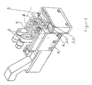
- the horizontal drilling machine shown in FIG. 1 consists of a substructure 1 with two double-spindle machining units 2 which can be moved simultaneously along a travel axis Y and a linear slide unit 3 with a double clamping device 4 for two workpieces which can be moved along a travel axis X.
- the traversing axes X and Y run approximately orthogonally to one another.
- the double clamping device 4 is first loaded with a first workpiece (5.1). After moving the machining units 2 along the travel axis Y towards the workpiece, the first bore (No. 1) is now made in the first workpiece (5.1). If this bore (No. 1) is completed, the first workpiece (5.1) is moved by the linear slide unit 3 along the travel axis X by an amount that is equal to the center distance of the bores of a workpiece. Subsequently, the double clamping device 4 is loaded with the second workpiece (5, 2). As a result of the subsequent feed movement of the processing unit 2, the second bore in the first workpiece and the first bore in the second workpiece are produced simultaneously.
- the first workpiece (5.1) can now be removed and a new workpiece blank (5.3) inserted in the double clamping device 4.
- the first bore is then made in the third workpiece together with the second bore in the second workpiece. If both holes in the second workpiece (5.2) are completed, this workpiece is also removed from the double clamping device 4 and another workpiece is loaded.
- the double clamping device 4 is accordingly moved after each work step by an amount along the travel axis X, which is equal to the center distance of the holes in the workpieces.
- the inventive method creates a continuous loading and Removal process from one workpiece at a time, although two workpieces at the same time to be edited. With high flexibility and high output of the machine thus simpler peripheral devices for loading and unloading the Workpieces can be used.
Landscapes
- Engineering & Computer Science (AREA)
- Mechanical Engineering (AREA)
- Drilling And Boring (AREA)
- Electrical Discharge Machining, Electrochemical Machining, And Combined Machining (AREA)
- Production Of Multi-Layered Print Wiring Board (AREA)
Description
Es zeigt:
Die in der Figur 1 dargestellte Horizontal-Bohrmaschine besteht aus einem Unterbau 1 mit zwei doppelspindeligen Bearbeitungseinheiten 2, die gleichzeitig entlang einer Verfahrachse Y bewegbar sind und einer Linearschlitteneinheit 3 mit einer Doppelspannvorrichtung 4 für zwei Werkstücke, die entlang einer Verfahrachse X bewegbar ist. Bei der dargestellten Ausführung verlaufen die Verfahrachsen X und Y annähernd orthogonal zueinander.
Ist diese Bohrung (Nr.1) fertiggestellt, wird das erste Werkstück (5.1) mittels der Linearschlitteneinheit 3 um einen Betrag entlang der Verfahrachse X bewegt, der gleich dem Mittenabstand der Bohrungen eines Werkstückes ist.
Anschließend erfolgt die Beschickung der Doppelspannvorrichtung 4 mit dem zweiten Werkstück (5, 2). Durch die nachfolgende Vorschubbewegung der Bearbeitungseinheit 2 werden die zweite Bohrung im ersten Werkstück und die erste Bohrung im zweiten Werkstück gleichzeitig hergestellt.
Das erste Werkstück (5.1) kann nun entnommen und ein neues Werkstückrohteil (5.3) in die Doppelspannvorrichtung 4 eingesetzt werden. Nach dem Bewegen der Werkstücke zusammen mit der Doppelspannvorrichtung 4 in die Ausgangsposition erfolgt danach das Setzen der ersten Bohrung in dem dritten Werkstück zusammen mit der zweiten Bohrung in dem zweiten Werkstück.
Sind beide Bohrungen im zweiten Werkstück (5.2) fertiggestellt, wird auch dieses Werkstück aus der Doppelspannvorrichtung 4 entnommen und ein weiteres Werkstück beschickt.
Die Doppelspannvorrichtung 4 wird dementsprechend nach jedem Arbeitsgang um einen Betrag entlang der Verfahrachse X bewegt, der gleich dem Mittenabstand der Bohrungen der Werkstücke ist.
- 1
- Unterbau
- 2
- Bearbeitungseinheit
- 3
- Linearschlitteneinheit
- 4
- Doppelspannvorrichtung
- 5.1
- erstes Werkstück
- 5.2
- zweites Werkstück
- X
- Verfahrachse der Linearschlitteneinheit
- Y
- Verfahrachse der Bearbeitungseinheit
Claims (3)
- Verfahren zum Bohren von zumindest zwei Bohrungen mittels einer Vorrichtung, die zumindest eine doppelspindelige Bearbeitungseinheit (2), die entlang einer ersten Verfahrachse (Y) bewegbar ist und eine Linearschlitteneinheit (3) mit einer Doppelspannvorrichtung (4) für zwei Werkstücke (5.1, 5.2) aufweist, wobei die Linearschlitteneinheit unabhängig von der Bearbeitungseinheit entlang einer zweiten Verfahrachse (X) bewegbar ist,
gekennzeichnet durch folgende Schritte:Einbringung einer ersten Bohrung in ein erstes Werkstück (5.1) (erster Takt),anschließende Einbringung einer zweiten Bohrung in das erste Werkstück (5.1) und gleichzeitig einer ersten Bohrung in ein zweites Werkstück (5.2) (zweiter Takt),Entnahme des ersten Werkstückes (5.1),Beschickung mit einem dritten Werkstück (5.3),Einbringung einer zweiten Bohrung in das zweite Werkstück (5.2) und gleichzeitig einer ersten Bohrung in das dritte Werkstück (5.3). - Verfahren nach Anspruch 1
dadurch gekennzeichnet, daß
nach jedem dem zweiten Takt folgenden Takt ein fertigbearbeitetes Werkstück entnommen und die Doppelspannvorrichtung (4) mit einem weiteren Werkstück beschickt wird. - Verfahren nach einem der Ansprüche 1 oder 2,
dadurch gekennzeichnet, daß
der Abstand zwischen den Bohrungen im Werkstück durch den Betrag des Verfahrweges der Doppelspannvorrichtung (4) bestimmt ist.
Applications Claiming Priority (3)
| Application Number | Priority Date | Filing Date | Title |
|---|---|---|---|
| DE19831625A DE19831625A1 (de) | 1998-07-15 | 1998-07-15 | Verfahren zum Bohren von zumindest zwei Bohrungen im Zwei-Schritt-Takt |
| DE19831625 | 1998-07-15 | ||
| PCT/DE1999/002102 WO2000003824A2 (de) | 1998-07-15 | 1999-07-08 | Verfahren zum bohren von zumindest zwei bohrungen im zwei-schritt-takt |
Publications (2)
| Publication Number | Publication Date |
|---|---|
| EP1017524A1 EP1017524A1 (de) | 2000-07-12 |
| EP1017524B1 true EP1017524B1 (de) | 2003-03-12 |
Family
ID=7874058
Family Applications (1)
| Application Number | Title | Priority Date | Filing Date |
|---|---|---|---|
| EP99945939A Expired - Lifetime EP1017524B1 (de) | 1998-07-15 | 1999-07-08 | Verfahren zum bohren von zumindest zwei bohrungen im zwei-schritt-takt |
Country Status (7)
| Country | Link |
|---|---|
| US (1) | US6345938B1 (de) |
| EP (1) | EP1017524B1 (de) |
| JP (1) | JP3537765B2 (de) |
| AT (1) | ATE234171T1 (de) |
| DE (2) | DE19831625A1 (de) |
| ES (1) | ES2192076T3 (de) |
| WO (1) | WO2000003824A2 (de) |
Cited By (1)
| Publication number | Priority date | Publication date | Assignee | Title |
|---|---|---|---|---|
| CN107225423A (zh) * | 2017-08-09 | 2017-10-03 | 安徽机电职业技术学院 | 一种双工位夹持固定式机械加工夹具 |
Families Citing this family (9)
| Publication number | Priority date | Publication date | Assignee | Title |
|---|---|---|---|---|
| US7727153B2 (en) * | 2003-04-07 | 2010-06-01 | Sonosite, Inc. | Ultrasonic blood vessel measurement apparatus and method |
| US7713210B2 (en) * | 2004-11-23 | 2010-05-11 | St. Jude Medical, Atrial Fibrillation Division, Inc. | Method and apparatus for localizing an ultrasound catheter |
| US20070166096A1 (en) * | 2005-06-03 | 2007-07-19 | Lim Chong K | Joint assembly |
| US9108281B2 (en) * | 2011-03-08 | 2015-08-18 | GM Global Technology Operations LLC | Multi-spindle fastening system |
| CN103008714A (zh) * | 2012-12-19 | 2013-04-03 | 南通第五机床有限公司 | 一种多轴双侧加工的钻床装置 |
| CN107952976B (zh) * | 2017-12-28 | 2019-06-07 | 山东达睿智能设备股份有限公司 | 一种双轴卧式气缸镗孔机 |
| CN108262499B (zh) * | 2017-12-28 | 2019-05-14 | 何莹莹 | 双头自动打孔机 |
| CN110935903A (zh) * | 2019-12-04 | 2020-03-31 | 海盐双赢管件制造有限公司 | 一种自动双钻头钻孔机 |
| CN112917097A (zh) * | 2021-01-13 | 2021-06-08 | 秦宇 | 一种高强度耐腐蚀铝合金的制备方法 |
Family Cites Families (10)
| Publication number | Priority date | Publication date | Assignee | Title |
|---|---|---|---|---|
| DE145367C (de) * | ||||
| US1755401A (en) * | 1928-06-23 | 1930-04-22 | John W Koehl | Automatic boring machine |
| DE1027959B (de) * | 1953-06-30 | 1958-04-10 | Karl Emil Witzig Dipl Ing | Rundschalttisch fuer mehrere Arbeitsstationen |
| US2864416A (en) * | 1956-01-16 | 1958-12-16 | Kaywood Corp | Multiple drilling or like machine |
| US3240084A (en) * | 1960-03-24 | 1966-03-15 | Bendix Corp | Apparatus for boring metal plates |
| US3280659A (en) * | 1965-04-20 | 1966-10-25 | Dillis V Allen | Machine tool |
| US4185943A (en) * | 1978-04-24 | 1980-01-29 | Ameco Corporation | Drilling and tapping machining apparatus |
| JPS6034204A (ja) | 1983-07-29 | 1985-02-21 | Nakamuratome Seimitsu Kogyo Kk | 工作機械 |
| DE4112706C2 (de) * | 1990-04-20 | 1994-02-17 | Hitachi Seiko Kk | Werkzeugwechselvorrichtung |
| DE4031284C2 (de) * | 1990-10-04 | 1993-10-07 | Kopp Kadia Maschinenbau | Vorrichtung zum taktweisen Bearbeiten von Werkstücken |
-
1998
- 1998-07-15 DE DE19831625A patent/DE19831625A1/de not_active Withdrawn
-
1999
- 1999-07-08 WO PCT/DE1999/002102 patent/WO2000003824A2/de not_active Ceased
- 1999-07-08 JP JP2000559954A patent/JP3537765B2/ja not_active Expired - Fee Related
- 1999-07-08 AT AT99945939T patent/ATE234171T1/de not_active IP Right Cessation
- 1999-07-08 DE DE59904526T patent/DE59904526D1/de not_active Expired - Fee Related
- 1999-07-08 EP EP99945939A patent/EP1017524B1/de not_active Expired - Lifetime
- 1999-07-08 ES ES99945939T patent/ES2192076T3/es not_active Expired - Lifetime
- 1999-07-08 US US09/508,723 patent/US6345938B1/en not_active Expired - Fee Related
Cited By (1)
| Publication number | Priority date | Publication date | Assignee | Title |
|---|---|---|---|---|
| CN107225423A (zh) * | 2017-08-09 | 2017-10-03 | 安徽机电职业技术学院 | 一种双工位夹持固定式机械加工夹具 |
Also Published As
| Publication number | Publication date |
|---|---|
| DE19831625A1 (de) | 2000-01-20 |
| WO2000003824A2 (de) | 2000-01-27 |
| JP2002520177A (ja) | 2002-07-09 |
| US6345938B1 (en) | 2002-02-12 |
| ES2192076T3 (es) | 2003-09-16 |
| ATE234171T1 (de) | 2003-03-15 |
| JP3537765B2 (ja) | 2004-06-14 |
| DE59904526D1 (de) | 2003-04-17 |
| WO2000003824A3 (de) | 2000-06-08 |
| EP1017524A1 (de) | 2000-07-12 |
Similar Documents
| Publication | Publication Date | Title |
|---|---|---|
| EP2221141B1 (de) | Fräsverfahren zur automatischen Bearbeitung eines quaderförmigen Werkstücks und Werkzeugmaschine | |
| DE102015001036B4 (de) | Verzahnungs-oder Profilschleifmaschine und Verfahren zum Betreiben einer solchen | |
| WO2021013678A1 (de) | Tiefbohrmaschine | |
| EP1807243B1 (de) | Verfahren zur bearbeitung von rotationsteilen | |
| CH700113B1 (de) | Werkzeugmaschine zur Bearbeitung von Werkstücken, insbesondere zum Schleifen von Werkstücken. | |
| DE102019210876A1 (de) | Tiefbohrmaschine | |
| EP0967038B1 (de) | Vorrichtung zum spanabhebenden Bearbeiten von Werkstücken | |
| EP1017524A1 (de) | Verfahren zum bohren von zumindest zwei bohrungen im zwei-schritt-takt | |
| EP0260692B1 (de) | Kurzhub-Werkzeugmaschine mit einem an einem Maschinengestell in vertikaler (Z-)Richtung verfahrbar gelagerten Bohr- und Frässpindelstock | |
| CH697397B1 (de) | Verfahren und Vorrichtung zum Schleifen eines Profils eines Werkstücks. | |
| DE102015121392A1 (de) | Werkzeughalter | |
| WO2008040136A1 (de) | Spannverfahren für werkstücke zur fertigung von verdichter- oder turbinenräder | |
| DE3337198A1 (de) | Bearbeitungsmaschine | |
| EP3319747A1 (de) | Positioniervorrichtung für ein zylinderkurbelgehäuse und hilfsvorrichtung sowie verfahren zum bearbeiten eines zylinderkurbelgehäuses | |
| DE102017105404B4 (de) | Verfahren zum Bearbeiten von Werkstücken mit einem Bearbeitungszentrum | |
| DE10206949C1 (de) | Zweispindel-Drehmaschine | |
| DE60007777T2 (de) | Bearbeitungsanlage mit rundschleifstationen | |
| EP1029612B1 (de) | Vertikal- oder Horizontalbearbeitungszentrum und Verfahren zur einseitigen oder mehrseitigen Bearbeitung von Werkstücken auf einem Vertikal- oder Horizontalbearbeitungszentrum | |
| EP1175963B1 (de) | Aussenrundschleifmaschine | |
| DE10354622B4 (de) | Verfahren und Vorrichtung zum Herstellen einer Gewinderolle | |
| DE19547665C1 (de) | Werkzeugmaschine mit zwei an einem Maschinengestell angeordneten Bearbeitungsstationen | |
| EP1761712B1 (de) | Verfahren zur herstellung von konzentrisch ineinander lagerbaren drehteilen | |
| EP4464458A1 (de) | Werkzeugmaschine zur herstellung eines werkstücks mit einer aussenkontur und verfahren hierzu | |
| DD212447A1 (de) | Verfahren zur bearbeitung von waelzlagerringen auf mehrspindeldrehautomaten | |
| WO2002086636A2 (de) | Maschinensteuerungsprogrammsystem und verfahren zur steuerung einer werkzeugmaschine |
Legal Events
| Date | Code | Title | Description |
|---|---|---|---|
| PUAI | Public reference made under article 153(3) epc to a published international application that has entered the european phase |
Free format text: ORIGINAL CODE: 0009012 |
|
| 17P | Request for examination filed |
Effective date: 20000301 |
|
| AK | Designated contracting states |
Kind code of ref document: A1 Designated state(s): AT CH DE ES FR GB IT LI |
|
| RAP1 | Party data changed (applicant data changed or rights of an application transferred) |
Owner name: ZF LEMFOERDER METALLWAREN AG |
|
| GRAH | Despatch of communication of intention to grant a patent |
Free format text: ORIGINAL CODE: EPIDOS IGRA |
|
| GRAH | Despatch of communication of intention to grant a patent |
Free format text: ORIGINAL CODE: EPIDOS IGRA |
|
| GRAA | (expected) grant |
Free format text: ORIGINAL CODE: 0009210 |
|
| AK | Designated contracting states |
Designated state(s): AT BE CH CY DE DK ES FI FR GB GR IE IT LI LU MC NL PT SE |
|
| PG25 | Lapsed in a contracting state [announced via postgrant information from national office to epo] |
Ref country code: NL Free format text: LAPSE BECAUSE OF FAILURE TO SUBMIT A TRANSLATION OF THE DESCRIPTION OR TO PAY THE FEE WITHIN THE PRESCRIBED TIME-LIMIT Effective date: 20030312 Ref country code: IE Free format text: LAPSE BECAUSE OF FAILURE TO SUBMIT A TRANSLATION OF THE DESCRIPTION OR TO PAY THE FEE WITHIN THE PRESCRIBED TIME-LIMIT Effective date: 20030312 Ref country code: GR Free format text: LAPSE BECAUSE OF FAILURE TO SUBMIT A TRANSLATION OF THE DESCRIPTION OR TO PAY THE FEE WITHIN THE PRESCRIBED TIME-LIMIT Effective date: 20030312 Ref country code: FI Free format text: LAPSE BECAUSE OF FAILURE TO SUBMIT A TRANSLATION OF THE DESCRIPTION OR TO PAY THE FEE WITHIN THE PRESCRIBED TIME-LIMIT Effective date: 20030312 |
|
| REG | Reference to a national code |
Ref country code: GB Ref legal event code: FG4D Free format text: NOT ENGLISH |
|
| REG | Reference to a national code |
Ref country code: CH Ref legal event code: EP |
|
| GRAH | Despatch of communication of intention to grant a patent |
Free format text: ORIGINAL CODE: EPIDOS IGRA |
|
| GBT | Gb: translation of ep patent filed (gb section 77(6)(a)/1977) |
Effective date: 20030315 |
|
| REG | Reference to a national code |
Ref country code: IE Ref legal event code: FG4D Free format text: GERMAN |
|
| REF | Corresponds to: |
Ref document number: 59904526 Country of ref document: DE Date of ref document: 20030417 Kind code of ref document: P |
|
| REG | Reference to a national code |
Ref country code: CH Ref legal event code: NV Representative=s name: KATZAROV S.A. |
|
| PG25 | Lapsed in a contracting state [announced via postgrant information from national office to epo] |
Ref country code: SE Free format text: LAPSE BECAUSE OF FAILURE TO SUBMIT A TRANSLATION OF THE DESCRIPTION OR TO PAY THE FEE WITHIN THE PRESCRIBED TIME-LIMIT Effective date: 20030612 Ref country code: DK Free format text: LAPSE BECAUSE OF FAILURE TO SUBMIT A TRANSLATION OF THE DESCRIPTION OR TO PAY THE FEE WITHIN THE PRESCRIBED TIME-LIMIT Effective date: 20030612 |
|
| PG25 | Lapsed in a contracting state [announced via postgrant information from national office to epo] |
Ref country code: PT Free format text: LAPSE BECAUSE OF FAILURE TO SUBMIT A TRANSLATION OF THE DESCRIPTION OR TO PAY THE FEE WITHIN THE PRESCRIBED TIME-LIMIT Effective date: 20030620 |
|
| PG25 | Lapsed in a contracting state [announced via postgrant information from national office to epo] |
Ref country code: LU Free format text: LAPSE BECAUSE OF NON-PAYMENT OF DUE FEES Effective date: 20030708 Ref country code: CY Free format text: LAPSE BECAUSE OF FAILURE TO SUBMIT A TRANSLATION OF THE DESCRIPTION OR TO PAY THE FEE WITHIN THE PRESCRIBED TIME-LIMIT Effective date: 20030708 |
|
| PG25 | Lapsed in a contracting state [announced via postgrant information from national office to epo] |
Ref country code: MC Free format text: LAPSE BECAUSE OF NON-PAYMENT OF DUE FEES Effective date: 20030731 Ref country code: BE Free format text: LAPSE BECAUSE OF NON-PAYMENT OF DUE FEES Effective date: 20030731 |
|
| NLV1 | Nl: lapsed or annulled due to failure to fulfill the requirements of art. 29p and 29m of the patents act | ||
| REG | Reference to a national code |
Ref country code: ES Ref legal event code: FG2A Ref document number: 2192076 Country of ref document: ES Kind code of ref document: T3 |
|
| ET | Fr: translation filed | ||
| REG | Reference to a national code |
Ref country code: IE Ref legal event code: FD4D Ref document number: 1017524E Country of ref document: IE |
|
| PLBE | No opposition filed within time limit |
Free format text: ORIGINAL CODE: 0009261 |
|
| STAA | Information on the status of an ep patent application or granted ep patent |
Free format text: STATUS: NO OPPOSITION FILED WITHIN TIME LIMIT |
|
| BERE | Be: lapsed |
Owner name: *ZF LEMFORDER METALLWAREN A.G. Effective date: 20030731 |
|
| 26N | No opposition filed |
Effective date: 20031215 |
|
| PGFP | Annual fee paid to national office [announced via postgrant information from national office to epo] |
Ref country code: CH Payment date: 20070627 Year of fee payment: 9 |
|
| PGFP | Annual fee paid to national office [announced via postgrant information from national office to epo] |
Ref country code: DE Payment date: 20070705 Year of fee payment: 9 |
|
| PGFP | Annual fee paid to national office [announced via postgrant information from national office to epo] |
Ref country code: ES Payment date: 20070824 Year of fee payment: 9 |
|
| PGFP | Annual fee paid to national office [announced via postgrant information from national office to epo] |
Ref country code: AT Payment date: 20070711 Year of fee payment: 9 |
|
| PGFP | Annual fee paid to national office [announced via postgrant information from national office to epo] |
Ref country code: GB Payment date: 20070704 Year of fee payment: 9 |
|
| PGFP | Annual fee paid to national office [announced via postgrant information from national office to epo] |
Ref country code: IT Payment date: 20070730 Year of fee payment: 9 |
|
| PGFP | Annual fee paid to national office [announced via postgrant information from national office to epo] |
Ref country code: FR Payment date: 20070710 Year of fee payment: 9 |
|
| REG | Reference to a national code |
Ref country code: CH Ref legal event code: PL |
|
| GBPC | Gb: european patent ceased through non-payment of renewal fee |
Effective date: 20080708 |
|
| PG25 | Lapsed in a contracting state [announced via postgrant information from national office to epo] |
Ref country code: DE Free format text: LAPSE BECAUSE OF NON-PAYMENT OF DUE FEES Effective date: 20090203 Ref country code: AT Free format text: LAPSE BECAUSE OF NON-PAYMENT OF DUE FEES Effective date: 20080708 |
|
| REG | Reference to a national code |
Ref country code: FR Ref legal event code: ST Effective date: 20090331 |
|
| PG25 | Lapsed in a contracting state [announced via postgrant information from national office to epo] |
Ref country code: LI Free format text: LAPSE BECAUSE OF NON-PAYMENT OF DUE FEES Effective date: 20080731 Ref country code: GB Free format text: LAPSE BECAUSE OF NON-PAYMENT OF DUE FEES Effective date: 20080708 Ref country code: CH Free format text: LAPSE BECAUSE OF NON-PAYMENT OF DUE FEES Effective date: 20080731 |
|
| PG25 | Lapsed in a contracting state [announced via postgrant information from national office to epo] |
Ref country code: IT Free format text: LAPSE BECAUSE OF NON-PAYMENT OF DUE FEES Effective date: 20080708 Ref country code: FR Free format text: LAPSE BECAUSE OF NON-PAYMENT OF DUE FEES Effective date: 20080731 |
|
| REG | Reference to a national code |
Ref country code: ES Ref legal event code: FD2A Effective date: 20080709 |
|
| PG25 | Lapsed in a contracting state [announced via postgrant information from national office to epo] |
Ref country code: ES Free format text: LAPSE BECAUSE OF NON-PAYMENT OF DUE FEES Effective date: 20080709 |