EP1017077A1 - Schalteranordnung - Google Patents
Schalteranordnung Download PDFInfo
- Publication number
- EP1017077A1 EP1017077A1 EP99125564A EP99125564A EP1017077A1 EP 1017077 A1 EP1017077 A1 EP 1017077A1 EP 99125564 A EP99125564 A EP 99125564A EP 99125564 A EP99125564 A EP 99125564A EP 1017077 A1 EP1017077 A1 EP 1017077A1
- Authority
- EP
- European Patent Office
- Prior art keywords
- operation member
- angle adjusting
- rotary operation
- push
- light
- Prior art date
- Legal status (The legal status is an assumption and is not a legal conclusion. Google has not performed a legal analysis and makes no representation as to the accuracy of the status listed.)
- Granted
Links
Images

Classifications
-
- H—ELECTRICITY
- H01—ELECTRIC ELEMENTS
- H01H—ELECTRIC SWITCHES; RELAYS; SELECTORS; EMERGENCY PROTECTIVE DEVICES
- H01H25/00—Switches with compound movement of handle or other operating part
- H01H25/06—Operating part movable both angularly and rectilinearly, the rectilinear movement being along the axis of angular movement
- H01H25/065—Operating part movable both angularly and rectilinearly, the rectilinear movement being along the axis of angular movement using separate operating parts, e.g. a push button surrounded by a rotating knob
-
- H—ELECTRICITY
- H01—ELECTRIC ELEMENTS
- H01H—ELECTRIC SWITCHES; RELAYS; SELECTORS; EMERGENCY PROTECTIVE DEVICES
- H01H9/00—Details of switching devices, not covered by groups H01H1/00 - H01H7/00
- H01H9/18—Distinguishing marks on switches, e.g. for indicating switch location in the dark; Adaptation of switches to receive distinguishing marks
- H01H9/182—Illumination of the symbols or distinguishing marks
Definitions
- This invention relates to a switch assembly which includes a push operation member and a rotary operation member.
- the push operation member is assembled to an exclusive holder so that a pushing operation is possible, and a first switch element is actuated by this pushing operation.
- a light emitting element and a light guiding member are provided for the push operation member and a light emitted by the light emitting element is adapted to be guided by the light guiding member to pass the light through a light permeable part incorporated in the push operation member.
- the rotary operation member is provided around an outer periphery of the holder for the push operation member so that a rotary operation is possible, and a second switch element is actuated by this rotary operation.
- Either one of the rotary operation member and the push operation member is formed with angle adjusting notches, while the other is provided with an angle adjusting ball together with a helical compression spring.
- the angle adjusting ball is adapted to engage with the adjusting notches by means of a spring force of the helical compression spring to give an angular adjustment to the rotary operation of the rotary operation member.
- the light guiding member, the holder for the push operation member, the angle adjusting ball, the helical compression spring, and the angle adjusting notches have been so constructed as mounted one on another in an axial direction, thus making the whole rotary operation member thickened in the axial direction.
- the invention has been made in view of the above circumstances, and therefore, it is an object of the invention to provide a switch assembly in which the number of components to be employed has been decreased and a thinner shape of the whole structure can be attained.
- a switch assembly in that it comprises a light emitting element, a light guiding member for guiding a light emitted from the light emitting element, a push operation member including a light permeable part for passing through the light guided by the light guiding member, the push operation member being assembled to the light guiding member in a manner operable by a pushing operation, first switch elements adapted to be actuated by the pushing operation of the push operation member, a rotary operation member provided around an outer periphery of the light guiding member in a manner operable by a rotary operation, second switch elements adapted to be actuated by the rotary operation of the rotary operation member, angle adjusting notches provided in one of an outer periphery of the light guiding member and an inner periphery of the rotary operation member, and an angle adjusting piece integrally formed in the other of the outer periphery of the light guiding member and the inner periphery of the rotary operation member so as to dia
- the push operation member is mounted on the light guiding member and do not require a holder exclusively for assembling the push operation member.
- the angle adjusting piece is integrally formed at the other of the outer periphery of the light guiding member and the inner periphery of the rotary operating member, and therefore it is not required as a separate component.
- the switch assembly can be made thinner in an axial direction than the conventional assembly, because the angle adjusting piece and the angle adjusting notches face with each other in a diametrical direction of the rotary operation member between the rotary operation member and the light guiding member.
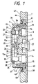
- Fig. 1 shows the switch assembly for air conditioning installed on an instrument panel of the vehicle, particularly an automobile in a vertical section
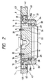
- Fig. 2 shows the switch assembly in a cross section
- Fig. 3 shows the switch assembly in an exploded state.
- a light emitting element LED 2 is mounted on a circuit board 1 which also serves as a mounting base.
- Tact switches 3, 4 are mounted at both upper and lower parts of the LED 2.
- the tact switches 3, 4 are adapted to be turned on by pushing their operable portions 3a, 4a in a square pillar form.
- the tact switches 3, 4 have restoring means such as return springs or the like (not shown) for normally retaining the operable parts 3a, 4a at their off positions before they are pushed in.
- An upper one 3 of the tact switches incorporates an LED 5 so as to be positioned behind the operable portion 3a.
- the circuit board 1 is provided with fitting holes 6, 6 at both sides of the LED 2, as shown in Figs. 2 and 3. Moreover, at an area around the fitting holes 6, 6 and the tact switches 3, 4 is provided a fixed common contact piece 7 in an annular shape which has a plurality of, seven, for example, fixed selection contact pieces 8, 8 .... equidistantly provided at its outer periphery.
- a light guiding member 9 which is made of a synthetic resin having a light permeability such as acrylic resin is fitted to the circuit board 1.
- This light guiding member 9 has an outer shape of a thick disc and a recess 10 for containing the LED formed at a rear face of its central part (adjacent to the circuit board 1 in the drawings). Threaded bores 11, 11 are formed in the light guiding member 9 at both sides of the recess 10 spaced apart with the same distance therebetween as the fitting holes 6, 6 in the circuit board 1.
- the light guiding member 9 are formed at a front face of its central part (remote from the circuit board 1 in the drawings) with a light releasing recess 12 which has a diagonally upwardly oriented face 12a and another light releasing recess 13 which has a diagonally downwardly oriented face 13a.
- Tact switch receiving holes 14, 15 are formed in both upper and lower parts of the light releasing recesses 12, 13, and shaft receiving holes 16, 16 are formed at both left and right hands thereof.
- shaft bearing holes 17, 18, 17, 18 respectively In outer walls of the shaft receiving holes 16, 16 are formed shaft bearing holes 17, 18, 17, 18 respectively.
- a number of angle adjusting notches 19, 19... are provided on an outer circumference of the light guiding member 9 at its one edge (adjacent to the circuit board 1 in the drawings) at a pitch equal to the arrangement of the fixed selection contact pieces 8, 8...
- the light guiding member 9 is mounted on the circuit board 1 by bringing the threaded bores 11, 11 in alignment with the fitting holes 6, 6 in the circuit board 1, and then screwing screws 20, 20 from the rear face of the circuit board 1 through the fitting holes 6, 6 into the threaded bores 11, 11 for clamping.
- the LED 2 is contained in the LED receiving recess 10
- the tact switches 3, 4 are contained in the tact switch receiving holes 14, 15.
- the push operation member consists of an upper first push operation member 21 and a lower second push operation member 22 in a semi-circular shape. Respective arcuate outer circumferences of both the push operation members 21, 22 are provided with flange portions 23, 24. Arms 25, 25, 26, 26 are projectingly formed from back faces at both sides of the arcuate portions. The arms 25, 25, 26, 26 have shafts 27, 27, 28, 28 projectingly formed at outer side faces of their distal end portions.
- the push operation members 21, 22 have light permeable parts 29, 30 in a form of letters "A/C” and "MODE".
- the push operation members 21, 22 have a lightproofing property at areas except the light permeable parts 29, 30.
- Two operating portions 31, 31, 32, 32 are respectively projected from the back faces of the push operation members 21, 22 at the middle of the arcuate portions. These operating portions 31, 31, 32, 32 are respectively correspond to the operable parts 3a, 4a of the tact switches 3, 4. In particular, they are spaced apart with the same distance therebetween as the side walls of the operable parts 3a, 4a and their tip ends are rounded so as to push the left and right side walls of the operable parts 3a, 4a.
- a lens containing hole 33 into which a lens 34 is incorporated.
- a light shielding piece 35 which extends remotely from the arcuate portion as shown in Fig. 1.
- the push operation members 21, 22 make their shafts 27, 27, 28, 28 received in the shaft receiving holes 16, 16 in the light guiding member 9 and resiliently inserted into the shaft bearing holes 17, 17, 18, 18 to bring the rounded ends of the operating portions 31, 31, 32, 32 into contact with edge faces of the left and right side walls of the operable parts 3a, 4a of the tact switches 34.
- the shafts 27, 28, 28 are provided with slanted faces 27a, 28a (Refer to Figs. 2 and 3) beforehand.
- the first push operation member 21 is assembled prior to the second push operating member 22, so that the light shielding piece 35 is located extendingly up to the back of the second push operation member 22 thereby to close a gap between the push operating members 21, 22.
- the rotary operation member 36 is in a form of a ring encircling the light guiding member 9 and both the push operation members 21, 22, and made of a synthetic resin.
- a knurled part 37 is formed around an outer periphery of the rotary operation member 36 to improve gripping ability of a user's fingers.
- At one axial end portion (remote from the circuit board 1 in the drawings) of the rotary operation member 36 is provided an inner flange 38 and at the other end portion (adjacent to the circuit board 1 in the drawings) is provided an outer flange 39.
- an angle adjusting piece 40 and a balance piece 41 each of which is integrally formed by molding a synthetic resin are symmetrically provided at an inner periphery of the rotary operation member 36.
- the angle adjusting piece 40 and the balance piece 41 are in a shape of an arc which is slightly larger in diameter than the outer circumference of the light guiding member 9 and swingingly connected to the rotary operation member 36 at their middle portions.
- the angle adjusting piece 40 has, inside the both ends thereof, projections 42 for engaging with each one of the angle adjusting notches 19, 19... at an interval corresponding to a few pitches (for example, two pitches) of the angle adjusting notches 19.
- a movable contact piece 43 and a balance contact piece 44 are symmetrically attached to the back face of the rotary operation member 36 by means of screws 45, 46 respectively.
- the movable contact piece 43 has a movable common contact portion 43a and a movable selection contact portion 43b.
- the movable common contact portion 43a and the balance contact piece 44 correspond to the above mentioned fixed common contact piece 7, while the movable selection contact portion 43b corresponds to the fixed selection contact pieces 8, 8 ....
- the rotary operation member 36 encircles both the push operation members 21, 22 and the light guiding member 9, covering the flange portions (outer flange portions) 23, 24 of the push operation members 21, 22 with the inner flange 38, and bring the movable common contact portion 43a of the movable contact piece 43 and the balance contact piece 44 into contact with the fixed common contact piece 7, thereby to bring the movable selection contact portion 43b into contact with the arranged part of the fixed selection contact pieces 8, 8 .
- a panel 47 is connected to the circuit board 1 by mating the rotary operation member 36 with an opening 48 in the panel 47 while covering the outer flange 39 with a clamping part 49 formed at an inner periphery of the opening 48, thus assembling the whole switch assembly for air conditioning.
- the air conditioning control unit which is not shown actuates a cooling system and causes the LED 5 to emit a light at the same time.
- the light emitted from the LED 5 is released through the lens 34 in front of the first push operation member 21 in order to indicate that the cooling system has started to operate.
- the first push operation member 21 is restored in association with a return of the operable parts 3a of the tact switch 3 by means of a biasing force of retention means such as a return spring or the like.
- the first push operation member 21 When the first push operation member 21 is pushed again in this state, the first push operation member 21 rotates in the same manner as described above to push the operable part 3a of the tact switch 3 again, thereby to turn on the tact switch 3 again. This will cause the control unit to stop the operation of the cooling system, and at the same time, shut off the LED 5 to discontinue the indication of the operation of the cooling system.
- the control unit actuates the cooling system again, and causes the LED 5 to emit the light at the same time, to indicate the operation of the cooling system.
- the second push operation member 22 rotates toward the circuit board 1 around the shafts 28, 28 to push the operable part 4a of the tact switch 4 by means of the operating portions 32, 32 to turn on the tact switch 4. This will cause the control unit to change operation mode (for example, strong or weak) of the cooling system.
- operation mode for example, strong or weak
- the second push operation member 22 is restored in association with a return of the operable part 4a of the tact switch 4 by means of a biasing force of the retention means such as a return spring or the like.
- the second push operation member 22 When the second push operation member 22 is pushed again in this state, the second push operation member 22 rotates in the same manner as described above to push the operable part 4a of the tact switch 4 again, thereby turning on the tact switch 4 again. This will cause the control unit to change the operation mode of the cooling system again.
- the LED 2 In the nighttime, the LED 2 emits a light by operating a light switch of the automobile. The light emitted from the LED 2 is released from the slanted faces 12a, 13a of the light releasing recesses 12, 13 through the light guiding member 9 to light up the light permeable part 29 (the letters "A/C") of the first push operation member 21 and the light permeable part 30 (the letters "MODE”) of the second push operation member 22.
- the light shielding piece 35 effectively serves to prevent the light emitted from the LED 2 from leaking through the gap between the first push operation member 21 and the second push operation member 22.
- the tact switches 3, 4 serve as the first switch elements to be operated by the pushing operation of the first push operation member 21 and the second push operation member 22.
- the movable contact piece 43 and the balance contact piece 44 synchronously rotates.
- the movable common contact portion 43a of the movable contact piece 43 slides along the front face of the fixed common contact piece 7 of the circuit board 1, and the movable selection contact portion 43b slides along the front face of the arranged part of the fixed selection contact pieces 8, 8 .... to successively contact the fixed selection contact pieces 8, 8 .... one by one.
- connections between the fixed common contact piece 7 and the fixed selection contact pieces 8, 8 .... are performed one by one, and accordingly, the control unit performs selection of mode of a ventilator, for example, for blowing out air in the air conditioner in the automobile.
- the angle adjusting piece 40 and the balance piece 41 synchronously rotate.
- the angle adjusting piece 40 sliding along the outer periphery of the light guiding member 9 makes its projections 42 engage with each one of the angle adjusting notches 19, 19 .... provided on the outer circumference of the light guiding member 9 one by one, thereby to impart an angular adjustment to the rotary operation of the rotary operation member 36.
- the balance piece 41 slides around the outer periphery of the light guiding member 9 in symmetry with the angle adjusting piece 40, while the balance contact piece 44 slides along the front face of the fixed common contact piece 7 in symmetry with the movable contact piece 43, to keep a diametrical and an axial balance of the rotary operation member 36.
- the above described movable contact piece 43, the fixed common contact piece 7, and the fixed selection contact pieces 8, 8 ... serve as the second switch elements to be operated by the rotary operation of the rotary operation member 36.
- the push operation member including the first push operation member 21 and the second push operation member 22 is assembled to the light guiding member 9 and does not require such exclusive holder as in the conventional construction in assembling the push operating members 21, 22.
- the angle adjusting piece 40 is integrally formed at the inner periphery of the rotary operation member 36 and need not be a separate component. As the results, the components to be used are decreased in number, thus achieving the low cost of the product.
- the light emitting element which emits the light to be guided by the light guiding member 9 not only the LED but also a lamp, etc. may be used.
- the other LEDs also may be substituted by lamps respectively.
- the angle adjusting notches and the angle adjusting piece may be formed at the inner periphery of the rotary operation member contrarily to the above described structure, and the angle adjusting piece may be integrally formed at the outer periphery of the light guiding member.
- the whole switch assembly can be used not only for the air conditioning of the vehicles but also widely used as a general switch assembly.
- the number of the components to be used is decreased and the whole switch assembly can be made axially down-sized.
Applications Claiming Priority (2)
| Application Number | Priority Date | Filing Date | Title |
|---|---|---|---|
| JP37379798 | 1998-12-28 | ||
| JP10373797A JP2000195362A (ja) | 1998-12-28 | 1998-12-28 | スイッチ装置 |
Publications (2)
| Publication Number | Publication Date |
|---|---|
| EP1017077A1 true EP1017077A1 (de) | 2000-07-05 |
| EP1017077B1 EP1017077B1 (de) | 2003-05-21 |
Family
ID=18502775
Family Applications (1)
| Application Number | Title | Priority Date | Filing Date |
|---|---|---|---|
| EP19990125564 Expired - Lifetime EP1017077B1 (de) | 1998-12-28 | 1999-12-21 | Schalteranordnung |
Country Status (3)
| Country | Link |
|---|---|
| EP (1) | EP1017077B1 (de) |
| JP (1) | JP2000195362A (de) |
| DE (1) | DE69908076T2 (de) |
Cited By (12)
| Publication number | Priority date | Publication date | Assignee | Title |
|---|---|---|---|---|
| DE10016180A1 (de) * | 2000-03-31 | 2001-10-11 | Audi Ag | Multifunktionsbedienelement |
| DE10059793A1 (de) * | 2000-12-01 | 2002-06-13 | Volkswagen Ag | Multifunktions-Bedieneinrichtung für ein Kraftfahrzeug |
| WO2002099825A1 (fr) * | 2001-06-07 | 2002-12-12 | Valeo Electronique | Dispositif de commande pour vehicule automobile destine notamment a piloter un ordinateur de bord |
| FR2830676A1 (fr) * | 2001-10-05 | 2003-04-11 | Valeo Climatisation | Tableau de commande modulaire |
| EP1865526A1 (de) * | 2006-06-06 | 2007-12-12 | Whirlpool Corporation | Programmwahlschalter für Haushaltsgeräte |
| EP1995753A1 (de) | 2007-05-25 | 2008-11-26 | Electrolux Home Products Corporation N.V. | Schaltelement für ein Gerät, insbesondere für ein Haushaltsgerät |
| CN100459006C (zh) * | 2005-03-10 | 2009-02-04 | 阿尔卑斯电气株式会社 | 复合输入装置 |
| DE10239387B4 (de) * | 2002-03-01 | 2011-04-07 | Volkswagen Ag | Versenkbarer Schalter |
| CN101667501B (zh) * | 2008-09-05 | 2011-06-22 | 鸿富锦精密工业(深圳)有限公司 | 集成输入单元 |
| DE102011106784A1 (de) | 2011-07-06 | 2013-01-10 | Volkswagen Aktiengesellschaft | Bedieneinheit für eine Funktionseinrichtung und Fahrzeug mit einer solchen Bedieneinheit, insbesondere zum Bedienen einer Klimatisierungsanlage |
| CN109724009A (zh) * | 2017-10-31 | 2019-05-07 | 丰田自动车株式会社 | 车载照明装置 |
| DE102005032508B4 (de) * | 2004-07-15 | 2021-05-20 | BSH Hausgeräte GmbH | Bedienelement mit Leuchtquelle |
Families Citing this family (2)
| Publication number | Priority date | Publication date | Assignee | Title |
|---|---|---|---|---|
| KR100453126B1 (ko) * | 2002-04-29 | 2004-10-15 | 씨멘스브이디오한라 주식회사 | 엘이디 조명 버튼장치 |
| KR100877827B1 (ko) * | 2002-07-29 | 2009-01-12 | 한라공조주식회사 | 복합 스위치 |
Citations (1)
| Publication number | Priority date | Publication date | Assignee | Title |
|---|---|---|---|---|
| EP0605324A1 (de) * | 1992-12-28 | 1994-07-06 | Valeo Thermique Habitacle | Steuertafel für Fahrzeug-Heizung oder -Klimaanlage |
-
1998
- 1998-12-28 JP JP10373797A patent/JP2000195362A/ja active Pending
-
1999
- 1999-12-21 DE DE1999608076 patent/DE69908076T2/de not_active Expired - Fee Related
- 1999-12-21 EP EP19990125564 patent/EP1017077B1/de not_active Expired - Lifetime
Patent Citations (1)
| Publication number | Priority date | Publication date | Assignee | Title |
|---|---|---|---|---|
| EP0605324A1 (de) * | 1992-12-28 | 1994-07-06 | Valeo Thermique Habitacle | Steuertafel für Fahrzeug-Heizung oder -Klimaanlage |
Cited By (17)
| Publication number | Priority date | Publication date | Assignee | Title |
|---|---|---|---|---|
| DE10016180C2 (de) * | 2000-03-31 | 2002-01-31 | Audi Ag | Multifunktionsbedienelement |
| DE10016180A1 (de) * | 2000-03-31 | 2001-10-11 | Audi Ag | Multifunktionsbedienelement |
| DE10059793B4 (de) * | 2000-12-01 | 2014-03-27 | Volkswagen Ag | Multifunktions-Bedieneinrichtung für ein Kraftfahrzeug |
| DE10059793A1 (de) * | 2000-12-01 | 2002-06-13 | Volkswagen Ag | Multifunktions-Bedieneinrichtung für ein Kraftfahrzeug |
| WO2002099825A1 (fr) * | 2001-06-07 | 2002-12-12 | Valeo Electronique | Dispositif de commande pour vehicule automobile destine notamment a piloter un ordinateur de bord |
| FR2825833A1 (fr) * | 2001-06-07 | 2002-12-13 | Valeo Electronique | Dispositf de commande pour vehicule automobile destine notamment a piloter un ordinateur de bord |
| US6878886B1 (en) | 2001-06-07 | 2005-04-12 | Valco Electronique | Control device for motor vehicle in particular for controlling an on-board computer |
| FR2830676A1 (fr) * | 2001-10-05 | 2003-04-11 | Valeo Climatisation | Tableau de commande modulaire |
| WO2003043041A1 (fr) * | 2001-10-05 | 2003-05-22 | Valeo Climatisation | Tableau de commande modulaire |
| DE10239387B4 (de) * | 2002-03-01 | 2011-04-07 | Volkswagen Ag | Versenkbarer Schalter |
| DE102005032508B4 (de) * | 2004-07-15 | 2021-05-20 | BSH Hausgeräte GmbH | Bedienelement mit Leuchtquelle |
| CN100459006C (zh) * | 2005-03-10 | 2009-02-04 | 阿尔卑斯电气株式会社 | 复合输入装置 |
| EP1865526A1 (de) * | 2006-06-06 | 2007-12-12 | Whirlpool Corporation | Programmwahlschalter für Haushaltsgeräte |
| EP1995753A1 (de) | 2007-05-25 | 2008-11-26 | Electrolux Home Products Corporation N.V. | Schaltelement für ein Gerät, insbesondere für ein Haushaltsgerät |
| CN101667501B (zh) * | 2008-09-05 | 2011-06-22 | 鸿富锦精密工业(深圳)有限公司 | 集成输入单元 |
| DE102011106784A1 (de) | 2011-07-06 | 2013-01-10 | Volkswagen Aktiengesellschaft | Bedieneinheit für eine Funktionseinrichtung und Fahrzeug mit einer solchen Bedieneinheit, insbesondere zum Bedienen einer Klimatisierungsanlage |
| CN109724009A (zh) * | 2017-10-31 | 2019-05-07 | 丰田自动车株式会社 | 车载照明装置 |
Also Published As
| Publication number | Publication date |
|---|---|
| DE69908076T2 (de) | 2003-11-20 |
| JP2000195362A (ja) | 2000-07-14 |
| EP1017077B1 (de) | 2003-05-21 |
| DE69908076D1 (de) | 2003-06-26 |
Similar Documents
| Publication | Publication Date | Title |
|---|---|---|
| EP1017077B1 (de) | Schalteranordnung | |
| US7381128B2 (en) | Operating device of air conditioner for vehicle | |
| US7342186B2 (en) | Knob force transfer module | |
| EP1518728B1 (de) | Betätigungsvorrichtung einer Kraftfahrzeugklimaanlage | |
| US5180050A (en) | Pushbutton rotary switch | |
| US7811160B2 (en) | Operating device of vehicle air conditioner | |
| EP1708217B1 (de) | Schaltmechanismus | |
| JP2006278342A (ja) | 回転型ライトスイッチ | |
| US8967021B2 (en) | Operating device | |
| JP5635936B2 (ja) | 操作装置 | |
| JP4263572B2 (ja) | 車両用空調装置の操作装置 | |
| JP6126704B2 (ja) | 可動部付電子部品 | |
| JPH10294031A (ja) | 操作装置 | |
| JP2002287840A (ja) | 操作装置 | |
| JP2004103376A (ja) | スイッチ装置 | |
| JP2002197946A (ja) | 多方向スイッチ | |
| JP2553214Y2 (ja) | 操作ノブのアクション構造 | |
| JP2016185743A (ja) | 車両空調用操作装置 | |
| JP2001256864A (ja) | 操作スイッチ装置 | |
| KR20060026647A (ko) | 로타리 스위치 | |
| JPH0711728U (ja) | 発光装置付スイッチ |
Legal Events
| Date | Code | Title | Description |
|---|---|---|---|
| PUAI | Public reference made under article 153(3) epc to a published international application that has entered the european phase |
Free format text: ORIGINAL CODE: 0009012 |
|
| AK | Designated contracting states |
Kind code of ref document: A1 Designated state(s): DE FR GB |
|
| AX | Request for extension of the european patent |
Free format text: AL;LT;LV;MK;RO;SI |
|
| 17P | Request for examination filed |
Effective date: 20000607 |
|
| AKX | Designation fees paid |
Free format text: DE FR GB |
|
| GRAH | Despatch of communication of intention to grant a patent |
Free format text: ORIGINAL CODE: EPIDOS IGRA |
|
| GRAH | Despatch of communication of intention to grant a patent |
Free format text: ORIGINAL CODE: EPIDOS IGRA |
|
| GRAA | (expected) grant |
Free format text: ORIGINAL CODE: 0009210 |
|
| AK | Designated contracting states |
Designated state(s): DE FR GB |
|
| REG | Reference to a national code |
Ref country code: GB Ref legal event code: FG4D |
|
| REF | Corresponds to: |
Ref document number: 69908076 Country of ref document: DE Date of ref document: 20030626 Kind code of ref document: P |
|
| ET | Fr: translation filed | ||
| PLBE | No opposition filed within time limit |
Free format text: ORIGINAL CODE: 0009261 |
|
| STAA | Information on the status of an ep patent application or granted ep patent |
Free format text: STATUS: NO OPPOSITION FILED WITHIN TIME LIMIT |
|
| 26N | No opposition filed |
Effective date: 20040224 |
|
| PG25 | Lapsed in a contracting state [announced via postgrant information from national office to epo] |
Ref country code: DE Free format text: LAPSE BECAUSE OF NON-PAYMENT OF DUE FEES Effective date: 20040701 |
|
| PGFP | Annual fee paid to national office [announced via postgrant information from national office to epo] |
Ref country code: FR Payment date: 20041208 Year of fee payment: 6 |
|
| PGFP | Annual fee paid to national office [announced via postgrant information from national office to epo] |
Ref country code: GB Payment date: 20041215 Year of fee payment: 6 |
|
| PG25 | Lapsed in a contracting state [announced via postgrant information from national office to epo] |
Ref country code: GB Free format text: LAPSE BECAUSE OF NON-PAYMENT OF DUE FEES Effective date: 20051221 |
|
| GBPC | Gb: european patent ceased through non-payment of renewal fee |
Effective date: 20051221 |
|
| PG25 | Lapsed in a contracting state [announced via postgrant information from national office to epo] |
Ref country code: FR Free format text: LAPSE BECAUSE OF NON-PAYMENT OF DUE FEES Effective date: 20060831 |
|
| REG | Reference to a national code |
Ref country code: FR Ref legal event code: ST Effective date: 20060831 |