EP1016805A2 - Dispositifs à fluide magnétorhéologique - Google Patents
Dispositifs à fluide magnétorhéologique Download PDFInfo
- Publication number
- EP1016805A2 EP1016805A2 EP00105842A EP00105842A EP1016805A2 EP 1016805 A2 EP1016805 A2 EP 1016805A2 EP 00105842 A EP00105842 A EP 00105842A EP 00105842 A EP00105842 A EP 00105842A EP 1016805 A2 EP1016805 A2 EP 1016805A2
- Authority
- EP
- European Patent Office
- Prior art keywords
- fluid
- piston
- damper
- coil
- housing
- Prior art date
- Legal status (The legal status is an assumption and is not a legal conclusion. Google has not performed a legal analysis and makes no representation as to the accuracy of the status listed.)
- Granted
Links
Images


Classifications
-
- H—ELECTRICITY
- H01—ELECTRIC ELEMENTS
- H01F—MAGNETS; INDUCTANCES; TRANSFORMERS; SELECTION OF MATERIALS FOR THEIR MAGNETIC PROPERTIES
- H01F1/00—Magnets or magnetic bodies characterised by the magnetic materials therefor; Selection of materials for their magnetic properties
- H01F1/44—Magnets or magnetic bodies characterised by the magnetic materials therefor; Selection of materials for their magnetic properties of magnetic liquids, e.g. ferrofluids
- H01F1/447—Magnets or magnetic bodies characterised by the magnetic materials therefor; Selection of materials for their magnetic properties of magnetic liquids, e.g. ferrofluids characterised by magnetoviscosity, e.g. magnetorheological, magnetothixotropic, magnetodilatant liquids
-
- F—MECHANICAL ENGINEERING; LIGHTING; HEATING; WEAPONS; BLASTING
- F16—ENGINEERING ELEMENTS AND UNITS; GENERAL MEASURES FOR PRODUCING AND MAINTAINING EFFECTIVE FUNCTIONING OF MACHINES OR INSTALLATIONS; THERMAL INSULATION IN GENERAL
- F16F—SPRINGS; SHOCK-ABSORBERS; MEANS FOR DAMPING VIBRATION
- F16F13/00—Units comprising springs of the non-fluid type as well as vibration-dampers, shock-absorbers, or fluid springs
- F16F13/04—Units comprising springs of the non-fluid type as well as vibration-dampers, shock-absorbers, or fluid springs comprising both a plastics spring and a damper, e.g. a friction damper
- F16F13/26—Units comprising springs of the non-fluid type as well as vibration-dampers, shock-absorbers, or fluid springs comprising both a plastics spring and a damper, e.g. a friction damper characterised by adjusting or regulating devices responsive to exterior conditions
- F16F13/30—Units comprising springs of the non-fluid type as well as vibration-dampers, shock-absorbers, or fluid springs comprising both a plastics spring and a damper, e.g. a friction damper characterised by adjusting or regulating devices responsive to exterior conditions comprising means for varying fluid viscosity, e.g. of magnetic or electrorheological fluids
- F16F13/305—Units comprising springs of the non-fluid type as well as vibration-dampers, shock-absorbers, or fluid springs comprising both a plastics spring and a damper, e.g. a friction damper characterised by adjusting or regulating devices responsive to exterior conditions comprising means for varying fluid viscosity, e.g. of magnetic or electrorheological fluids magnetorheological
-
- F—MECHANICAL ENGINEERING; LIGHTING; HEATING; WEAPONS; BLASTING
- F16—ENGINEERING ELEMENTS AND UNITS; GENERAL MEASURES FOR PRODUCING AND MAINTAINING EFFECTIVE FUNCTIONING OF MACHINES OR INSTALLATIONS; THERMAL INSULATION IN GENERAL
- F16F—SPRINGS; SHOCK-ABSORBERS; MEANS FOR DAMPING VIBRATION
- F16F9/00—Springs, vibration-dampers, shock-absorbers, or similarly-constructed movement-dampers using a fluid or the equivalent as damping medium
- F16F9/32—Details
- F16F9/53—Means for adjusting damping characteristics by varying fluid viscosity, e.g. electromagnetically
- F16F9/535—Magnetorheological [MR] fluid dampers
Definitions
- Incompressible fluids have been used in shock absorbers and other dampers, as well as in elastomeric mounts, for decades.
- the use of a controllable fluid in a damper affords some interesting possibilities relative to providing widely varying damping for varying conditions encountered by the damper. Nonetheless, the use of controllable fluids was generally restricted to the area of clutches, with a few exceptions, until the mid-1980's.
- MR fluids inherently have higher yield strengths and are, therefore, capable of generating greater damping forces. Further, contamination does not pose the performance degradation threat for MR fluids that it does for ER fluids. Still further, MR fluids are activated by magnetic fields which are easily produced by simple, low-voltage electromagnetic coils.
- Enhancements include:
- the apparatus includes a housing for containing a volume of MR fluid; a piston adapted for movement within the housing, the piston being formed of ferrous metal, having a number, N, of windings of conductive wire incorporated therein to define a coil that produces magnetic flux in and around the piston; and having a configuration in which A core A pole , and A path A pole ⁇ B opt B knee where A core is a minimum lateral cross-sectional area of the piston within the coil, A path is a minimum lateral cross-sectional area of magnetically permeable material defining a return path for the magnetic flux, A pole is the surface area of the pistons magnetic pole, B opt is an optimum magnetic flux density for the MR fluid, and B knee is a magnetic flux density at which the ferrous metal begins to saturate.
- the housing may be provided with a sleeve of ferrous material to increase the cross-sectional area of the return flow path for the magnetic flux, A path , for configurations in which the return path for the magnetic flux is through the housing.
- the housing may be a twin-tube design; the magnet may be formed on a spool-shaped piston or wound as a toroid thereon; the magnet could be positioned within the twin-tube housing rather than on the piston; loss of MR fluid can be prevented by topping the damper with a less dense fluid, using a scraper and seal combination, or using a sealless design.
- the piston may be formed from conventional ferrous materials (in either solid or laminate form) or from powdered metals. These features may be embodied in a mount as well as in a damper.
- FIG. 1 A first embodiment of the damper of the present invention is depicted in Fig. 1 generally at 16 .
- Damper 16 is made up of two principal components: housing 20 and piston 30 .
- Housing 20 contains a volume of magnetorheological (MR) fluid 18 .
- MR magnetorheological
- One fluid which has shown itself to be particularly well-suited for this application consists of carbonyl iron particles suspended in silicone oil.
- This MR fluid has a relative magnetic permeability between 3 and 15 at a magnetic flux density of .002 tesla (20 gauss).
- An MR damper has two principal modes of operation: sliding plate and flow (or valve) modes. Components of both modes will be present in every MR damper, with the force component of the flow mode dominating.
- Housing 20 is a generally cylindrical tube with a first closed end 22 with an attachment eye 24 associated therewith.
- a cylindrical sleeve 25 may be affixed to the inner cylinder by any conventional means (e.g., press fit, welding, adhesive) to increase the cross-sectional surface area of housing 20 , as will be discussed in greater detail hereafter.
- a second, or open, end of the cylinder is closed by end member 26 .
- a first seal 27 extends about the outer periphery of member 26 to prevent fluid leakage between housing 20 and member 26 .
- a second annular seal 28 is housed in a groove in the inner periphery of member 26 and seals against shaft 32 .
- a scraper 29 can be used to wipe the MR fluid off the surface of shaft 32 so as to minimize loss of MR fluid past seal 28 .
- the upper regions of housing 20 can be filled with a second fluid which is immiscible with MR fluid or which can be separated from the MR fluid volume 18 by a floating baffle or rolling diaphragm (not shown).
- Housing 20 is provided with a floating piston 21 to separate the MR fluid volume 18 from pressurized accumulator 23 . While a floating piston 21 is shown, other types of accumulators can be used and, in fact, a flexible rolling diaphragm of the type shown in U. S. Patent 4,811,819 is actually preferred. Accumulator 23 is necessary to accommodate fluid displaced by piston rod 32 as well as to allow for thermal expansion of the fluid.
- Piston head 34 is spool shaped having an upper outwardly extending flange 36 and a lower outwardly extending flange 38 .
- Coil 40 is wound upon spool-shaped piston head 34 between upper flange 36 and lower flange 38 .
- Piston head 34 is made of a magnetically permeable material, such as low carbon steel, for example.
- Guide rails 42 are attached around the outside of piston head 34 at particular intervals. As shown in Fig. 1 and 2 , four guide rails 42 are shown spaced uniformly about the periphery of piston head 34 .
- Piston head 34 is formed with a smaller maximum diameter (in this case, D pole , in Fig.
- guides 42 are made of non-magnetic material (e.g., bronze, brass, nylon, or Teflon ® polymer) and maintain piston centered within gap ' g '.
- gap g in conjunction with coil 40 ) functions as a valve to control the flow of MR fluid 18 past piston 34 .
- a first wire 45 is connected to a first end of an electrically conductive rod 48 which extends through piston rod 32 to Phono-jack connector 46 .
- the center connection of Phono-jack 46 is connected to a first end 39 of coil 40 .
- the second end 41 of the windings of coil 40 is attached to a "ground" connection on the outside of Phono-jack 46 .
- the electrical return path includes piston rod 32 and the ground lead 47 .
- the upper end of piston rod 32 has threads 44 formed thereon to permit attachment of damper 16 , as depicted in Fig. 1 .
- An external power supply which provides a current in the range of 0-4 amps at a voltage of 12-24 volts, depending upon application, is connected to the leads 45 and 47 .
- An epoxy bushing 49 keeps rod 48 isolated from return path through piston rod 32 .
- the cavity surrounding conductive rod 48 may also be filled with epoxy.
- the outer surface of coil 40 may be coated with epoxy paint as a protective measure.
- the damper 16 of this first embodiment functions as a Coulomb or Bingham type damper, i.e., this configuration approximates an ideal damper in which the force generated is independent of piston velocity and large forces can be generated with low or zero velocity. This independence improves controllability of the damper making the force a function of the magnetic field strength, which is a function of current flow in the circuit.
- Fig. 3 schematically depicts the dimensional relationships of the damper 16 .
- the minimum diameter of the spool-shaped piston head 34 is the diameter of the core, D core , and the diameter of the coil 40 is D coil while the length of the coil 40 is L coil .
- the gap or valve has a thickness g and the length of the pole is the width of flanges 36 and 38 , which is also the length L g of gap g .
- the inside diameter of housing 20 is D I
- the outside diameter is D O
- the maximum diameter of the piston is D pole
- One design consideration is to minimize the amount of steel, i.e., to make A core and A path a small as possible.
- the ratio of the bottlenecks A core , and A path to A pole should be greater than a minimum threshold value defined by the ratio of the magnetic field strengths in the MR fluid and dumper materials, giving rise to a competing design consideration. That ratio is where B opt is an optimum magnetic flux density in the MR fluid and B knee is the magnetic flux density at which the ferrous metal begins to become saturated.
- Fig. 4(a) is the plot of the responsiveness of the MR fluid earlier described to magnetic field strength (magnetic flux density B vs magnetic field strength H).
- the magnetic flux density B has two component parts: B intrinsic , that is, solely attributable to the fluid, and a magnetic field component having a value of ⁇ o H, where ⁇ o is a magnetic permeability constant and H is the strength of the magnetic field which can be approximated by multiplying the number of turns N In coil 40 times the current I through coil 40 divided by twice the gap g .
- Fig. 4(b) is a plot of J vs H for the same MR fluid represented in Fig. 4(a). It is difficult to identify, with any precision, where the optimum operational point is for this MR fluid by looking only at Fig. 4(b) .
- the curve suggests that there is a non-linear increase in the value of B for H values between 100,000 and 318,000 A/m (1300 and 4000 oersteds).
- a more definitive method of determining a value of B opt is to plot the square of J vs H. This curve is shown in Fig. 4(c) .
- B opt is associated with the field strength H at which the slope of the J 2 vs H curve equals that is at the point of tangency to the curve for the curves secant tangent.
- E f 1 2 B f H f V f where V f is the operational volume of fluid
- E s 1 2 B s H f V s where V s is the operational volume of the steel.
- the damper 16 must be operated below B knee for the steel as shown in Fig. 4(d), for conventional steels and Fig. 4(e) for powdered metals. It is readily apparent that H s , and hence E s , go up quite rapidly for increases in H above the value corresponding to B knee with little or no increase in the flux density, B. From Fig. 4(d) , B knee has a value of 1.4 tesla (14000 gauss). By way of example, then, for this MR fluid and this steel, the ratio of B opt to B knee has a value of .454. More generally, this ratio should be greater than 0.4. The dimensional parametric ratios should be greater than or equal to this critical value. The value for powdered metals will be larger since B knee occurs at a smaller value.
- B opt taken from Fig. 4(c) represents a minimum value.
- Figs. 5 (a)-(c) establish that a damper made in accordance with these parameters achieve velocity independence.
- the three dampers used to construct Table I were tested under substantially similar conditions and the results are plotted in Figs. 5 (a) - (c) , respectively.
- Damper 1 meets the criteria for both ratios of A core and A path to A pole , (i.e., both values are equal to or exceed .454), while Damper 2 is below specification for A path and Damper 3 is below specification for A core .
- Figs. 5 (a)-(c) establish that a damper made in accordance with these parameters achieve velocity independence.
- the three dampers used to construct Table I were tested under substantially similar conditions and the results are plotted in Figs. 5 (a) - (c) , respectively.
- Damper 1 meets the criteria for both ratios of A core and A path to A pole , (i.e., both values are equal to or exceed .454), while Damper 2 is below specification for
- the performance for Damper 1 is substantially velocity independent, while those for Dampers 2 and 3 are not (as is indicated by the slope of the curves). Further, the optimized configuration of Damper 1 is capable of achieving significantly higher compression (positive) and extension (negative) forces for the same levels of current, as compared to those achievable by Dampers 2 and 3.
- Figs. 6 (a) - (c) wherein force is plotted vs current for these same three dampers for substantially similar stroke rates and stroke lengths.
- Fig. 6 (a) for Damper 1 and Fig. 6 (b) for Damper 2 were taken at a stroke rate of 0.20 Hz, an amplitude of ⁇ 1.0 inch and a peak velocity of 1.3 in/sec.
- Data for Fig. 6 (c) for Damper 3 were taken at a stroke rate of 0.23 Hz, an amplitude of ⁇ 1.0 inch and a peak velocity of 1.3 in/sec.
- Figs. 7 and 8 depict a second embodiment of the piston 30 useful in damper 16 .
- coil 40 is toroidally wound about a core element 43 , which may be of low carbon steel or powdered metal.
- the toroidal coil is formed by four segments 50 with the terminal wire from one segment initiating winding of the adjacent segment 50 .
- In between segments 50 are four valve slots 52 to permit fluid flow through piston 30 .
- Twin seals 54 extend about the periphery of piston 30 and engage the inner diameter of housing 20 ( Fig. 2 ) to create a fluid seal.
- the MR fluid 18 is, therefore, forced to flow through slots 52 and control of the flow of current through coil 40 can closely control the flow characteristics of the MR fluid.
- FIG. 9(a) depicts an embodiment in which coil 40 is wound on core element 43 and slipped into cup member 53 .
- Cup member 53 has a plurality of passageways 56 formed therein, has twin seals 54 extending about the periphery, and is attached to core element 43 by means such as threaded fasteners, not shown.
- Figs. 9(b) - (d) disclose various baffle plate designs to cope with this problem.
- Fig. 9(b) is the first such baffle plate design.
- Coil 40 is wound upon a thin, cylindrical non-magnetic sleeve 55 which is then received in cup-shaped member 53 .
- the internal portions of cup-shaped member 53 including contained passageways 56 can easily be machined prior to insertion of coil 40 .
- Baffle plate 58 is retained in position by non-magnetic supports 51 which may be adhered to the surface of plate 58 .
- Cup-shaped member 53 is formed with an extension 62 which is threaded onto piston rod 32 .
- End cap 64 fits within the lower end of coil 40 and may be retained there by conventional means (fasteners, welding or peripheral threads engaging internal threads in cup-shaped member 53 ).
- a central hole 66 in end cap 64 permits flow through the piston, baffle plate 58 serving to diminish ram effects and extending the length of the fluid path in which the MR fluid is under the influence of the magnetic field.
- a hole 57 may optionally be provided in plate 58 , depending upon the desired flow characteristics.
- the return path for the magnetic flux is through the radially outer reaches of piston head 34 , With D I being the inner dimension of the flow path and D O being the outer dimension thereof.
- D B is the diameter of the baffle plate 58
- D P is the diameter of the pole (the inside diameter of the coil)
- D H is the diameter of the hole 66 .
- the diameter of baffle plate hole 57 is D N .
- Fig. 9(c) depicts an embodiment in which piston head 34 contains a single passageway 56 with a lateral, partially circular portion. Fig. 9(c) depicts this lateral portion as extending through 180°, although the passageway could obviously extend through a larger or a smaller circular arc.
- Fig. 9(d) depicts an alternate baffle plate embodiment in which the coil 40 is wound upon the end of piston rod 32 . Care must be taken with this embodiment to make the core portion 43 of piston rod 32 of sufficient diameter to avoid saturation of the core.
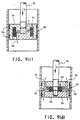
- FIG. 10(a) -(c) each employ a twin-tube housing 20 which allow the coil 40 to be located stationarily relative to the housing.
- Housing 20 has a first inner tube 17 and a second outer tube 19 .
- Valve member 59 comprises coil 40 which is wrapped around core element 43 and the end of inner tube 17 is stabilized between core element 43 and cup-shaped end member 53 by spacers (not shown) to define the gap g of valve member 59 .
- Accumulator 23 is incorporated into piston head 34 .
- a floating piston 21 can be used to create the accumulator 23 or, as mentioned with respect to earlier embodiments, a rolling diaphragm of a type similar to that taught in U. S. Patent No. 4,811,919, which is hereby incorporated by reference, may be used. Any type of accumulator may be used.
- the MR fluid is a) forced through gap g , which (in conjunction with coil 40 ) functions as a valve, b) into outer tube 19 , c) through openings 68 back into the inner tube 17 .
- the flow characteristics of MR fluid 18 will be controlled by regulating the current flow in coil 40 , as with previous embodiments.
- Fig. 10(b) shows a similar twin tube housing 20 in which coil 40 is toroidally wound about core 43 in segments with intermittent slots as in the Fig. 8 embodiment.
- the slots, in conjunction with the coil 40 will function as the valve for the MR fluid 18 in this embodiment.
- Fig. 10(c) demonstrates a third embodiment of a damper 16 which has a twin tube housing 20 .
- two coils 40 are used, the lower coil 40 and gap g 1 form the valve for controlling flow of the compressive stroke while upper coil 40 and gap g 2 form the valve for controlling flow on the extension stroke.
- Lower valve member 59 is depicted as having a baffle plate 58 , while upper valve member 59 , which must permit passage of piston rod 32 , is of a modified solenoidal design.
- Upper and lower check valves 35 which are preferably reed valves that flap open and closed responsive to fluid pressure, provide fluid bypass of upper and lower coils 40 for the compression and extension strokes, respectively.
- An externally mounted accumulator 23 of the type shown in U. S. patent no, 4,858,898 is used in this embodiment which comprises an elastomeric bladder that may be filled with air or foam rubber.
- accumulator 23 provides room for additional incompreasible MR fluid resulting from displacement by piston rod 32 or from thermal fluid expansion.
- no electrical connections are made through piston rod 32 and piston head 34 has a more conventional engagement with inner tube 17 (i.e., no fluid flow past or through).
- Recesses 37 form pockets which in conjunction with hydraulic end stops 31 trap fluid and prevent piston head 34 from banging into either end cap 64 .
- This double-valve design is particularly useful for dampers generating large forces. In such applications, the use of two valves 59 provides more precise control and reduces the risk of cavitation of the fluid. Further, the forces generated in the compression and extension strokes can be individually tailored to fit the desired design parameters.
- Figs. 11(a) - 11(c) depict three embodiments of sealless dampers 16 .
- One problem with the conventional damper design is preventing loss of the MR fluid which would result in diminished performance.
- Previously described embodiments have proposed the use of a secondary fluid with a combination scraper and seal to cope with this problem.
- a secondary problem is the need for an accumulator with the conventional designs to provide for fluid displaced by piston rod.
- the piston rod 32 extends above and below piston head 34 and has elastomer elements 70 and 72 which may be of frustoconical design, bonded to its upper and lower extents, respectively.
- Elastomer elements 70 , 72 are also bonded to housing 20 trapping a fixed volume of fluid 18 . An accumulator is unnecessary since there is no fluid displaced by piston rod 32 which cannot be accommodated by the volume on the opposite side of piston head 34 . Depending on the bulge stiffness of the elastomer, the elements 70 and 72 can accommodate thermal expansion of the fluid. Electrical connection is made to coil 40 through shaft 32 , as in earlier embodiments. Ears 74 (Fig. 11(a)) provide means for attaching housing 20 to one of the two elements to be isolated with piston rod 32 being attachable to the other.
- Fig. 11(b) affords a means of providing greater resistance to compressive forces than to extension forces by pressurizing (or charging) chamber 76 .
- Fig. 11(c) shows a third sealless embodiment designed to provide extended stroke.
- damper 16 is shown at the completion of a compression stroke.
- Disc shaped elastomer 70 is bonded at its outer extremity to a ring 77 which sits atop the inner cylinder of housing 20 and its inner periphery is bonded to element 80 , which is preferably metallic.
- element 80 which is preferably metallic.
- the upper inner periphery of element 80 slides freely relative to piston rod 32 by virtue of bearing 82 .
- the lower inner periphery of element 80 is bonded to the outside of disc-shaped elastomer 71 whose inner periphery is bonded to cylindrical sleeve 75 .
- Sleeve 75 moves with piston rod 32 but its use (being separable therefrom) facilitates manufacture.
- a second element 80 has the outer periphery of-disc-shaped elastomer 72 bonded to its inner upper periphery.
- the inner periphery of disc 72 is bonded to piston rod extension 33 .
- a fourth disc-shaped elastomer element 73 is bonded to the outer lower periphery of second element 80 and to ring 78 which is trapped between portions of housing 20 and, functionally, becomes a part thereof.
- This embodiment permits the throw length of damper 16 to be extended and, obviously, additional throw length could be added as necessary by stacking additional elements 80 with associated disc-shaped elastomers 70-73 .
- FIG. 12(a) and 12(b) A pair of mounts employing the features of the present invention are depicted in Figs. 12(a) and 12(b) generally at 86 .
- the embodiment of mount 86 in Fig. 12(a) has a baffle plate 58 which is held in place by snap-in spacers 89 , and a solenoid-type coil 40 wrapped within housing 20 .
- Spacers 89 are made of a non-magnetic, preferably plastic material.
- Baffle plate 58 diverts the flow of the MR fluid into more intimate contact with coil 40 enhancing the flow control of the fluid by increasing the capability of the coil to influence the characteristics of the fluid.
- a first pair of bolts 91 provide means for attachment to a first member (a frame, or the like) and bolt 93 provides means for attachment to a second member (an engine, for example).
- Elastomeric element 90 is bonded to both attachment collar 88 and housing 20 and comprises the primary spring in the mount 86 .
- Collar 88, elastomeric element 90 and upper surface of housing 92 for baffle plate 58 define a first chamber 94 for containing MR fluid.
- the lower surface of housing 92 and an elastomeric bladder 95 (which forms the bottom compliance of mount 86 ) define a second chamber 96 for MR fluid.
- the orifices 98 in housing 92 operate with coil 40 to define a valve for controlling the flow of the MR fluid, as in previous embodiments.
- the radial extent of orifices 98 is a design parameter which may be adjusted to influence operational characteristics of the mount 86 .
- Fig. 12(b) The embodiment shown in Fig. 12(b) is similar to that shown in Fig. 12(a) in all particulars with the exception that the coil 40 is of the toroidal type with slots 52 serving as the fluid control valve as with the twin tube design depicted in Figs. 10(b) .
- the slots 52 serve as means to increase exposure of the MR fluid to the coil 40 , thereby enhancing flow control.
- No baffle plate is necessary with this design, so a solid divider plate 58a is substituted.
- the mounts 86 of Figs. 12(a) and 12(b) allow the stiffness of the mount to be controlled in response to operational characteristics of the engine (idle vs high rpm), or vehicle (cornering or straight runs) by use of electronic sensors and control signals giving input to the energy supply of coil 40 , in a conventional manner.
- the present invention provides a number of embodiments of an MR fluid damper with a variety of novel characteristics.
- a first embodiment optimizes the dimensional and operational parameters of the damper to provide a high level of controllability.
- a second embodiment provides an alternate piston head with a toroidally wound magnet incorporated therein.
- Third through sixth embodiments provide piston heads with fluid flow therethrough (rather than therearound) and the magnetic flux path contained entirely within the piston head.
- a series of seventh through ninth embodiments provide alternate housing configurations in which the flow control magnet is associated with the housing, including one embodiment in which an upper and a lower flow control valve is used.
- Tenth trough twelfth damper embodiments teach sealless dampers which eliminate loss of MR fluids and, finally, two MR fluid mount designs employing the features of the present invention are described.
Applications Claiming Priority (5)
| Application Number | Priority Date | Filing Date | Title |
|---|---|---|---|
| US900571 | 1992-06-18 | ||
| US07/900,571 US5277281A (en) | 1992-06-18 | 1992-06-18 | Magnetorheological fluid dampers |
| US07/900,567 US5284330A (en) | 1992-06-18 | 1992-06-18 | Magnetorheological fluid devices |
| US900567 | 1992-06-18 | ||
| EP93916607A EP0644987B1 (fr) | 1992-06-18 | 1993-06-18 | Dispositif a fluides magnetorheologiques |
Related Parent Applications (1)
| Application Number | Title | Priority Date | Filing Date |
|---|---|---|---|
| EP93916607A Division EP0644987B1 (fr) | 1992-06-18 | 1993-06-18 | Dispositif a fluides magnetorheologiques |
Publications (3)
| Publication Number | Publication Date |
|---|---|
| EP1016805A2 true EP1016805A2 (fr) | 2000-07-05 |
| EP1016805A3 EP1016805A3 (fr) | 2000-11-02 |
| EP1016805B1 EP1016805B1 (fr) | 2003-04-09 |
Family
ID=27129267
Family Applications (4)
| Application Number | Title | Priority Date | Filing Date |
|---|---|---|---|
| EP00105844A Expired - Lifetime EP1013963B1 (fr) | 1992-06-18 | 1993-06-18 | Dispositif à fluides magnétorhéologiques |
| EP00105842A Expired - Lifetime EP1016805B1 (fr) | 1992-06-18 | 1993-06-18 | Dispositifs à fluide magnétorhéologique |
| EP93916607A Expired - Lifetime EP0644987B1 (fr) | 1992-06-18 | 1993-06-18 | Dispositif a fluides magnetorheologiques |
| EP00105843A Expired - Lifetime EP1016806B1 (fr) | 1992-06-18 | 1993-06-18 | Dispositifs à fluide magnétorhéologique |
Family Applications Before (1)
| Application Number | Title | Priority Date | Filing Date |
|---|---|---|---|
| EP00105844A Expired - Lifetime EP1013963B1 (fr) | 1992-06-18 | 1993-06-18 | Dispositif à fluides magnétorhéologiques |
Family Applications After (2)
| Application Number | Title | Priority Date | Filing Date |
|---|---|---|---|
| EP93916607A Expired - Lifetime EP0644987B1 (fr) | 1992-06-18 | 1993-06-18 | Dispositif a fluides magnetorheologiques |
| EP00105843A Expired - Lifetime EP1016806B1 (fr) | 1992-06-18 | 1993-06-18 | Dispositifs à fluide magnétorhéologique |
Country Status (5)
| Country | Link |
|---|---|
| EP (4) | EP1013963B1 (fr) |
| AU (2) | AU671848B2 (fr) |
| CA (1) | CA2138549C (fr) |
| DE (4) | DE69332867T2 (fr) |
| WO (1) | WO1994000704A1 (fr) |
Cited By (4)
| Publication number | Priority date | Publication date | Assignee | Title |
|---|---|---|---|---|
| US7556140B2 (en) | 2006-08-31 | 2009-07-07 | Martin Engineering Company | Bulk material handling system |
| US7669708B2 (en) | 2006-08-31 | 2010-03-02 | Martin Engineering Company | Bulk material handling system and control |
| US8205741B2 (en) | 2010-08-06 | 2012-06-26 | Martin Engineering Company | Method of adjusting conveyor belt scrapers and open loop control system for conveyor belt scrapers |
| CN103527703A (zh) * | 2013-10-25 | 2014-01-22 | 重庆大学 | 自供电磁流变减振器 |
Families Citing this family (37)
| Publication number | Priority date | Publication date | Assignee | Title |
|---|---|---|---|---|
| DE4433056C2 (de) * | 1994-09-16 | 1998-01-29 | Mannesmann Sachs Ag | Schwingungsdämpfer für Kraftfahrzeuge |
| US5878851A (en) * | 1996-07-02 | 1999-03-09 | Lord Corporation | Controllable vibration apparatus |
| US6312049B1 (en) * | 1999-07-01 | 2001-11-06 | Ford Global Technologies, Inc. | Programmable seat back damper assembly for seats |
| GB9920311D0 (en) * | 1999-08-28 | 1999-11-03 | Stangroom James E | Improvements in or relating to linear dampers controlled by electro-rheological fluids |
| DE29922856U1 (de) * | 1999-12-27 | 2000-05-04 | Trw Repa Gmbh | Fahrzeugsitz |
| DE10013586A1 (de) * | 2000-03-18 | 2001-09-20 | Bayerische Motoren Werke Ag | Wendel- oder Spiralfeder |
| DE10030079A1 (de) * | 2000-06-19 | 2002-01-24 | Schenck Ag Carl | Zylinder-Kolben-Anordnung auf Basis elektrorheologischer/magnetorheologischer Flüssigkeiten |
| FR2818304B1 (fr) | 2000-12-15 | 2003-09-05 | Renault | Dispositif pour immobilier un ouvrant de vehicule automobile |
| US20020139624A1 (en) * | 2001-03-30 | 2002-10-03 | Jensen Eric Lee | Twin-tube magnetorheological damper |
| DE10155587C1 (de) * | 2001-11-13 | 2003-05-15 | Continental Ag | Lager mit magneto-rheologisch einstellbarer Dämpferkraft |
| DE10337516B9 (de) * | 2003-08-14 | 2015-08-27 | Eto Magnetic Gmbh | Ventilanordnung zur Regulierung des Fließverhaltens einer magnetorheologischen Flüssigkeit |
| DE102004043281A1 (de) * | 2004-09-08 | 2006-03-09 | Fludicon Gmbh | Vorrichtung zum Fixieren von beweglich gelagerten Teilen |
| DE102004052573A1 (de) * | 2004-10-29 | 2006-05-11 | Fraunhofer-Gesellschaft zur Förderung der angewandten Forschung e.V. | Einrichtung zur Dämpfung von Schwingungen und/oder Stössen |
| US7303056B2 (en) * | 2004-12-09 | 2007-12-04 | General Motors Corporation | Magnetorheological device and system and method for using the same |
| DE102005013986B3 (de) * | 2005-03-26 | 2006-06-14 | Festo Ag & Co. | Fluidvorrichtung mit magnetorheologischer Flüssigkeit |
| US20060260891A1 (en) * | 2005-05-17 | 2006-11-23 | Kruckemeyer William C | Magnetorheological piston assembly and damper |
| CN100340794C (zh) * | 2005-08-04 | 2007-10-03 | 浙江大学 | 微型汽车的磁流变智能减振器 |
| WO2007130966A2 (fr) * | 2006-05-01 | 2007-11-15 | Lord Corporation | Système de suspension de véhicule contrôlable à entretoise à fluide magnétorhéologique contrôlable |
| WO2008133720A1 (fr) * | 2007-05-01 | 2008-11-06 | Lord Corporation | Système de suspension de véhicule commandable comprenant un dispositif à fluide magnétorhéologique |
| US7849983B2 (en) * | 2006-05-01 | 2010-12-14 | Lord Corporation | Controllable vehicle suspension system with a controllable magnetorheological fluid strut |
| US8322497B2 (en) | 2006-05-01 | 2012-12-04 | Lord Corporation | Magneto-rheological dampers for semi-active suspension systems |
| JP2010501839A (ja) * | 2006-08-23 | 2010-01-21 | ビーエーエスエフ ソシエタス・ヨーロピア | 磁気流動流体のための連続負荷せん断セル |
| EP2057457A1 (fr) | 2006-08-23 | 2009-05-13 | Basf Se | Rhéomètre |
| WO2008034820A1 (fr) | 2006-09-22 | 2008-03-27 | Basf Se | Formulation magnétorhéologique |
| DE102007040600B4 (de) | 2007-08-27 | 2012-12-06 | Zf Friedrichshafen Ag | Steuerbares Hydrolager |
| EP2434154A1 (fr) * | 2010-09-28 | 2012-03-28 | Siemens Aktiengesellschaft | Agencement d'amortissement actif d'éolienne |
| CN102102731B (zh) * | 2011-02-28 | 2012-08-01 | 重庆大学 | 基于磁流变体的解耦型阻尼和刚度可控油气弹簧减振装置 |
| CN102162499B (zh) * | 2011-03-04 | 2016-03-30 | 海尔集团公司 | 一种变阻尼减震器及使用这种减震器的滚筒洗衣机 |
| CN102207162B (zh) * | 2011-06-13 | 2012-08-01 | 谭晓婧 | 叠片活塞单出杆磁流变阻尼器 |
| RU2506476C1 (ru) * | 2012-05-28 | 2014-02-10 | Федеральное государственное бюджетное образовательное учреждение высшего профессионального образования "Ивановский государственный энергетический университет имени В.И. Ленина" (ИГЭУ) | Поршневой магнитожидкостный амортизатор |
| CN103032510B (zh) * | 2012-12-12 | 2016-06-01 | 重庆大学 | 拉伸型磁流变缓冲器 |
| CN103396655B (zh) * | 2013-08-14 | 2015-12-02 | 株洲时代新材料科技股份有限公司 | 一种磁流变阻尼器用灌封胶及其制备和使用方法 |
| CN104595413B (zh) * | 2015-01-08 | 2016-08-24 | 重庆材料研究院有限公司 | 多层阻尼通道式磁控减振器 |
| CN105292047B (zh) * | 2015-10-12 | 2017-11-24 | 上海工程技术大学 | 磁流变限力器控制的安全带 |
| CN106246796B (zh) * | 2016-08-10 | 2017-12-22 | 安徽工程大学 | 一种汽车悬架自供电磁流变阻尼器装置 |
| CN109899437B (zh) * | 2017-12-07 | 2024-03-05 | 陕西汽车集团股份有限公司 | 振动能量回收型磁流变减振器 |
| CN111963742B (zh) * | 2020-08-11 | 2022-04-15 | 开平市中奥卫浴有限公司 | 一种流速可调的延时水龙头 |
Citations (5)
| Publication number | Priority date | Publication date | Assignee | Title |
|---|---|---|---|---|
| FR1094516A (fr) * | 1953-11-25 | 1955-05-20 | Piston d'amortisseur hydraulique | |
| US3059915A (en) * | 1961-06-21 | 1962-10-23 | Robert E Kemelhor | Unitary fluid magnetic spring, shock and lockout device |
| JPS58221034A (ja) * | 1982-06-16 | 1983-12-22 | Showa Mfg Co Ltd | 油圧緩衝器における減衰力調整装置 |
| JPS59184007A (ja) * | 1983-03-31 | 1984-10-19 | Nhk Spring Co Ltd | 車輛用懸架装置 |
| JPS62251539A (ja) * | 1986-04-22 | 1987-11-02 | Honda Motor Co Ltd | 電気流動流体ダンパのための高電圧印加装置 |
Family Cites Families (26)
| Publication number | Priority date | Publication date | Assignee | Title |
|---|---|---|---|---|
| US2661596A (en) | 1950-01-28 | 1953-12-08 | Wefco Inc | Field controlled hydraulic device |
| FR1037787A (fr) * | 1951-05-28 | 1953-09-22 | Amortisseur, notamment pour véhicules | |
| US3174587A (en) * | 1964-03-12 | 1965-03-23 | Walton Marvin | Adjustable shock absorber |
| FR1414841A (fr) * | 1964-08-10 | 1965-10-22 | Amortisseur télescopique | |
| DE2727244C2 (de) * | 1976-06-30 | 1990-06-21 | Automobiles Peugeot, 75116 Paris | Gummifeder mit Flüssigkeitsfüllung |
| ZA784514B (en) * | 1978-08-09 | 1980-01-30 | South African Inventions | Damper device |
| US4236607A (en) * | 1979-02-26 | 1980-12-02 | Textron, Inc. | Vibration suppression system |
| JPS57129944A (en) * | 1981-02-06 | 1982-08-12 | Aisin Seiki Co Ltd | Magnetic fluid damper |
| DE3128723A1 (de) * | 1981-07-21 | 1983-02-10 | Fichtel & Sachs Ag, 8720 Schweinfurt | Hydropneumatischer zweirohr-schwingungsdaempfer oder federbeineinsatz mit einer verschlusskappe fuer ein behaelterrohr |
| JPS58113644A (ja) * | 1981-12-25 | 1983-07-06 | Aisin Seiki Co Ltd | 磁性流体式ダンパ− |
| JPS5969543A (ja) * | 1982-10-13 | 1984-04-19 | Nissan Motor Co Ltd | シヨツクアブソ−バ |
| GB8316419D0 (en) * | 1983-06-16 | 1983-07-20 | Dunlop Ltd | Spring |
| JPS60113711A (ja) * | 1983-11-22 | 1985-06-20 | Honda Motor Co Ltd | サスペンシヨンダンパ− |
| US4724937A (en) * | 1984-09-04 | 1988-02-16 | General Motors Corporation | Hydraulic damper for vehicles with variable deflected disk piston valving |
| FR2579283B1 (fr) * | 1985-03-19 | 1989-06-16 | Renault | Amortisseur de vibrations electromagnetique |
| US4742998A (en) * | 1985-03-26 | 1988-05-10 | Barry Wright Corporation | Active vibration isolation system employing an electro-rheological fluid |
| US4890822A (en) * | 1986-02-13 | 1990-01-02 | Nhk Spring Co., Ltd. | Car suspension system |
| JPS631833A (ja) * | 1986-06-20 | 1988-01-06 | Tokai Rubber Ind Ltd | 流体封入式防振支持装置 |
| JPS63231031A (ja) * | 1987-03-19 | 1988-09-27 | Nkk Corp | 可変減衰力ダンパ |
| FR2634530A1 (en) * | 1988-07-19 | 1990-01-26 | Hutchinson | Improvements to hydraulic anti-vibration devices |
| JPH0781605B2 (ja) * | 1989-02-01 | 1995-09-06 | 東海ゴム工業株式会社 | 電気粘性流体使用装置 |
| JPH02225837A (ja) * | 1989-02-27 | 1990-09-07 | Bridgestone Corp | 防振装置 |
| US5070972A (en) * | 1990-06-18 | 1991-12-10 | General Motors Corporation | Vortex valving assembly for a hydraulic damper |
| DE4019578A1 (de) * | 1990-06-20 | 1992-01-02 | Stabilus Gmbh | Hydraulisches, pneumatisches oder hydropneumatisches aggregat mit reibkraftunterstuetzung durch selbstklemmende reibelemente |
| JPH04175533A (ja) * | 1990-11-05 | 1992-06-23 | Nissan Motor Co Ltd | 圧電アクチュエータの変位拡大機構 |
| US5176368A (en) * | 1992-01-13 | 1993-01-05 | Trw Inc. | Vehicle engine mount |
-
1993
- 1993-06-18 EP EP00105844A patent/EP1013963B1/fr not_active Expired - Lifetime
- 1993-06-18 EP EP00105842A patent/EP1016805B1/fr not_active Expired - Lifetime
- 1993-06-18 DE DE1993632867 patent/DE69332867T2/de not_active Expired - Lifetime
- 1993-06-18 EP EP93916607A patent/EP0644987B1/fr not_active Expired - Lifetime
- 1993-06-18 AU AU46403/93A patent/AU671848B2/en not_active Ceased
- 1993-06-18 DE DE1993632868 patent/DE69332868T2/de not_active Expired - Lifetime
- 1993-06-18 WO PCT/US1993/005835 patent/WO1994000704A1/fr active IP Right Grant
- 1993-06-18 CA CA002138549A patent/CA2138549C/fr not_active Expired - Fee Related
- 1993-06-18 DE DE69329851T patent/DE69329851T2/de not_active Expired - Lifetime
- 1993-06-18 EP EP00105843A patent/EP1016806B1/fr not_active Expired - Lifetime
- 1993-06-18 DE DE1993633172 patent/DE69333172T2/de not_active Expired - Fee Related
-
1996
- 1996-07-11 AU AU59466/96A patent/AU684687B2/en not_active Ceased
Patent Citations (5)
| Publication number | Priority date | Publication date | Assignee | Title |
|---|---|---|---|---|
| FR1094516A (fr) * | 1953-11-25 | 1955-05-20 | Piston d'amortisseur hydraulique | |
| US3059915A (en) * | 1961-06-21 | 1962-10-23 | Robert E Kemelhor | Unitary fluid magnetic spring, shock and lockout device |
| JPS58221034A (ja) * | 1982-06-16 | 1983-12-22 | Showa Mfg Co Ltd | 油圧緩衝器における減衰力調整装置 |
| JPS59184007A (ja) * | 1983-03-31 | 1984-10-19 | Nhk Spring Co Ltd | 車輛用懸架装置 |
| JPS62251539A (ja) * | 1986-04-22 | 1987-11-02 | Honda Motor Co Ltd | 電気流動流体ダンパのための高電圧印加装置 |
Non-Patent Citations (3)
| Title |
|---|
| PATENT ABSTRACTS OF JAPAN vol. 008, no. 076 (M-288), 9 April 1984 (1984-04-09) & JP 58 221034 A (SHIYOUWA SEISAKUSHO:KK), 22 December 1983 (1983-12-22) * |
| PATENT ABSTRACTS OF JAPAN vol. 009, no. 042 (M-359), 22 February 1985 (1985-02-22) & JP 59 184007 A (NIHON HATSUJIYOU KK), 19 October 1984 (1984-10-19) * |
| PATENT ABSTRACTS OF JAPAN vol. 012, no. 126 (M-687), 19 April 1988 (1988-04-19) & JP 62 251539 A (HONDA MOTOR CO LTD), 2 November 1987 (1987-11-02) * |
Cited By (9)
| Publication number | Priority date | Publication date | Assignee | Title |
|---|---|---|---|---|
| US7556140B2 (en) | 2006-08-31 | 2009-07-07 | Martin Engineering Company | Bulk material handling system |
| US7669708B2 (en) | 2006-08-31 | 2010-03-02 | Martin Engineering Company | Bulk material handling system and control |
| US7740126B2 (en) | 2006-08-31 | 2010-06-22 | Martin Engineering Company | Bulk material handling system |
| US7740127B2 (en) | 2006-08-31 | 2010-06-22 | Martin Engineering Company | Bulk material handling system |
| US7775341B2 (en) | 2006-08-31 | 2010-08-17 | Martin Engineering Company | Bulk material handling system |
| US8037997B2 (en) | 2006-08-31 | 2011-10-18 | Martin Engineering Company | Bulk material handling system and control |
| US8069971B2 (en) | 2006-08-31 | 2011-12-06 | Martin Engineering Company | Bulk material handling system and control |
| US8205741B2 (en) | 2010-08-06 | 2012-06-26 | Martin Engineering Company | Method of adjusting conveyor belt scrapers and open loop control system for conveyor belt scrapers |
| CN103527703A (zh) * | 2013-10-25 | 2014-01-22 | 重庆大学 | 自供电磁流变减振器 |
Also Published As
| Publication number | Publication date |
|---|---|
| AU684687B2 (en) | 1997-12-18 |
| AU671848B2 (en) | 1996-09-12 |
| DE69332867T2 (de) | 2003-12-11 |
| DE69333172D1 (de) | 2003-10-02 |
| DE69329851D1 (de) | 2001-02-15 |
| AU5946696A (en) | 1996-09-05 |
| DE69329851T2 (de) | 2001-05-23 |
| EP0644987A4 (fr) | 1997-12-17 |
| EP1013963A2 (fr) | 2000-06-28 |
| EP1013963B1 (fr) | 2003-08-27 |
| EP1016805A3 (fr) | 2000-11-02 |
| WO1994000704A1 (fr) | 1994-01-06 |
| EP0644987A1 (fr) | 1995-03-29 |
| EP1016806A3 (fr) | 2000-11-02 |
| EP1016806B1 (fr) | 2003-04-09 |
| DE69333172T2 (de) | 2004-06-17 |
| EP0644987B1 (fr) | 2001-01-10 |
| DE69332868T2 (de) | 2003-12-11 |
| DE69332867D1 (de) | 2003-05-15 |
| EP1016806A2 (fr) | 2000-07-05 |
| EP1013963A3 (fr) | 2000-11-02 |
| EP1016805B1 (fr) | 2003-04-09 |
| CA2138549A1 (fr) | 1994-01-06 |
| CA2138549C (fr) | 2001-12-18 |
| DE69332868D1 (de) | 2003-05-15 |
| AU4640393A (en) | 1994-01-24 |
Similar Documents
| Publication | Publication Date | Title |
|---|---|---|
| EP0644987B1 (fr) | Dispositif a fluides magnetorheologiques | |
| US5398917A (en) | Magnetorheological fluid devices | |
| US5277281A (en) | Magnetorheological fluid dampers | |
| US11279198B2 (en) | Methods and apparatus for controlling a fluid damper | |
| US6419058B1 (en) | Magnetorheological damper with piston bypass | |
| US6279701B1 (en) | Magnetorheological fluid damper with multiple annular flow gaps | |
| US6874603B2 (en) | Magnetorheological piston and damper assembly | |
| US6497309B1 (en) | Magneto-rheological damper with an external coil | |
| US4946009A (en) | Electromagnetic valve utilizing a permanent magnet | |
| US11015672B2 (en) | Smart fluid damper | |
| US6637557B2 (en) | Magnetorheological strut piston with compression bypass | |
| US20010050202A1 (en) | Magnetorheological fluid damper tunable for smooth transitions | |
| US20040118646A1 (en) | Magnetorheological damper assembly and piston | |
| CN113027978B (zh) | 多环路非对称式磁流变阻尼器 | |
| JPS6210514Y2 (fr) | ||
| CA2984533C (fr) | Amortisseur a fluide intelligent |
Legal Events
| Date | Code | Title | Description |
|---|---|---|---|
| PUAI | Public reference made under article 153(3) epc to a published international application that has entered the european phase |
Free format text: ORIGINAL CODE: 0009012 |
|
| 17P | Request for examination filed |
Effective date: 20000418 |
|
| AC | Divisional application: reference to earlier application |
Ref document number: 644987 Country of ref document: EP |
|
| AK | Designated contracting states |
Kind code of ref document: A2 Designated state(s): DE FR GB IT |
|
| PUAL | Search report despatched |
Free format text: ORIGINAL CODE: 0009013 |
|
| AK | Designated contracting states |
Kind code of ref document: A3 Designated state(s): DE FR GB IT |
|
| RIC1 | Information provided on ipc code assigned before grant |
Free format text: 7F 16F 9/53 A, 7F 16F 13/30 B |
|
| AKX | Designation fees paid |
Free format text: DE FR GB IT |
|
| 17Q | First examination report despatched |
Effective date: 20020103 |
|
| GRAH | Despatch of communication of intention to grant a patent |
Free format text: ORIGINAL CODE: EPIDOS IGRA |
|
| GRAH | Despatch of communication of intention to grant a patent |
Free format text: ORIGINAL CODE: EPIDOS IGRA |
|
| GRAA | (expected) grant |
Free format text: ORIGINAL CODE: 0009210 |
|
| RIN1 | Information on inventor provided before grant (corrected) |
Inventor name: JAMES, FRANK O. Inventor name: CARLSON, J. DAVID Inventor name: CHRZAN, MICHAEL, J. |
|
| AC | Divisional application: reference to earlier application |
Ref document number: 0644987 Country of ref document: EP Kind code of ref document: P |
|
| AK | Designated contracting states |
Designated state(s): DE FR GB IT |
|
| REG | Reference to a national code |
Ref country code: GB Ref legal event code: FG4D |
|
| PGFP | Annual fee paid to national office [announced via postgrant information from national office to epo] |
Ref country code: GB Payment date: 20030611 Year of fee payment: 11 |
|
| ET | Fr: translation filed | ||
| PLBE | No opposition filed within time limit |
Free format text: ORIGINAL CODE: 0009261 |
|
| STAA | Information on the status of an ep patent application or granted ep patent |
Free format text: STATUS: NO OPPOSITION FILED WITHIN TIME LIMIT |
|
| 26N | No opposition filed |
Effective date: 20040112 |
|
| PG25 | Lapsed in a contracting state [announced via postgrant information from national office to epo] |
Ref country code: GB Free format text: LAPSE BECAUSE OF NON-PAYMENT OF DUE FEES Effective date: 20040618 |
|
| GBPC | Gb: european patent ceased through non-payment of renewal fee |
Effective date: 20040618 |
|
| PGFP | Annual fee paid to national office [announced via postgrant information from national office to epo] |
Ref country code: FR Payment date: 20080617 Year of fee payment: 16 Ref country code: IT Payment date: 20080627 Year of fee payment: 16 |
|
| REG | Reference to a national code |
Ref country code: FR Ref legal event code: ST Effective date: 20100226 |
|
| PG25 | Lapsed in a contracting state [announced via postgrant information from national office to epo] |
Ref country code: FR Free format text: LAPSE BECAUSE OF NON-PAYMENT OF DUE FEES Effective date: 20090630 |
|
| PG25 | Lapsed in a contracting state [announced via postgrant information from national office to epo] |
Ref country code: IT Free format text: LAPSE BECAUSE OF NON-PAYMENT OF DUE FEES Effective date: 20090618 |
|
| PGFP | Annual fee paid to national office [announced via postgrant information from national office to epo] |
Ref country code: DE Payment date: 20120627 Year of fee payment: 20 |
|
| REG | Reference to a national code |
Ref country code: DE Ref legal event code: R071 Ref document number: 69332867 Country of ref document: DE |
|
| PG25 | Lapsed in a contracting state [announced via postgrant information from national office to epo] |
Ref country code: DE Free format text: LAPSE BECAUSE OF EXPIRATION OF PROTECTION Effective date: 20130619 |