EP1016705B1 - Brenner für die partielle Oxidation von flüssigen, kohlenstoffhaltigen Brennstoffen - Google Patents
Brenner für die partielle Oxidation von flüssigen, kohlenstoffhaltigen Brennstoffen Download PDFInfo
- Publication number
- EP1016705B1 EP1016705B1 EP99121717A EP99121717A EP1016705B1 EP 1016705 B1 EP1016705 B1 EP 1016705B1 EP 99121717 A EP99121717 A EP 99121717A EP 99121717 A EP99121717 A EP 99121717A EP 1016705 B1 EP1016705 B1 EP 1016705B1
- Authority
- EP
- European Patent Office
- Prior art keywords
- mixing chamber
- burner
- tube
- chamber
- opening
- Prior art date
- Legal status (The legal status is an assumption and is not a legal conclusion. Google has not performed a legal analysis and makes no representation as to the accuracy of the status listed.)
- Expired - Lifetime
Links
Images
Classifications
-
- C—CHEMISTRY; METALLURGY
- C01—INORGANIC CHEMISTRY
- C01B—NON-METALLIC ELEMENTS; COMPOUNDS THEREOF; METALLOIDS OR COMPOUNDS THEREOF NOT COVERED BY SUBCLASS C01C
- C01B3/00—Hydrogen; Gaseous mixtures containing hydrogen; Separation of hydrogen from mixtures containing it; Purification of hydrogen; Reversible storage of hydrogen
- C01B3/02—Production of hydrogen; Production of gaseous mixtures containing hydrogen
- C01B3/32—Production of hydrogen; Production of gaseous mixtures containing hydrogen by reaction of gaseous or liquid organic compounds with gasifying agents, e.g. water, carbon dioxide or air
- C01B3/34—Production of hydrogen; Production of gaseous mixtures containing hydrogen by reaction of gaseous or liquid organic compounds with gasifying agents, e.g. water, carbon dioxide or air by reaction of hydrocarbons with gasifying agents
- C01B3/36—Production of hydrogen; Production of gaseous mixtures containing hydrogen by reaction of gaseous or liquid organic compounds with gasifying agents, e.g. water, carbon dioxide or air by reaction of hydrocarbons with gasifying agents using oxygen; using mixtures containing oxygen as gasifying agents
- C01B3/363—Production of hydrogen; Production of gaseous mixtures containing hydrogen by reaction of gaseous or liquid organic compounds with gasifying agents, e.g. water, carbon dioxide or air by reaction of hydrocarbons with gasifying agents using oxygen; using mixtures containing oxygen as gasifying agents characterised by the burner
-
- F—MECHANICAL ENGINEERING; LIGHTING; HEATING; WEAPONS; BLASTING
- F23—COMBUSTION APPARATUS; COMBUSTION PROCESSES
- F23D—BURNERS
- F23D11/00—Burners using a direct spraying action of liquid droplets or vaporised liquid into the combustion space
- F23D11/10—Burners using a direct spraying action of liquid droplets or vaporised liquid into the combustion space the spraying being induced by a gaseous medium, e.g. water vapour
- F23D11/101—Burners using a direct spraying action of liquid droplets or vaporised liquid into the combustion space the spraying being induced by a gaseous medium, e.g. water vapour medium and fuel meeting before the burner outlet
- F23D11/102—Burners using a direct spraying action of liquid droplets or vaporised liquid into the combustion space the spraying being induced by a gaseous medium, e.g. water vapour medium and fuel meeting before the burner outlet in an internal mixing chamber
-
- F—MECHANICAL ENGINEERING; LIGHTING; HEATING; WEAPONS; BLASTING
- F23—COMBUSTION APPARATUS; COMBUSTION PROCESSES
- F23D—BURNERS
- F23D23/00—Assemblies of two or more burners
Definitions
- the invention relates to a burner for the partial Oxidation of liquid, carbonaceous fuel with Water vapor and an oxygen-containing gas, wherein the Exit port of the burner directed into a combustion chamber is.
- Burners of this type are known and z.
- EP 0 127 273 B1 in US Pat. No. 4,933,163 and in US Pat EP-0 707 880 A1. From the latter Publication is also the arrangement of such Brenners known at the entrance of an empty combustion chamber, being the crude product gas produced then cleaned and z. B. is further processed to a synthesis gas.
- the invention has for its object to provide a burner for the partial oxidation of liquid fuels, such.
- a burner for the partial oxidation of liquid fuels, such.
- As heavy oil to provide, in which the fuel first broken into fine droplets and intensively with Water vapor is mixed before the mixture with the Oxygen comes in contact.
- this is achieved by the burner in the vicinity of the Outlet mouth a conical, to the outlet mouth towards expanding mixing chamber that a liquid Fuel in the mixing chamber feeding first tube is arranged coaxially with the mixing chamber, wherein the Mouth of the first pipe in the area of the entrance end the mixing chamber is located and between the mouth end of the first tube and the inlet end of the mixing chamber
- Annular gap for the passage of water vapor is that a first annular chamber for the passage of water vapor surrounding the first pipe and connected to the annular gap, that a second tube surrounds the first annular chamber and sealed against the outside of the mixing chamber that a second annular chamber for the passage of oxygen-containing gas to the outlet of the burner surrounding the
- carbonaceous fuel z As a liquid, carbonaceous fuel z.
- heavy oil a pumpable slurry granular coal or petroleum coke in water or in liquid hydrocarbons, as well as an emulsion of bitumen or asphalt in water in question.
- O 2 -containing gas is usually used technically pure oxygen or oxygen-enriched air, if the nitrogen content does not interfere.
- the pressure in the combustion chamber, in which the burner upcoming mixture is partially oxidized is usually in the range of 1 to 100 bar.
- the burner of FIG. 1 the liquid Hydrocarbons by means of a pump, not shown through the central first tube (1) into the conical Mixing chamber (2) pressed and thereby to fine droplets divided.
- the mouth end (1a) of the first tube is located in the region of the inlet end (2a) of the mixing chamber, wherein an annular gap (3) for the passage of water vapor consists.
- the steam comes from a first annular chamber (5), the the first tube (1) surrounds, he first flows between a second tube (6) and the outside of a Connecting sleeve (7) through the openings (8) (see Also Fig. 2) to the annular gap (3) and then into the mixing chamber (2).
- the mixing chamber serves to intensive mixing between the liquid hydrocarbons and the Produce steam and thereby the liquid Hydrocarbons by their shape and arrangement too fine To split droplets. This mixture enters the Combustion chamber (10), which is not in the drawing is shown.
- O 2 -containing gas comes from a second annular chamber (11), which is bounded to the outside by a third tube (12). Between the third tube and the outside of the mixing chamber (2) there are one or more passage openings (11a) through which the O 2 -containing gas to the burner axis (20) back into the combustion chamber (10) and into the of the mixing chamber (2) upcoming oil-steam mixture is passed.
- the resulting partial combustion of the hydrocarbons provides the energy for the desired gasification reactions to produce a gas mixture with H 2 and CO as major components.
- the third tube (12) of a Enclosed cooling water jacket is not shown.
- the second tube (6) supports on the outside of the connecting sleeve (7) in the area the annular chamber (3) sliding and sealed from what is in individual is not shown. Suitable for this Sliding seals are known.
- the inside of the sleeve (7) - see Fig. 2 - is with Provided threads (7a) and (7b), on the one hand in the first pipe (1) and on the other hand into the wall (2b) of the Intervene mixing chamber (2).
- the first tube (1) which the liquid hydrocarbons under Overpressure in the mixing chamber (2) leads to its mouth (1 a) narrowed so that the oil under strong atomization enters the mixing chamber (2).
- the mixing chamber (2) has an axial length (A) measured from its exit mouth to the mouth (1a) of the first Pipe, from 10 to 300 mm and preferably 20 to 200 mm.
- the cone angle (x), which is against an axis-parallel line (15) measured is 3 to 20 ° and usually 5 up to 15 °.
- the largest inner diameter of the mixing chamber (2), which is reached at the outlet, lies in the range from 10 to 100 mm, and preferably from 20 to 80 mm.
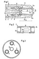
- FIG. 3 The schematic representation of Fig. 3 shows three similar burners (E), (F) and (G), each as the can be configured in Fig. 1 described burner. These burners surround a tube (18) which does not shown, releasable closure may have.
- the pipe (18) may be designed to provide one if necessary additional burner, z. B. a Auffilbrenner, but during normal operation of the Burner (E), (F) and (G) removed again.
- the number of Burner, which surround the tube (18) is arbitrary and can z. B. be two to ten.
Landscapes
- Chemical & Material Sciences (AREA)
- Engineering & Computer Science (AREA)
- Combustion & Propulsion (AREA)
- Mechanical Engineering (AREA)
- General Engineering & Computer Science (AREA)
- Chemical Kinetics & Catalysis (AREA)
- Organic Chemistry (AREA)
- Health & Medical Sciences (AREA)
- General Health & Medical Sciences (AREA)
- Inorganic Chemistry (AREA)
- Hydrogen, Water And Hydrids (AREA)
Description
- Fig. 1
- einen Längsschnitt durch den Auslaßbereich des Brenners in schematischer Darstellung,
- Fig. 2
- einen Längsschnitt durch eine Verbindungshülse und
- Fig. 3
- die Anordnung mehrerer, zusammenwirkender Brenner.
Claims (5)
- Brenner für die partielle Oxidation von flüssigem, kohlenstoffhaltigem Brennstoff mit Wasserdampf und einem sauerstoffhaltigen Gas, wobei die Austrittsmündung des Brenners in eine Brennkammer gerichtet ist, dadurch gekennzeichnet, daß der Brenner in der Nähe der Austrittsmündung eine konische, sich zur Austrittsmündung hin erweiternde Mischkammer (2) aufweist, daß ein den flüssigen Brennstoff in die Mischkammer einspeisendes erstes Rohr (1) koaxial zur Mischkammer angeordnet ist, wobei sich das Mündungsende (1a) des ersten Rohrs im Bereich des Eintrittsendes (2a) der Mischkammer befindet und zwischen dem Mündungsende des ersten Rohrs und dem Eintrittsende der Mischkammer ein Ringspalt (3) für den Durchtritt von Wasserdampf besteht, daß eine erste Ringkammer (5) für das Durchleiten von Wasserdampf das erste Rohr umgibt und mit dem Ringspalt (3) verbunden ist, daß ein zweites Rohr (6) die erste Ringkammer (5) umgibt und abgedichtet an der Außenseite der Mischkammer (2) anliegt, daß eine zweite Ringkammer (11) für das Durchleiten von sauerstoffhaltigem Gas zur Austrittsmündung des Brenners das zweite Rohr und die Mischkammer umgibt, und daß die Mischkammer von ihrer Austrittsmündung bis zur Mündung (1a) des ersten Rohrs eine axiale Länge (A) von 10 bis 300 mm, einen größten Innendurchmesser von 10 bis 100 mm und einen Konuswinkel (x), gemessen gegen die Mischkammerachse, von 3 bis 20° aufweist.
- Brenner nach Anspruch 1, dadurch gekennzeichnet, daß zwischen der Außenseite der Mischkammer (2) und der Außenseite des ersten Rohrs (1) eine Verbindungshülse (7) mit Durchtrittsöffnungen (8) angeordnet ist und daß die Hülse mindestens ein Gewinde aufweist, mit welchem sie in das erste Rohr (1) und/oder in die Wand der Mischkammer eingreift.
- Brenner nach Anspruch 2, dadurch gekennzeichnet, daß die Außenseite der Verbindungshülse (7) am zweiten Rohr (6) gleitend und abgedichtet anliegt.
- Brenner nach Anspruch 1 oder einem der folgenden, dadurch gekennzeichnet, daß sich das erste Rohr (1) zu seiner Mündung (1a) hin verengt.
- Brenner nach Anspruch 1 oder einem der folgenden, dadurch gekennzeichnet, daß mehrere Brenner parallel und in die Brennkammer gerichtet angeordnet sind, wobei sich die Brenner in unmittelbarer Nähe einer verschließbaren Öffnung in der Brennkammer befinden, in welche ein bewegbarer Brenner einsetzbar ist.
Applications Claiming Priority (2)
| Application Number | Priority Date | Filing Date | Title |
|---|---|---|---|
| DE19860479 | 1998-12-28 | ||
| DE19860479A DE19860479C1 (de) | 1998-12-28 | 1998-12-28 | Brenner für die partielle Oxidation von flüssigen, kohlenstoffhaltigen Brennstoffen |
Publications (2)
| Publication Number | Publication Date |
|---|---|
| EP1016705A1 EP1016705A1 (de) | 2000-07-05 |
| EP1016705B1 true EP1016705B1 (de) | 2004-03-24 |
Family
ID=7892965
Family Applications (1)
| Application Number | Title | Priority Date | Filing Date |
|---|---|---|---|
| EP99121717A Expired - Lifetime EP1016705B1 (de) | 1998-12-28 | 1999-11-03 | Brenner für die partielle Oxidation von flüssigen, kohlenstoffhaltigen Brennstoffen |
Country Status (6)
| Country | Link |
|---|---|
| EP (1) | EP1016705B1 (de) |
| AT (1) | ATE262572T1 (de) |
| DE (2) | DE19860479C1 (de) |
| DK (1) | DK1016705T3 (de) |
| ES (1) | ES2216412T3 (de) |
| PT (1) | PT1016705E (de) |
Cited By (2)
| Publication number | Priority date | Publication date | Assignee | Title |
|---|---|---|---|---|
| DE102011101077A1 (de) | 2011-05-10 | 2012-11-15 | L'Air Liquide, Société Anonyme pour l'Etude et l'Exploitation des Procédés Georges Claude | Verfahren und Reaktor zur autothermen Reformierung von Brennstoffen |
| EP4310394A1 (de) | 2022-07-21 | 2024-01-24 | L'air Liquide, Société Anonyme Pour L'Étude Et L'exploitation Des Procédés Georges Claude | Brenneranordnung für die synthesegaserzeugung |
Families Citing this family (3)
| Publication number | Priority date | Publication date | Assignee | Title |
|---|---|---|---|---|
| DE10156980B4 (de) * | 2001-11-21 | 2004-08-05 | Lurgi Ag | Verfahren zur Herstellung von Synthesegas |
| DE10357474B4 (de) * | 2003-12-09 | 2006-05-24 | Webasto Ag | System zum Umsetzen von Brennstoff und Luft zu Reformat |
| DE102010033935B4 (de) | 2010-08-10 | 2013-01-17 | Lurgi Gmbh | Brenner und Verfahren für die partielle Oxidation von flüssigem, kohlenstoffhaltigem Brennstoff |
Family Cites Families (12)
| Publication number | Priority date | Publication date | Assignee | Title |
|---|---|---|---|---|
| USRE24771E (en) * | 1960-01-19 | Vaporizing and mixing unit | ||
| US1655810A (en) * | 1924-04-24 | 1928-01-10 | David J Cartwright | Fuel atomizing and vaporizing apparatus |
| US1999121A (en) * | 1934-03-26 | 1935-04-23 | Robert J Wilson | Oil burner |
| JPS5028657B1 (de) * | 1969-10-21 | 1975-09-17 | ||
| NL7515165A (nl) * | 1975-12-30 | 1977-07-04 | Shell Int Research | Werkwijze en brander voor de partiele verbranding van een vloeibare of gasvormige brandstof, als- mede werkwijze voor de reductie van zwavelverbin- dingen bevattende afgassen. |
| US4341530A (en) * | 1979-12-05 | 1982-07-27 | The United States Of America As Represented By The Department Of Energy | Slurry atomizer for a coal-feeder and dryer used to provide coal at gasifier pressure |
| US4493636A (en) * | 1981-03-05 | 1985-01-15 | The United States Of America As Represented By The United States Department Of Energy | Gasification system |
| US4443230A (en) * | 1983-05-31 | 1984-04-17 | Texaco Inc. | Partial oxidation process for slurries of solid fuel |
| DE3735002A1 (de) * | 1987-10-16 | 1989-04-27 | Metallgesellschaft Ag | Verfahren zum entfernen von schwefelwasserstoff aus abgas |
| DE3902773A1 (de) * | 1989-01-31 | 1990-08-02 | Basf Ag | Verfahren zur herstellung von synthesegas durch partielle oxidation |
| DE4437628C2 (de) * | 1994-10-21 | 1997-09-18 | Metallgesellschaft Ag | Verfahren zum Reinigen eines Gases mit einer Waschflüssigkeit |
| US5772708A (en) * | 1995-03-17 | 1998-06-30 | Foster Wheeler Development Corp. | Coaxial coal water paste feed system for gasification reactor |
-
1998
- 1998-12-28 DE DE19860479A patent/DE19860479C1/de not_active Expired - Fee Related
-
1999
- 1999-11-03 AT AT99121717T patent/ATE262572T1/de active
- 1999-11-03 DK DK99121717T patent/DK1016705T3/da active
- 1999-11-03 DE DE59908947T patent/DE59908947D1/de not_active Expired - Lifetime
- 1999-11-03 EP EP99121717A patent/EP1016705B1/de not_active Expired - Lifetime
- 1999-11-03 ES ES99121717T patent/ES2216412T3/es not_active Expired - Lifetime
- 1999-11-03 PT PT99121717T patent/PT1016705E/pt unknown
Cited By (3)
| Publication number | Priority date | Publication date | Assignee | Title |
|---|---|---|---|---|
| DE102011101077A1 (de) | 2011-05-10 | 2012-11-15 | L'Air Liquide, Société Anonyme pour l'Etude et l'Exploitation des Procédés Georges Claude | Verfahren und Reaktor zur autothermen Reformierung von Brennstoffen |
| WO2012152772A1 (en) | 2011-05-10 | 2012-11-15 | Lurgi Gmbh | Process and reactor for producing synthesis gas |
| EP4310394A1 (de) | 2022-07-21 | 2024-01-24 | L'air Liquide, Société Anonyme Pour L'Étude Et L'exploitation Des Procédés Georges Claude | Brenneranordnung für die synthesegaserzeugung |
Also Published As
| Publication number | Publication date |
|---|---|
| DE19860479C1 (de) | 2000-08-03 |
| EP1016705A1 (de) | 2000-07-05 |
| DK1016705T3 (da) | 2004-06-21 |
| ATE262572T1 (de) | 2004-04-15 |
| ES2216412T3 (es) | 2004-10-16 |
| DE59908947D1 (de) | 2004-04-29 |
| PT1016705E (pt) | 2004-07-30 |
Similar Documents
| Publication | Publication Date | Title |
|---|---|---|
| EP0095103B1 (de) | Verfahren und Vorrichtung zur Herstellung von Synthesegas durch partielle Oxidation von Kohle-Wasser-Suspensionen | |
| DE69510395T3 (de) | Gasbrenner für Industrieöfen | |
| DE2539888C2 (de) | Verfahren zur Vergasung von fein dispergierte Feststoffe enthaltendem Öl durch partielle Oxydation unter Flammenbildung und Einrichtung zu seiner Durchführung | |
| DE3933050C2 (de) | Verfahren zum Betreiben eines Brenners für Drehrohröfen und Brenner hierfür | |
| DE3327597A1 (de) | Verfahren und brenner zum verbrennen von fluessigen oder gasfoermigen brennstoffen unter verminderter bildung von nox | |
| EP0907868B1 (de) | Brenner | |
| DE1906895B2 (de) | Vorrichtung zur direkten Beheizung eines Wirbelschichtreaktors | |
| EP1016705B1 (de) | Brenner für die partielle Oxidation von flüssigen, kohlenstoffhaltigen Brennstoffen | |
| DE3441358C2 (de) | Verfahren und Vorrichtung zur Verbrennung und Vergasung von pulverförmigem kohlenstoffhaltigen Material | |
| EP0386732A2 (de) | Verbrennungseinrichtung für einen Zweistoffbrenner | |
| DE102007021925B4 (de) | Kompakt-Kohlenstaubbrenner | |
| EP1200338B1 (de) | Brenner für die partielle oxidation von flüssigen, kohlenstoffhaltigen brennstoffen | |
| DE2430433C2 (de) | Zerstäuber | |
| DE3808729A1 (de) | Verfahren und vorrichtung zur abkuehlung des aus einem vergasungsreaktor austretenden heissen produktgases | |
| DE102004059679B4 (de) | Rundbrenner zur Verbrennung von staubförmigem Brennstoff | |
| DE2226621C3 (de) | Zerstäubungsbrenner | |
| DD151019A3 (de) | Kohlenstaubbrenner | |
| DE2537948C2 (de) | Vorrichtung zur Vergasung von Kohlenstoff enthaltenden Brennstoffstaub | |
| DE68905681T2 (de) | Methode zur umaenderung der schmutzstoffe in einem rohen hochtemperatur-hochdruck-synthesegasstrom. | |
| EP0011904B1 (de) | Drallbrenner für Kohlevergasungsreaktoren | |
| DE1645865C2 (de) | Verfahren zur Herstellung eines Kohlenmonoxid und Wasserstoff als wesentliche Bestandteile enthaltenden Produktgasgemisches | |
| DE1501981A1 (de) | Kombinationsbrenner | |
| EP0172303A1 (de) | Brenner für flüssige, insbesondere feste Anteile enthaltende Brennstoffe | |
| DE2843883C3 (de) | Verfahren zur Erzeugung von schwefelarmem Koksstaub und Gas durch Ent- und Teilvergasung von Kohlenstaub in einer Reaktionskammer | |
| AT220275B (de) | Verfahren und Vorrichtung zum Mischen gasförmiger Medien sowie Brenner mit derartiger Mischvorrichtung |
Legal Events
| Date | Code | Title | Description |
|---|---|---|---|
| PUAI | Public reference made under article 153(3) epc to a published international application that has entered the european phase |
Free format text: ORIGINAL CODE: 0009012 |
|
| AK | Designated contracting states |
Kind code of ref document: A1 Designated state(s): AT BE CH CY DE DK ES FI FR GB GR IE IT LI LU MC NL PT SE |
|
| AX | Request for extension of the european patent |
Free format text: AL;LT;LV;MK;RO;SI |
|
| RIN1 | Information on inventor provided before grant (corrected) |
Inventor name: WEBER, ROLAND Inventor name: GRUENFELDER, GERD JOHANN Inventor name: FELLNER, HELMUT Inventor name: LIEBNER, WALDEMAR, DR. Inventor name: QUASS, GUNTER Inventor name: BREHM, LOTHAR Inventor name: ZWIEFELHOFER, UWE |
|
| 17P | Request for examination filed |
Effective date: 20010105 |
|
| AKX | Designation fees paid |
Free format text: AT BE CH CY DE DK ES FI FR GB GR IE IT LI LU MC NL PT SE |
|
| RAP1 | Party data changed (applicant data changed or rights of an application transferred) |
Owner name: MG TECHNOLOGIES AG |
|
| GRAP | Despatch of communication of intention to grant a patent |
Free format text: ORIGINAL CODE: EPIDOSNIGR1 |
|
| GRAS | Grant fee paid |
Free format text: ORIGINAL CODE: EPIDOSNIGR3 |
|
| GRAA | (expected) grant |
Free format text: ORIGINAL CODE: 0009210 |
|
| AK | Designated contracting states |
Kind code of ref document: B1 Designated state(s): AT BE CH CY DE DK ES FI FR GB GR IE IT LI LU MC NL PT SE |
|
| PG25 | Lapsed in a contracting state [announced via postgrant information from national office to epo] |
Ref country code: IE Free format text: LAPSE BECAUSE OF FAILURE TO SUBMIT A TRANSLATION OF THE DESCRIPTION OR TO PAY THE FEE WITHIN THE PRESCRIBED TIME-LIMIT Effective date: 20040324 Ref country code: CY Free format text: LAPSE BECAUSE OF FAILURE TO SUBMIT A TRANSLATION OF THE DESCRIPTION OR TO PAY THE FEE WITHIN THE PRESCRIBED TIME-LIMIT Effective date: 20040324 |
|
| REG | Reference to a national code |
Ref country code: GB Ref legal event code: FG4D Free format text: NOT ENGLISH |
|
| REG | Reference to a national code |
Ref country code: CH Ref legal event code: EP |
|
| REG | Reference to a national code |
Ref country code: SE Ref legal event code: TRGR |
|
| REG | Reference to a national code |
Ref country code: IE Ref legal event code: FG4D Free format text: GERMAN |
|
| REF | Corresponds to: |
Ref document number: 59908947 Country of ref document: DE Date of ref document: 20040429 Kind code of ref document: P |
|
| REG | Reference to a national code |
Ref country code: GR Ref legal event code: EP Ref document number: 20040401253 Country of ref document: GR |
|
| REG | Reference to a national code |
Ref country code: DK Ref legal event code: T3 |
|
| REG | Reference to a national code |
Ref country code: PT Ref legal event code: SC4A Free format text: AVAILABILITY OF NATIONAL TRANSLATION Effective date: 20040514 |
|
| GBT | Gb: translation of ep patent filed (gb section 77(6)(a)/1977) |
Effective date: 20040712 |
|
| REG | Reference to a national code |
Ref country code: ES Ref legal event code: FG2A Ref document number: 2216412 Country of ref document: ES Kind code of ref document: T3 |
|
| REG | Reference to a national code |
Ref country code: IE Ref legal event code: FD4D |
|
| ET | Fr: translation filed | ||
| PG25 | Lapsed in a contracting state [announced via postgrant information from national office to epo] |
Ref country code: MC Free format text: LAPSE BECAUSE OF NON-PAYMENT OF DUE FEES Effective date: 20041130 Ref country code: LI Free format text: LAPSE BECAUSE OF NON-PAYMENT OF DUE FEES Effective date: 20041130 Ref country code: CH Free format text: LAPSE BECAUSE OF NON-PAYMENT OF DUE FEES Effective date: 20041130 |
|
| PLBE | No opposition filed within time limit |
Free format text: ORIGINAL CODE: 0009261 |
|
| STAA | Information on the status of an ep patent application or granted ep patent |
Free format text: STATUS: NO OPPOSITION FILED WITHIN TIME LIMIT |
|
| 26N | No opposition filed |
Effective date: 20041228 |
|
| REG | Reference to a national code |
Ref country code: CH Ref legal event code: PL |
|
| REG | Reference to a national code |
Ref country code: FR Ref legal event code: PLFP Year of fee payment: 17 |
|
| PGFP | Annual fee paid to national office [announced via postgrant information from national office to epo] |
Ref country code: FI Payment date: 20151111 Year of fee payment: 17 Ref country code: DK Payment date: 20151118 Year of fee payment: 17 Ref country code: LU Payment date: 20151119 Year of fee payment: 17 Ref country code: GR Payment date: 20151112 Year of fee payment: 17 |
|
| PGFP | Annual fee paid to national office [announced via postgrant information from national office to epo] |
Ref country code: BE Payment date: 20151118 Year of fee payment: 17 Ref country code: AT Payment date: 20151119 Year of fee payment: 17 Ref country code: ES Payment date: 20151111 Year of fee payment: 17 Ref country code: PT Payment date: 20151102 Year of fee payment: 17 Ref country code: SE Payment date: 20151118 Year of fee payment: 17 |
|
| REG | Reference to a national code |
Ref country code: FR Ref legal event code: PLFP Year of fee payment: 18 |
|
| PG25 | Lapsed in a contracting state [announced via postgrant information from national office to epo] |
Ref country code: BE Free format text: LAPSE BECAUSE OF NON-PAYMENT OF DUE FEES Effective date: 20161130 |
|
| REG | Reference to a national code |
Ref country code: DK Ref legal event code: EBP Effective date: 20161130 |
|
| REG | Reference to a national code |
Ref country code: SE Ref legal event code: EUG |
|
| REG | Reference to a national code |
Ref country code: AT Ref legal event code: MM01 Ref document number: 262572 Country of ref document: AT Kind code of ref document: T Effective date: 20161103 |
|
| PG25 | Lapsed in a contracting state [announced via postgrant information from national office to epo] |
Ref country code: FI Free format text: LAPSE BECAUSE OF NON-PAYMENT OF DUE FEES Effective date: 20161103 Ref country code: GR Free format text: LAPSE BECAUSE OF NON-PAYMENT OF DUE FEES Effective date: 20170612 |
|
| PG25 | Lapsed in a contracting state [announced via postgrant information from national office to epo] |
Ref country code: SE Free format text: LAPSE BECAUSE OF NON-PAYMENT OF DUE FEES Effective date: 20161104 Ref country code: AT Free format text: LAPSE BECAUSE OF NON-PAYMENT OF DUE FEES Effective date: 20161103 Ref country code: PT Free format text: LAPSE BECAUSE OF NON-PAYMENT OF DUE FEES Effective date: 20170503 |
|
| PG25 | Lapsed in a contracting state [announced via postgrant information from national office to epo] |
Ref country code: LU Free format text: LAPSE BECAUSE OF NON-PAYMENT OF DUE FEES Effective date: 20161130 |
|
| REG | Reference to a national code |
Ref country code: FR Ref legal event code: PLFP Year of fee payment: 19 |
|
| PG25 | Lapsed in a contracting state [announced via postgrant information from national office to epo] |
Ref country code: DK Free format text: LAPSE BECAUSE OF NON-PAYMENT OF DUE FEES Effective date: 20161130 |
|
| REG | Reference to a national code |
Ref country code: BE Ref legal event code: MM Effective date: 20161130 |
|
| PG25 | Lapsed in a contracting state [announced via postgrant information from national office to epo] |
Ref country code: ES Free format text: LAPSE BECAUSE OF FAILURE TO SUBMIT A TRANSLATION OF THE DESCRIPTION OR TO PAY THE FEE WITHIN THE PRESCRIBED TIME-LIMIT Effective date: 20040324 |
|
| REG | Reference to a national code |
Ref country code: ES Ref legal event code: FD2A Effective date: 20181116 |
|
| PGFP | Annual fee paid to national office [announced via postgrant information from national office to epo] |
Ref country code: NL Payment date: 20181120 Year of fee payment: 20 |
|
| PGFP | Annual fee paid to national office [announced via postgrant information from national office to epo] |
Ref country code: DE Payment date: 20181120 Year of fee payment: 20 |
|
| RIC2 | Information provided on ipc code assigned after grant |
Ipc: C01B 3/36 20060101ALI20000316BHEP Ipc: F23D 11/10 20060101ALI20000316BHEP Ipc: C10J 3/50 20060101AFI20000316BHEP Ipc: F23D 23/00 20060101ALI20000316BHEP |
|
| PG25 | Lapsed in a contracting state [announced via postgrant information from national office to epo] |
Ref country code: ES Free format text: LAPSE BECAUSE OF FAILURE TO SUBMIT A TRANSLATION OF THE DESCRIPTION OR TO PAY THE FEE WITHIN THE PRESCRIBED TIME-LIMIT Effective date: 20161104 |
|
| PGFP | Annual fee paid to national office [announced via postgrant information from national office to epo] |
Ref country code: IT Payment date: 20181126 Year of fee payment: 20 Ref country code: GB Payment date: 20181120 Year of fee payment: 20 Ref country code: FR Payment date: 20181123 Year of fee payment: 20 |
|
| REG | Reference to a national code |
Ref country code: DE Ref legal event code: R071 Ref document number: 59908947 Country of ref document: DE |
|
| REG | Reference to a national code |
Ref country code: NL Ref legal event code: MK Effective date: 20191102 |
|
| REG | Reference to a national code |
Ref country code: GB Ref legal event code: PE20 Expiry date: 20191102 |
|
| PG25 | Lapsed in a contracting state [announced via postgrant information from national office to epo] |
Ref country code: GB Free format text: LAPSE BECAUSE OF EXPIRATION OF PROTECTION Effective date: 20191102 |