EP1014385B1 - Strahlpumpenhilfskeil - Google Patents
Strahlpumpenhilfskeil Download PDFInfo
- Publication number
- EP1014385B1 EP1014385B1 EP99310363A EP99310363A EP1014385B1 EP 1014385 B1 EP1014385 B1 EP 1014385B1 EP 99310363 A EP99310363 A EP 99310363A EP 99310363 A EP99310363 A EP 99310363A EP 1014385 B1 EP1014385 B1 EP 1014385B1
- Authority
- EP
- European Patent Office
- Prior art keywords
- wedge
- support block
- channel
- restrainer bracket
- engage
- Prior art date
- Legal status (The legal status is an assumption and is not a legal conclusion. Google has not performed a legal analysis and makes no representation as to the accuracy of the status listed.)
- Expired - Lifetime
Links
Images


Classifications
-
- G—PHYSICS
- G21—NUCLEAR PHYSICS; NUCLEAR ENGINEERING
- G21C—NUCLEAR REACTORS
- G21C15/00—Cooling arrangements within the pressure vessel containing the core; Selection of specific coolants
- G21C15/24—Promoting flow of the coolant
- G21C15/243—Promoting flow of the coolant for liquids
- G21C15/25—Promoting flow of the coolant for liquids using jet pumps
-
- Y—GENERAL TAGGING OF NEW TECHNOLOGICAL DEVELOPMENTS; GENERAL TAGGING OF CROSS-SECTIONAL TECHNOLOGIES SPANNING OVER SEVERAL SECTIONS OF THE IPC; TECHNICAL SUBJECTS COVERED BY FORMER USPC CROSS-REFERENCE ART COLLECTIONS [XRACs] AND DIGESTS
- Y02—TECHNOLOGIES OR APPLICATIONS FOR MITIGATION OR ADAPTATION AGAINST CLIMATE CHANGE
- Y02E—REDUCTION OF GREENHOUSE GAS [GHG] EMISSIONS, RELATED TO ENERGY GENERATION, TRANSMISSION OR DISTRIBUTION
- Y02E30/00—Energy generation of nuclear origin
- Y02E30/30—Nuclear fission reactors
Definitions
- This invention relates generally to nuclear reactors and more particularly, to apparatus for repairing jet pump assemblies within a nuclear reactor pressure vessel.
- a reactor pressure vessel (RPV) of a boiling water reactor (BWR) typically has a generally cylindrical shape and is closed at both ends, e.g., by a bottom head and a removable top head.
- a top guide typically is spaced above a core plate within the RPV.
- a core shroud, or shroud typically surrounds the core and is supported by a shroud support structure. Particularly, the shroud has a generally cylindrical shape and surrounds both the core plate and the top guide. There is a space or annulus located between the cylindrical reactor pressure vessel and the cylindrically shaped shroud.
- hollow tubular jet pumps positioned within the shroud annulus, provide the required reactor core water flow.
- the upper portion of the jet pump known as the inlet mixer, is laterally positioned and supported against two opposing rigid contacts within restrainer brackets by a gravity actuated wedge.
- the restrainer brackets support the inlet mixer by attaching to the adjacent jet pump riser pipe.
- the purpose of the gravity actuated wedge is to maintain contact between the inlet mixer and the restrainer bracket.
- the wedge works in cooperation with two set screws which are tack welded to the restrainer bracket to maintain contact with the inlet mixer.
- the flow of water through the jet pumps typically includes pressure fluctuations which are caused by various sources in the reactor system.
- the pressure fluctuations may have frequencies close to one or more natural vibration modes of the jet pump piping.
- the jet pump piping stability depends on the tight fit-up, or contact, of the restrainer brackets and the inlet mixers. Operating thermal gradients, hydraulic loads, and fluctuations in the hydraulic loads can overcome the lateral support provided by the gravity wedge, allowing gaps or clearances to develop at the opposing two fixed contacts or set screws. Particularly, the tack welds can break and the set screws can loosen permitting the jet pump to vibrate within the restrainer bracket.
- the loss of contact between the inlet mixer and the restrainer bracket can change the jet pump natural frequency to match some excitation frequency in the system, causing vibration of the piping and exerting increased loads which may cause cyclic fatigue cracking and wear of the piping supports, which can result in degradation from wear and fatigue at additional jet pump structural supports.
- gravity wedge supports have been used at locations where clearances have developed in restrainer bracket contacts.
- the gravity wedge support employed a sliding wedge and a fixed bracket mount which engaged the jet pump restrainer bracket.
- To allow access for installation of the wedge support required disassembly of the jet pumps, which is an undesirable expense and may cause an extension of reactor maintenance downtime.
- the gravity wedge supports typically included bolted attachments which could vibrate loose and fall into the reactor.
- Another attempted solution is to reinforce the welded attachment of the two set screws to the restrainer bracket, then reset the inlet mixer against the set screws when the jet pump is reassembled. However, this procedure causes significant downtime and also requires disassembling the jet pumps.
- auxiliary wedge apparatus configured to couple to the restrainer bracket at a position adjacent an existing screw type contact, typically a setscrew.
- the auxiliary wedge apparatus includes a support bracket configured to couple to the restrainer bracket, and a wedge configured to slidingly couple to a wedge channel in the support block. The wedge is also configured, to engage the inlet mixer to restore a tight rigid fit-up of the jet pump components.
- the support block includes a first portion and a second portion.
- the first portion includes a wedge channel tapering from the top of the first portion.
- a hook shaped section is located at a bottom end of the first portion. The hooked shaped section is configured to receive the restrainer bracket.
- the second portion of the support block extends from the top end of the first portion away from the wedge channel.
- a screw opening extends through the second portion of the support block.
- a lock screw is configured to threadingly engage and, extend through the screw opening.
- the head of the lock screw includes a plurality of ratchet teeth located around the periphery of the head.
- a double cantilever spring is coupled to the top of the support block and is configured to engage the ratchet teeth of the lock screw. The engagement of the spring with the ratchet teeth prevents the lock screw from loosening.
- the second portion also includes a release opening located adjacent the double cantilever spring and configured to receive a release tool to enable the lock screw to be loosened.
- the support block also includes a restraint arm depending from the second portion.
- the restraint arm is configured to capture the existing setscrew located in the restrainer bracket. The restraint arm prevents the set screw from completely unscrewing and falling into the reactor.
- the wedge channel extends longitudinally in the first portion of the support block, and is tapered from the top to the bottom of the support block.
- Each opposing parallel side of the wedge channel includes a tongue extending longitudinally and configured to be parallel to the tapered bottom of the wedge channel.
- the wedge includes a groove located in each of the opposing parallel sides of the wedge.
- the grooves are configured to slidingly engage the respective tongues located in the opposing sides of the wedge channel.
- the wedge also includes a stop screw to prevent the wedge from passing completely through the wedge channel.
- the stop screw is configured to threadingly engage a screw opening in the tapered side at the top of the wedge.
- the wedge includes an integral installation handling opening extending through the top of the wedge.
- the auxiliary wedge apparatus is coupled to the restrainer bracket.
- the auxiliary wedge apparatus is preassembled. Particularly, the wedge is inserted into the wedge channel of the support block with the tongues on the sides of the wedge channel engaging the grooves of the wedge. The thick end of the wedge is inserted into the bottom of the wedge channel and the wedge is then slid up the channel. The grooves in the wedge are configured so that the wedge cannot slide completely up through the channel.
- the stop screw is threaded into the screw opening at the top of the wedge and locked by a pin captured in a drilled hole. The stop screw prevents the wedge from disengaging by sliding all the way back down the wedge channel.
- the auxiliary wedge apparatus is then lowered onto the restrainer bracket by the handling opening in the top of the wedge.
- the apparatus is configured to fit between the inlet mixer and the restrainer bracket without disassembly of the inlet mixer.
- the hooked shaped portion of the support block is forced into engagement with the restrainer bracket.
- the lock screw is then screwed into the lock screw opening in the support block.
- the action of the lock screw and the hook shaped portion of the support block couple the apparatus to the restrainer bracket.
- the ratchet teeth on the head of the lock screw engage the double cantilever spring which prevents the lock screw from loosening.
- the wedge is then released from the handling pole and gravity causes the wedge to slide down the wedge channel into tight contact with the inlet mixer.
- the wedging action of the wedge between the inlet mixer and the support block which is coupled to the restrainer bracket provides a tight fit-up of the inlet mixer.
- a release tool is inserted into the lock screw release opening.
- the release tool is configured to engage and deflect the double cantilever spring, which releases the engagement between the spring and the ratchet teeth of the lock screw.
- the lock screw is then loosened until it clears the bracket, permitting the apparatus to be decoupled from the restrainer bracket and removed from the reactor.
- the above described auxiliary wedge apparatus restores the tight rigid fit-up between the inlet mixer and the adjacent restrainer bracket, replacing the support function of the existing screw type contacts.
- the apparatus includes a restraint arm to prevent the existing set screws from backing out completely and escaping into the reactor system. Additionally, the apparatus may be remotely installed by attachment to the existing restrainer bracket, and is configured to remain in place during disassembly of the jet pumps during maintenance shutdowns. Further the auxiliary wedge apparatus, when assembled, does not contain parts that are susceptible to loosening during reactor operation and falling into the reactor.
- Figure 1 is a side view of a boiling water nuclear reactor jet pump assembly.
- Figure 2 is a cross sectional view through line B-B of the jet pump assembly shown in Figure 1.
- Figure 3 is a top sectional view of an auxiliary wedge apparatus in accordance with one embodiment of the present invention.
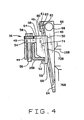
- Figure 4 is a side view of the auxiliary wedge apparatus shown in Figure 3.
- FIG. 1 is a side view of a boiling water nuclear reactor jet pump assembly 10. Water flows through jet pump assembly 10 and into the reactor core (not shown). Jet pump assembly 10 includes a riser assembly 12, a transition assembly 14, two inlet mixer assemblies 16A and 16B, and two diffuser assemblies 18A and 18B. Particularly, riser assembly 12 is supported by riser braces 20A and 20B which couple riser 12 to the reactor vessel (not shown). Transition assembly 14 is coupled to the upper end 22 of riser 12 to split the flow of water into two paths, one through inlet mixer 16A and the other through inlet mixer 16B. Water enters riser assembly 12 through jet pump inlet nozzle 24.
- Inlet mixers 16A and 16B are coupled at one end to transition piece 14 by elbows 26A and 26B respectively, and at an opposite end to jet pump diffuser assemblies 18A and 18B respectively.
- restrainer brackets 28A and 28B couple inlet mixer assemblies 16A and 16B to riser pipe 12.
- wedges 30A and 30B are positioned between restrainer brackets 28A and 28B and inlet mixers 16A and 16B respectively.
- Screw contacts 32A, 32B, 32C, and 32D extend through restrainer brackets 28A and 28B and contact mixers 16A and 16B respectively to provide a tight rigid fit-up.
- Screw contacts 32A and 32B are each located 120 away from wedge 30A in restrainer bracket 28A
- screw contacts 32C and 32D are each located 120 away from wedge 30B in restrainer bracket 28B.
- set screws 32A, 32B, 32C, and 32 D are tack welded to restrainer brackets 28A and 28B to prevent set screws 32A, 32B, 32C, and 32D from loosening.
- FIG 3 is a top view of an auxiliary wedge apparatus 36, coupled to inlet mixer 16B
- Figure 4 is a side view of auxiliary wedge apparatus 36.
- auxiliary wedge apparatus 36 is configured to couple to restrainer bracket 28B at a position adjacent to set screw 32C.
- auxiliary wedge apparatus 36 may be configured to couple to restrainer bracket 28A or 28B at a position adjacent to one of set screws 32A, 32B, 32C or 32D.
- Auxiliary wedge apparatus 36 includes a support block 38 configured to couple to restrainer bracket 28B, and a wedge 40 configured to slidably couple to a wedge channel 42 located in support block 38.
- Wedge 40 is also configured to engage inlet mixer 16B to restore a tight rigid fit-up of inlet mixer 16B with restrainer bracket 28B in the event that set screw 32C loosens.
- Auxiliary wedge apparatus 36 also includes a restrainer arm 44 configured to engage loose set screw 32C and prevent set screw 32C from backing out from restrainer bracket 28B and falling into the reactor.
- support block 38 includes a first portion 46 and a second portion 48.
- First portion 46 includes wedge channel 42 tapering from the top 50 of first portion 46.
- a hook shaped section 52 is located at a bottom end 55 of first portion 46. Hooked shaped section 52 is configured to receive restrainer bracket 28B.
- Second portion 48 extends from top end 50 of first portion 46 away from wedge channel 42.
- a screw opening 54 extends through second portion 48 of support block 38.
- a lock screw 56 is configured to threadingly engage and extend through screw opening 54.
- the head 58 of lock screw 56 includes a plurality of ratchet teeth 60 located around the periphery of head 58.
- a double cantilever spring 62 is coupled to the top 64 of support block 38 and is configured to engage ratchet teeth 60 of lock screw 58. The engagement of spring 62 with ratchet teeth 60 prevents lock screw 56 from loosening.
- Second portion 48 also includes a release opening 66 located adjacent double cantilever spring 62 and configured to receive a release tool (not shown) to enable lock screw 56 to be loosened.
- Support block 38 also includes restraint arm 44 depending from second portion 48. Restraint arm 44 is configured to capture existing set screw 32C located in restrainer bracket 16B. Restraint arm 44 prevents set screw 23C from completely unscrewing and falling into the reactor.
- Wedge channel 42 extends longitudinally in first portion 46 of support block 38, and is tapered from top 64 to bottom 68 of support block 38.
- Opposing parallel sides 70A and 70B of wedge channel 42 includes tongues 72A and 72B respectively.
- Tongues 72A and 72B extend longitudinally and are configured to be parallel to a tapered bottom 74 of wedge channel 42.
- Wedge 40 includes grooves 76A and 76B located in opposing parallel sides 78A and 78B respectively. Grooves 76A and 76B are configured to slidingly engage tongues 72A and 72B respectively. Wedge 40 also includes a stop screw 80 to prevent wedge 40 from disengaging wedge channel 42 by passing completely through wedge channel 42. Particularly, stop screw 80 is configured to threadingly engage a screw opening 82 in a tapered side 84 of wedge 40 located at top 86 of wedge 40. Stop screw 80 is locked in place by a pin 81 captured in a locking pin hole 83. Additionally, a handling opening 88 extends through top 86 of wedge 40.
- Auxiliary wedge apparatus 36 may be fabricated from any suitable material, For example, austenitic stainless steel with a nitride hardened surface, or age hardened nickel-chrome-iron alloy X-750 may be used.
- double cantilever spring 62 is fabricated from age hardened nickel-chrome-iron alloy X-750.
- auxiliary wedge apparatus 36 is coupled to restrainer bracket 28B.
- wedge 40 is inserted into wedge channel 42 of support block 38 with the tongues 72A and 72B of wedge channel 42 engaging grooves 76A and 76B of wedge 40 respectively.
- Top end 84, which is the thick end, of wedge 40 is inserted into the bottom of wedge channel 42 and wedge 40 is then slid up channel 42.
- Grooves 76A and 76B in wedge 40 are configured so that wedge 40 cannot slide completely up through channel 42.
- stop screw 80 is threaded into screw opening 82 at top 84 of wedge 40 and locked by pin 81 captured in locking pin hole 83. Stop screw 80 prevents wedge 40 from disengaging by sliding all the way back down wedge channel 42.
- Auxiliary wedge apparatus 36 is then lowered onto restrainer bracket 28B with the use of handling opening 88 in top 84 of wedge 40.
- Apparatus 36 is configured to fit between inlet mixer 16B and restrainer bracket 28B.
- hooked shaped section 52 of support block 38 is forced into engagement with restrainer bracket 28B.
- Lock screw 56 is then screwed into the lock screw opening 54 in support block 38.
- Ratchet teeth 60 located on head 58 of lock screw 56 engages double cantilever spring 62 which prevents lock screw 56 from loosening.
- Wedge 40 is then released from the handling pole (not shown) and gravity causes wedge 40 to slide down wedge channel 42 into contact with inlet mixer 16B.
- the wedging action of wedge 40 between inlet mixer 16B and support block 38 which is coupled to restrainer bracket 28B provides a tight fit-up of inlet mixer 16B.
- a release tool (not shown) is inserted into release opening 66.
- the release tool is configured to engage double cantilever spring 62 which releases the engagement between spring 62 and ratchet teeth 60 of lock screw 56. Lock screw 56 is then loosened and removed, permitting apparatus 36 to be decoupled from restrainer bracket 28B and removed from the reactor.
- auxiliary wedge apparatus 36 restores the tight rigid fit-up between inlet mixers 16A and 16B and adjacent restrainer bracket 28A and 28B, replacing the support function of existing screw type contacts 32A, 32B, 32C, and 32D.
- apparatus 36 includes restraint arm 44 to prevent existing set screws 32A , 32B, 32C, and 32D from backing out completely and escaping into the reactor system.
- apparatus 36 may be remotely installed by attachment to existing restrainer bracket 28A and 28B, and is configured to stay in place during disassembly of the jet pump assembly 10 during maintenance shutdowns. Further auxiliary wedge apparatus 36, when assembled, does not contain parts that are susceptible to loosening during reactor operation and falling into the reactor.
Claims (15)
- Hilfskeilvorrichtung (36) zum Wiederherstellen des dichten starren Sitzes zwischen einer Einlassmischdüse (16B) einer Strahlpumpe (10) und einer benachbarten Rückhalteklammer (28B), die mit einem Strahlpumpensteigrohr (12) in einem Siedewasserreaktordruckgefäß verbunden ist, wobei zu dem Druckgefäß eine Strahlpumpe (10) und ein Strahlpumpensteigrohr (12) gehören, wobei die Vorrichtung (36) aufweist:einen Trägerblock (38), der dazu eingerichtet ist, benachbart der Einlassmischdüse (16B) mit der Rückhalteklammer (28B) in Eingriff zu kommen, und der einen flach abgewinkelten Keilkanal (42) aufweist; undeinen Keil (40), der dazu eingerichtet ist, gleitend mit dem Keilkanal (42) des Trägerblocks (38) in Eingriff zu kommen, wobei der Keil (40) sich von einem ersten Ende aus hin zu einem zweiten Ende verjüngt.
- Vorrichtung (36) nach Anspruch 1, wobei zu dem Keilkanal (42) gehören: eine erste Seite (70A), eine zweite Seite (70B) und ein Boden (74), der sich von einem ersten Ende (64) des Trägerblocks (38) ausgehend verjüngt.
- Vorrichtung (36) nach Anspruch 2, wobei der Keilkanal (42) ferner umfasst: eine erste Zunge (72A), die sich von der ersten Seite (70A) aus erstreckt, und eine zweite Zunge (72B), die sich von der zweiten Seite (70B) aus erstreckt, wobei sich die erste und die zweite Zunge (72A, 72B) in Längsrichtung erstrecken und dazu eingerichtet sind, um gegenüber dem Boden (74) des Keilkanals (42) parallel zu verlaufen.
- Vorrichtung (36) nach Anspruch 3, wobei der Keil (40) eine erste Nut (76A), die in einer ersten Seite (78A) des Keils (40) angeordnet ist, und eine zweite Nut (76B) aufweist, die in einer zweiten Seite (78B) des Keils (40) angeordnet ist, wobei die erste und zweite Seite (78A, 78B) konfiguriert sind, um im Wesentlichen parallel zu verlaufen, wobei die erste und die zweite Nut (76A, 76B) dazu eingerichtet sind, die erste bzw. die zweite Zunge (72A, 72B) gleitend in Eingriff zu nehmen.
- Vorrichtung (36) nach Anspruch 4, wobei der Keil (40) ferner eine Anschlagschraube (80) umfasst, die an einer sich verjüngende Seite (84) des Keils (40) angebracht und an dem ersten Ende (86) des Keils (40) angeordnet ist.
- Vorrichtung (36) nach einem beliebigen der vorhergehenden Ansprüche, bei der der Trägerblock (38) einen ersten Abschnitt (46) und einen zweiten Abschnitt (48) aufweist, wobei der erste Abschnitt (46) ein erstes Ende (50) und ein zweites Ende (55) hat, und den sich von dem ersten Ende (50) aus verjüngenden Keilkanal (42) und einen hakenförmigen Querschnitt (52) aufweist, der an dem zweiten Ende (55) angeordnet ist und dazu eingerichtet ist, die Rückhalteklammer (28B) aufzunehmen, wobei sich der zweite Abschnitt (48) des Trägerblocks (38) von dem ersten Ende (50) des ersten Abschnitts (46) aus von dem Keilkanal (42) weg erstreckt.
- Vorrichtung (36) nach Anspruch 6, wobei der zweite Abschnitt (48) ferner eine sich durch ihn hindurch erstreckende Schraubenöffnung (54) und eine Klemmschraube (56) umfasst, die dazu eingerichtet ist, mit der Schraubenöffnung (54) in Gewindeeingriff zu kommen und sich durch diese hindurch zu erstrecken, wobei die Klemmschraube (56) einen Schraubenkopf (58) und mehrere um den Umfang des Schraubenkopfs (58) herum angeordnete Rastzähne (60) aufweist.
- Vorrichtung (36) nach Anspruch 7, wobei der Trägerblock (38) ferner eine doppelte Auslegerfeder (62) umfasst, die an dem ersten Ende (64) des Trägerblocks (38) angebracht ist und dazu eingerichtet ist, mit den Rastzähnen (60) des Klemmschraubenkopfs (58) in Eingriff zu kommen, wobei zu dem Trägerblock (38) ferner ein Rückhaltearm (44) gehört, der sich von dem zweiten Abschnitt (48) aus erstreckt und dazu eingerichtet ist, mit einer in der Rückhalteklammer (28B) angeordneten Stellschraube (32C) in Eingriff zu kommen.
- Verfahren zum Wiederherstellen eines dichten starren Sitzes zwischen einer Einlassmischdüse (16B) und einer benachbarten Rückhalteklammer (28B) in einem Siedewasserreaktordruckgefäß, wobei die Rückhalteklammer (28B) mit einem Strahlpumpensteigrohr (12) verbunden ist, wobei zu dem Verfahren die Schritte gehören:Verbinden einer Hilfskeilvorrichtung (36) mit der benachbart der Einlassmischdüse (16B) angeordneten Rückhalteklammer (28B), wobei die Hilfskeilvorrichtung (36) einen Trägerblock (38) und einen Keil (40) aufweist, wobei der Trägerblock (38) mit einem Keilkanal (42) ausgebildet ist, und der Keil (40) dazu eingerichtet ist, mit dem Keilkanal (42) gleitend in Eingriff zu kommen und mit der Einlassmischdüse (16B) in Eingriff zu kommen; undGleitendes Einführen des Keils (40) in den Keilkanal (42), um mit der Einlassmischdüse (16B) in Eingriff zu kommen.
- Verfahren nach Anspruch 9, wobei zu dem Keilkanal (42) gehören: eine erste Seite (70A), eine zweite Seite (70B), ein Boden (74), der sich von einem ersten Ende (64) des Trägerblocks (38) aus verjüngt, eine erste Zunge (72A), die von der ersten Seite aus sich erstreckt (70A) und eine zweite Zunge (728), die sich von der zweiten Seite (70B) aus erstreckt, wobei die erste und die zweite Zunge (72A, 72B) sich in Längsrichtung erstrecken und dazu eingerichtet sind, gegenüber dem Boden (74) des Keilkanals (42) parallel zu verlaufen.
- Verfahren nach Anspruch 10, wobei zu dem Keil (40) gehören: eine in einer ersten Seite (78A) des Keils (40) angeordnete erste Nut (76A), eine in einer zweiten Seite (78B) des Keils (40) angeordnet zweite Nut (76B) und eine Anschlagschraube (80), die an einer sich verjüngenden Seite (84) des Keils (40) angebracht ist und an dem ersten Ende (86) des Keils (40) angeordnet ist, wobei die erste und zweite Seite (78A, 78B) des Keils (40) dazu eingerichtet sind, im Wesentlichen parallel zu verlaufen, wobei die erste und die zweite Nut (76A, 76B) dazu eingerichtet sind, die erste bzw. zweite Zunge (72A, 72B) gleitend in Eingriff zu nehmen.
- Verfahren nach Anspruch 11, wobei der Trägerblock (38) einen ersten Abschnitt (46) und einen zweiten Abschnitt (48) aufweist, wobei der erste Abschnitt (46) ein erstes Ende (50) und ein zweites Ende (55) hat und den sich von dem ersten Ende (50) aus verjüngenden Keilkanal (42) und einen hakenförmige Querschnitt (52) aufweist, der an dem zweiten Ende (55) angeordnet ist und dazu eingerichtet ist, die Rückhalteklammer (28B) aufzunehmen, wobei sich der zweite Abschnitt (48) des Trägerblocks (38) von dem ersten Ende (50) des ersten Abschnitts (46) aus von dem Keilkanal (42) weg erstreckt und eine sich durch ihn hindurch erstreckende Schraubenöffnung (54) und eine Klemmschraube (56) aufweist, die dazu eingerichtet ist, mit der Schraubenöffnung (54) in Gewindeeingriff zu kommen und sich durch diese hindurch zu erstrecken.
- Verfahren nach Anspruch 12, wobei die Klemmschraube (56) einen Schraubenkopf (58) und mehrere um den Umfang des Schraubenkopfs (58) herum angeordnete Rastzähne (60) aufweist und der Trägerblock (38) ferner eine doppelte Auslegerfeder (62) und einen Rückhaltearm (44) umfasst, wobei die doppelte Auslegerfeder (62) mit dem ersten Ende (64) des Trägerblocks (38) verbunden ist und dazu eingerichtet ist, mit den Rastzähnen (60) des Klemmschraubenkopfs (58) in Eingriff zu kommen, wobei sich der Rückhaltearm (44) von dem zweiten Abschnitt (48) aus erstreckt und dazu eingerichtet ist, mit einer Stellschraube (33C) in Eingriff zu kommen, die in der Rückhalteklammer (28B) angeordnet ist.
- Verfahren nach Anspruch 13, wobei der Schritt des Anbringens einer Hilfskeilvorrichtung (36) an der benachbart der Einlassmischdüse (16B) angeordneten Rückhalteklammer (28B) die Schritte beinhaltet:Einführen des Keils (40) in den Keilkanal (42) des Trägerblocks (38), so dass die auf den Seiten (70A, 70B) des Keilkanals (42) angeordneten Zungen (72A, 72B) mit den in dem Keil (40) angeordneten Nuten (76A, 76B) in Eingriff kommen;Einschrauben der Anschlagschraube (80) in die Schraubenöffnung (82) an dem oberen Ende (84) des Keils (40) ;Absenken der Hilfskeilvorrichtung (36) auf die Rückhalteklammer (28B), so dass der Trägerblock (38) mit der Rückhalteklammer (28B) in Eingriff kommt;Einschrauben der Klemmschraube (56) in die Klemmschraubenöffnung (54) in dem Trägerblock (38), so dass die doppelte Auslegerfeder (62) mit den auf dem Kopf (58) der Klemmschraube (56) angeordneten Rastzähnen (60) in Eingriff kommt.
- Verfahren nach Anspruch 14, wobei das Absenken der Hilfskeilvorrichtung (36) auf die Rückhalteklammer (28B), so dass der Trägerblock (38) mit der Rückhalteklammer (28B) in Eingriff kommt, den Schritt beinhaltet, die Hilfskeilvorrichtung (36) auf die Rückhalteklammer (28B) so abzusenken, dass die Rückhalteklammer (28B) in dem hakenförmigen Abschnitt (52) des Trägerblocks (38) aufgenommen wird.
Applications Claiming Priority (2)
| Application Number | Priority Date | Filing Date | Title |
|---|---|---|---|
| US09/217,979 US6052425A (en) | 1998-12-21 | 1998-12-21 | Jet pump auxiliary wedge |
| US217979 | 2002-08-12 |
Publications (3)
| Publication Number | Publication Date |
|---|---|
| EP1014385A2 EP1014385A2 (de) | 2000-06-28 |
| EP1014385A3 EP1014385A3 (de) | 2005-11-16 |
| EP1014385B1 true EP1014385B1 (de) | 2007-05-23 |
Family
ID=22813274
Family Applications (1)
| Application Number | Title | Priority Date | Filing Date |
|---|---|---|---|
| EP99310363A Expired - Lifetime EP1014385B1 (de) | 1998-12-21 | 1999-12-21 | Strahlpumpenhilfskeil |
Country Status (6)
| Country | Link |
|---|---|
| US (1) | US6052425A (de) |
| EP (1) | EP1014385B1 (de) |
| JP (1) | JP4246866B2 (de) |
| DE (1) | DE69936128T2 (de) |
| ES (1) | ES2288003T3 (de) |
| TW (1) | TW432390B (de) |
Families Citing this family (23)
| Publication number | Priority date | Publication date | Assignee | Title |
|---|---|---|---|---|
| US6320923B2 (en) * | 1997-10-28 | 2001-11-20 | Westinghouse Electric Company Llc | BWR jet pump wedge keeper |
| US6264203B1 (en) | 1999-01-29 | 2001-07-24 | Mpr Associates, Inc. | Methods and apparatus for repairing a cracked jet pump riser in a boiling water reactor utilizing a spacer camp |
| US6463114B1 (en) * | 1999-04-13 | 2002-10-08 | Westinghouse Electric Company Llc | Jack screw gap replacement device |
| US6394765B1 (en) | 2000-10-18 | 2002-05-28 | General Electric Company | Jet pump slip joint clamp apparatus |
| US6438192B1 (en) | 2000-10-30 | 2002-08-20 | General Electric Company | Jet pump slip joint seal |
| US6450774B1 (en) | 2000-12-21 | 2002-09-17 | General Electric Company | Method and system for a jet pump slip joint ovalization |
| US6490331B2 (en) * | 2000-12-28 | 2002-12-03 | General Electric Company | Jet pump spring wedge |
| US6434208B1 (en) | 2001-01-31 | 2002-08-13 | General Electric Company | Jet pump beam lock |
| US6788756B2 (en) * | 2002-09-13 | 2004-09-07 | General Electric Company | Jet pump set screw wedge |
| US20040190671A1 (en) * | 2003-03-26 | 2004-09-30 | Wivagg Adrian P. | Jet pump assembly repair method |
| FR2869036B1 (fr) * | 2004-04-19 | 2008-02-22 | Commissariat Energie Atomique | Composes, materiaux poreux hybrides organique-inorganiques mesostructures et capteurs utiles pour la detection ou le dosage de composes gazeux halogenes |
| US7627074B2 (en) | 2006-10-24 | 2009-12-01 | General Electric Company | Vertical spring wedge |
| US8819911B2 (en) * | 2009-03-30 | 2014-09-02 | Ge-Hitachi Nuclear Energy Americas Llc | Method and apparatus for jet pump restrainer assembly repair |
| JP5361500B2 (ja) | 2009-04-03 | 2013-12-04 | 株式会社東芝 | ジェットポンプおよびその振動抑制方法 |
| US8605852B2 (en) | 2009-11-09 | 2013-12-10 | Westinghouse Electric Company Llc | Wedge positioning apparatus for jet pump assemblies in nuclear reactors |
| US8422618B2 (en) * | 2009-12-08 | 2013-04-16 | Ge-Hitachi Nuclear Energy Americas Llc | Apparatus and system for restricting the movement of a component |
| US8550791B2 (en) * | 2010-01-19 | 2013-10-08 | Ge-Hitachi Nuclear Energy Americas Llc | Torsional restraint for jet pump assembly |
| JP5641750B2 (ja) * | 2010-03-10 | 2014-12-17 | 株式会社東芝 | 沸騰水型原子炉のジェットポンプの支持構造 |
| US8731127B2 (en) * | 2010-08-04 | 2014-05-20 | Ge-Hitachi Nuclear Energy Americas, Llc | Method and apparatus for a BWR inlet mixer clamp assembly |
| US8731134B2 (en) * | 2010-08-06 | 2014-05-20 | Ge-Hitachi Nuclear Energy Americas Llc | Method and apparatus for a BWR jet pump inlet mixer support |
| US8705686B2 (en) * | 2010-12-28 | 2014-04-22 | Ge-Hitachi Nuclear Energy Americas Llc | Adjustable hard stops for nuclear reactor restrainer brackets and methods of using the same |
| US10024338B2 (en) | 2011-05-12 | 2018-07-17 | Ge-Hitachi Nuclear Energy Americas Llc | Method and apparatus for a BWR jet pump inlet mixer compliant stop |
| JP7410782B2 (ja) | 2020-04-03 | 2024-01-10 | 京セラ株式会社 | 電磁波検出装置および検出モジュール |
Family Cites Families (7)
| Publication number | Priority date | Publication date | Assignee | Title |
|---|---|---|---|---|
| GB2126190B (en) * | 1982-09-02 | 1985-12-24 | Westpile International Uk Limi | A jacking device |
| EP0213024B1 (de) * | 1985-08-09 | 1989-07-12 | Framatome | Vorrichtung zum Aufstellen und Festhalten einer Abdeckplatte für eine Öffnung im Inneren eines Behälters |
| US4675149A (en) * | 1986-01-31 | 1987-06-23 | General Electric Company | Jet pump beam holder/positioner tool |
| US5583899A (en) * | 1995-01-17 | 1996-12-10 | General Electric Company | Removable retrofit shroud for a boiling water nuclear reactor and associated method |
| JP3372145B2 (ja) * | 1995-09-27 | 2003-01-27 | 株式会社東芝 | 原子炉内計測用配管クランプ装置 |
| US5839192A (en) * | 1996-11-27 | 1998-11-24 | Mpr Associates, Inc. | Method and apparatus for repairing cracked core spray supply piping in a boiling water reactor |
| US5978433A (en) * | 1998-12-21 | 1999-11-02 | General Electric Company | Jet pump wedge locking support apparatus |
-
1998
- 1998-12-21 US US09/217,979 patent/US6052425A/en not_active Expired - Lifetime
-
1999
- 1999-11-30 JP JP33890999A patent/JP4246866B2/ja not_active Expired - Lifetime
- 1999-12-07 TW TW088121382A patent/TW432390B/zh not_active IP Right Cessation
- 1999-12-21 DE DE69936128T patent/DE69936128T2/de not_active Expired - Fee Related
- 1999-12-21 EP EP99310363A patent/EP1014385B1/de not_active Expired - Lifetime
- 1999-12-21 ES ES99310363T patent/ES2288003T3/es not_active Expired - Lifetime
Also Published As
| Publication number | Publication date |
|---|---|
| JP4246866B2 (ja) | 2009-04-02 |
| TW432390B (en) | 2001-05-01 |
| EP1014385A2 (de) | 2000-06-28 |
| US6052425A (en) | 2000-04-18 |
| DE69936128T2 (de) | 2008-01-17 |
| EP1014385A3 (de) | 2005-11-16 |
| DE69936128D1 (de) | 2007-07-05 |
| JP2000193785A (ja) | 2000-07-14 |
| ES2288003T3 (es) | 2007-12-16 |
Similar Documents
| Publication | Publication Date | Title |
|---|---|---|
| EP1014385B1 (de) | Strahlpumpenhilfskeil | |
| US5978433A (en) | Jet pump wedge locking support apparatus | |
| US6490331B2 (en) | Jet pump spring wedge | |
| US6434208B1 (en) | Jet pump beam lock | |
| EP1916668B1 (de) | Vertikaler Federkeil | |
| US5752807A (en) | Jet pump sensing line repair | |
| EP2012325B1 (de) | Vorrichtung und Verfahren zur Befestigung eines Messrohrs in einem Reaktor | |
| US6394765B1 (en) | Jet pump slip joint clamp apparatus | |
| JPH08313668A (ja) | 組立構成部材の相対移動を防止するばね係止機構 | |
| US20040052325A1 (en) | Jet pump set screw wedge | |
| US6438192B1 (en) | Jet pump slip joint seal | |
| US6435839B1 (en) | Jet pump sensing line clamp assembly and methods | |
| US5600689A (en) | Method and apparatus for repairing boiling water reactor shrouds utilizing tie-rods with multiple longitudinal members | |
| US5793828A (en) | Method and apparatus for repair of nuclear reactor shroud | |
| TWI492243B (zh) | 於核子反應器中用於噴射泵總成之楔形定位裝置 | |
| US6343107B1 (en) | Shroud repair apparatus | |
| EP2128504B1 (de) | System zur Dämpfung der an einer Leitung empfundenen Vibration | |
| US5538381A (en) | Mechanism for coupling a member to a circular hole in a metal plate | |
| US20040190671A1 (en) | Jet pump assembly repair method | |
| EP2909839B1 (de) | Reparatur eines strahlpumpendiffusorstapels | |
| JP7153125B2 (ja) | 給水スパージャの修理 | |
| US5600688A (en) | Tool for installing hardware for radially supporting vertical restraint tie rod | |
| US9330797B2 (en) | Jet pump beam weldless keeper lock plate |
Legal Events
| Date | Code | Title | Description |
|---|---|---|---|
| PUAI | Public reference made under article 153(3) epc to a published international application that has entered the european phase |
Free format text: ORIGINAL CODE: 0009012 |
|
| AK | Designated contracting states |
Kind code of ref document: A2 Designated state(s): AT BE CH CY DE DK ES FI FR GB GR IE IT LI LU MC NL PT SE |
|
| AX | Request for extension of the european patent |
Free format text: AL;LT;LV;MK;RO;SI |
|
| PUAL | Search report despatched |
Free format text: ORIGINAL CODE: 0009013 |
|
| AK | Designated contracting states |
Kind code of ref document: A3 Designated state(s): AT BE CH CY DE DK ES FI FR GB GR IE IT LI LU MC NL PT SE |
|
| AX | Request for extension of the european patent |
Extension state: AL LT LV MK RO SI |
|
| 17P | Request for examination filed |
Effective date: 20060516 |
|
| AKX | Designation fees paid |
Designated state(s): CH DE ES LI |
|
| GRAP | Despatch of communication of intention to grant a patent |
Free format text: ORIGINAL CODE: EPIDOSNIGR1 |
|
| GRAS | Grant fee paid |
Free format text: ORIGINAL CODE: EPIDOSNIGR3 |
|
| GRAA | (expected) grant |
Free format text: ORIGINAL CODE: 0009210 |
|
| AK | Designated contracting states |
Kind code of ref document: B1 Designated state(s): CH DE ES LI |
|
| REG | Reference to a national code |
Ref country code: CH Ref legal event code: EP |
|
| REF | Corresponds to: |
Ref document number: 69936128 Country of ref document: DE Date of ref document: 20070705 Kind code of ref document: P |
|
| REG | Reference to a national code |
Ref country code: CH Ref legal event code: NV Representative=s name: SERVOPATENT GMBH |
|
| REG | Reference to a national code |
Ref country code: ES Ref legal event code: FG2A Ref document number: 2288003 Country of ref document: ES Kind code of ref document: T3 |
|
| REG | Reference to a national code |
Ref country code: CH Ref legal event code: PFA Owner name: GENERAL ELECTRIC COMPANY Free format text: GENERAL ELECTRIC COMPANY#1 RIVER ROAD#SCHENECTADY, NY 12345 (US) -TRANSFER TO- GENERAL ELECTRIC COMPANY#1 RIVER ROAD#SCHENECTADY, NY 12345 (US) |
|
| PLBE | No opposition filed within time limit |
Free format text: ORIGINAL CODE: 0009261 |
|
| STAA | Information on the status of an ep patent application or granted ep patent |
Free format text: STATUS: NO OPPOSITION FILED WITHIN TIME LIMIT |
|
| 26N | No opposition filed |
Effective date: 20080226 |
|
| PGFP | Annual fee paid to national office [announced via postgrant information from national office to epo] |
Ref country code: DE Payment date: 20090202 Year of fee payment: 10 |
|
| PG25 | Lapsed in a contracting state [announced via postgrant information from national office to epo] |
Ref country code: DE Free format text: LAPSE BECAUSE OF NON-PAYMENT OF DUE FEES Effective date: 20100701 |
|
| PGFP | Annual fee paid to national office [announced via postgrant information from national office to epo] |
Ref country code: CH Payment date: 20181126 Year of fee payment: 20 |
|
| PGFP | Annual fee paid to national office [announced via postgrant information from national office to epo] |
Ref country code: ES Payment date: 20190102 Year of fee payment: 20 |
|
| REG | Reference to a national code |
Ref country code: CH Ref legal event code: PL |
|
| REG | Reference to a national code |
Ref country code: ES Ref legal event code: FD2A Effective date: 20200806 |
|
| PG25 | Lapsed in a contracting state [announced via postgrant information from national office to epo] |
Ref country code: ES Free format text: LAPSE BECAUSE OF EXPIRATION OF PROTECTION Effective date: 20191222 |