EP1014352A2 - Support d'enregistrement optique et son procédé de fabrication - Google Patents
Support d'enregistrement optique et son procédé de fabrication Download PDFInfo
- Publication number
- EP1014352A2 EP1014352A2 EP99124465A EP99124465A EP1014352A2 EP 1014352 A2 EP1014352 A2 EP 1014352A2 EP 99124465 A EP99124465 A EP 99124465A EP 99124465 A EP99124465 A EP 99124465A EP 1014352 A2 EP1014352 A2 EP 1014352A2
- Authority
- EP
- European Patent Office
- Prior art keywords
- layer
- heat diffusion
- magneto
- optical
- under
- Prior art date
- Legal status (The legal status is an assumption and is not a legal conclusion. Google has not performed a legal analysis and makes no representation as to the accuracy of the status listed.)
- Withdrawn
Links
- 230000003287 optical effect Effects 0.000 title claims abstract description 49
- 238000000034 method Methods 0.000 title claims description 15
- 238000004519 manufacturing process Methods 0.000 title description 9
- 238000009792 diffusion process Methods 0.000 claims abstract description 88
- 239000000758 substrate Substances 0.000 claims abstract description 61
- VYPSYNLAJGMNEJ-UHFFFAOYSA-N Silicium dioxide Chemical compound O=[Si]=O VYPSYNLAJGMNEJ-UHFFFAOYSA-N 0.000 claims abstract description 36
- 229910052681 coesite Inorganic materials 0.000 claims abstract description 18
- 229910052906 cristobalite Inorganic materials 0.000 claims abstract description 18
- 239000000377 silicon dioxide Substances 0.000 claims abstract description 18
- 229910052682 stishovite Inorganic materials 0.000 claims abstract description 18
- 229910052905 tridymite Inorganic materials 0.000 claims abstract description 18
- 229910052799 carbon Inorganic materials 0.000 claims abstract description 7
- OKTJSMMVPCPJKN-UHFFFAOYSA-N Carbon Chemical compound [C] OKTJSMMVPCPJKN-UHFFFAOYSA-N 0.000 claims abstract description 6
- 238000004544 sputter deposition Methods 0.000 claims description 27
- 229910045601 alloy Inorganic materials 0.000 claims description 5
- 239000000956 alloy Substances 0.000 claims description 5
- 229910052709 silver Inorganic materials 0.000 claims description 5
- 229910052749 magnesium Inorganic materials 0.000 claims description 2
- 229910052802 copper Inorganic materials 0.000 claims 2
- 229910052763 palladium Inorganic materials 0.000 claims 2
- 229910052719 titanium Inorganic materials 0.000 claims 2
- 229910017061 Fe Co Inorganic materials 0.000 abstract 3
- 239000010408 film Substances 0.000 description 70
- 239000007789 gas Substances 0.000 description 52
- 239000000463 material Substances 0.000 description 29
- 230000000052 comparative effect Effects 0.000 description 24
- 238000002474 experimental method Methods 0.000 description 13
- 229910017150 AlTi Inorganic materials 0.000 description 5
- 230000000694 effects Effects 0.000 description 5
- 229910002546 FeCo Inorganic materials 0.000 description 4
- 238000005259 measurement Methods 0.000 description 4
- 238000005546 reactive sputtering Methods 0.000 description 3
- 238000011160 research Methods 0.000 description 3
- IJGRMHOSHXDMSA-UHFFFAOYSA-N Atomic nitrogen Chemical compound N#N IJGRMHOSHXDMSA-UHFFFAOYSA-N 0.000 description 2
- 238000000151 deposition Methods 0.000 description 2
- 229910052742 iron Inorganic materials 0.000 description 2
- 229920000515 polycarbonate Polymers 0.000 description 2
- 239000004417 polycarbonate Substances 0.000 description 2
- 239000011347 resin Substances 0.000 description 2
- 229920005989 resin Polymers 0.000 description 2
- 230000003746 surface roughness Effects 0.000 description 2
- 229910000789 Aluminium-silicon alloy Inorganic materials 0.000 description 1
- 229910052692 Dysprosium Inorganic materials 0.000 description 1
- 229910052688 Gadolinium Inorganic materials 0.000 description 1
- UFHFLCQGNIYNRP-UHFFFAOYSA-N Hydrogen Chemical compound [H][H] UFHFLCQGNIYNRP-UHFFFAOYSA-N 0.000 description 1
- 229910052771 Terbium Inorganic materials 0.000 description 1
- 239000000654 additive Substances 0.000 description 1
- 229910052804 chromium Inorganic materials 0.000 description 1
- 238000011156 evaluation Methods 0.000 description 1
- 230000001747 exhibiting effect Effects 0.000 description 1
- 239000001257 hydrogen Substances 0.000 description 1
- 229910052739 hydrogen Inorganic materials 0.000 description 1
- 238000001746 injection moulding Methods 0.000 description 1
- 229910052759 nickel Inorganic materials 0.000 description 1
- 229910052757 nitrogen Inorganic materials 0.000 description 1
- 229910052761 rare earth metal Inorganic materials 0.000 description 1
- 229910052710 silicon Inorganic materials 0.000 description 1
- 239000010409 thin film Substances 0.000 description 1
- 229910052723 transition metal Inorganic materials 0.000 description 1
- 150000003624 transition metals Chemical class 0.000 description 1
Images
Classifications
-
- G—PHYSICS
- G11—INFORMATION STORAGE
- G11B—INFORMATION STORAGE BASED ON RELATIVE MOVEMENT BETWEEN RECORD CARRIER AND TRANSDUCER
- G11B7/00—Recording or reproducing by optical means, e.g. recording using a thermal beam of optical radiation by modifying optical properties or the physical structure, reproducing using an optical beam at lower power by sensing optical properties; Record carriers therefor
- G11B7/24—Record carriers characterised by shape, structure or physical properties, or by the selection of the material
- G11B7/241—Record carriers characterised by shape, structure or physical properties, or by the selection of the material characterised by the selection of the material
- G11B7/252—Record carriers characterised by shape, structure or physical properties, or by the selection of the material characterised by the selection of the material of layers other than recording layers
-
- G—PHYSICS
- G11—INFORMATION STORAGE
- G11B—INFORMATION STORAGE BASED ON RELATIVE MOVEMENT BETWEEN RECORD CARRIER AND TRANSDUCER
- G11B7/00—Recording or reproducing by optical means, e.g. recording using a thermal beam of optical radiation by modifying optical properties or the physical structure, reproducing using an optical beam at lower power by sensing optical properties; Record carriers therefor
- G11B7/24—Record carriers characterised by shape, structure or physical properties, or by the selection of the material
- G11B7/241—Record carriers characterised by shape, structure or physical properties, or by the selection of the material characterised by the selection of the material
-
- B—PERFORMING OPERATIONS; TRANSPORTING
- B32—LAYERED PRODUCTS
- B32B—LAYERED PRODUCTS, i.e. PRODUCTS BUILT-UP OF STRATA OF FLAT OR NON-FLAT, e.g. CELLULAR OR HONEYCOMB, FORM
- B32B3/00—Layered products comprising a layer with external or internal discontinuities or unevennesses, or a layer of non-planar shape; Layered products comprising a layer having particular features of form
- B32B3/02—Layered products comprising a layer with external or internal discontinuities or unevennesses, or a layer of non-planar shape; Layered products comprising a layer having particular features of form characterised by features of form at particular places, e.g. in edge regions
-
- G—PHYSICS
- G11—INFORMATION STORAGE
- G11B—INFORMATION STORAGE BASED ON RELATIVE MOVEMENT BETWEEN RECORD CARRIER AND TRANSDUCER
- G11B11/00—Recording on or reproducing from the same record carrier wherein for these two operations the methods are covered by different main groups of groups G11B3/00 - G11B7/00 or by different subgroups of group G11B9/00; Record carriers therefor
- G11B11/10—Recording on or reproducing from the same record carrier wherein for these two operations the methods are covered by different main groups of groups G11B3/00 - G11B7/00 or by different subgroups of group G11B9/00; Record carriers therefor using recording by magnetic means or other means for magnetisation or demagnetisation of a record carrier, e.g. light induced spin magnetisation; Demagnetisation by thermal or stress means in the presence or not of an orienting magnetic field
- G11B11/105—Recording on or reproducing from the same record carrier wherein for these two operations the methods are covered by different main groups of groups G11B3/00 - G11B7/00 or by different subgroups of group G11B9/00; Record carriers therefor using recording by magnetic means or other means for magnetisation or demagnetisation of a record carrier, e.g. light induced spin magnetisation; Demagnetisation by thermal or stress means in the presence or not of an orienting magnetic field using a beam of light or a magnetic field for recording by change of magnetisation and a beam of light for reproducing, i.e. magneto-optical, e.g. light-induced thermomagnetic recording, spin magnetisation recording, Kerr or Faraday effect reproducing
- G11B11/10582—Record carriers characterised by the selection of the material or by the structure or form
- G11B11/10584—Record carriers characterised by the selection of the material or by the structure or form characterised by the form, e.g. comprising mechanical protection elements
-
- G—PHYSICS
- G11—INFORMATION STORAGE
- G11B—INFORMATION STORAGE BASED ON RELATIVE MOVEMENT BETWEEN RECORD CARRIER AND TRANSDUCER
- G11B11/00—Recording on or reproducing from the same record carrier wherein for these two operations the methods are covered by different main groups of groups G11B3/00 - G11B7/00 or by different subgroups of group G11B9/00; Record carriers therefor
- G11B11/10—Recording on or reproducing from the same record carrier wherein for these two operations the methods are covered by different main groups of groups G11B3/00 - G11B7/00 or by different subgroups of group G11B9/00; Record carriers therefor using recording by magnetic means or other means for magnetisation or demagnetisation of a record carrier, e.g. light induced spin magnetisation; Demagnetisation by thermal or stress means in the presence or not of an orienting magnetic field
- G11B11/105—Recording on or reproducing from the same record carrier wherein for these two operations the methods are covered by different main groups of groups G11B3/00 - G11B7/00 or by different subgroups of group G11B9/00; Record carriers therefor using recording by magnetic means or other means for magnetisation or demagnetisation of a record carrier, e.g. light induced spin magnetisation; Demagnetisation by thermal or stress means in the presence or not of an orienting magnetic field using a beam of light or a magnetic field for recording by change of magnetisation and a beam of light for reproducing, i.e. magneto-optical, e.g. light-induced thermomagnetic recording, spin magnetisation recording, Kerr or Faraday effect reproducing
- G11B11/10582—Record carriers characterised by the selection of the material or by the structure or form
- G11B11/10586—Record carriers characterised by the selection of the material or by the structure or form characterised by the selection of the material
-
- G—PHYSICS
- G11—INFORMATION STORAGE
- G11B—INFORMATION STORAGE BASED ON RELATIVE MOVEMENT BETWEEN RECORD CARRIER AND TRANSDUCER
- G11B7/00—Recording or reproducing by optical means, e.g. recording using a thermal beam of optical radiation by modifying optical properties or the physical structure, reproducing using an optical beam at lower power by sensing optical properties; Record carriers therefor
- G11B7/24—Record carriers characterised by shape, structure or physical properties, or by the selection of the material
- G11B7/241—Record carriers characterised by shape, structure or physical properties, or by the selection of the material characterised by the selection of the material
- G11B7/242—Record carriers characterised by shape, structure or physical properties, or by the selection of the material characterised by the selection of the material of recording layers
- G11B7/243—Record carriers characterised by shape, structure or physical properties, or by the selection of the material characterised by the selection of the material of recording layers comprising inorganic materials only, e.g. ablative layers
-
- G—PHYSICS
- G11—INFORMATION STORAGE
- G11B—INFORMATION STORAGE BASED ON RELATIVE MOVEMENT BETWEEN RECORD CARRIER AND TRANSDUCER
- G11B7/00—Recording or reproducing by optical means, e.g. recording using a thermal beam of optical radiation by modifying optical properties or the physical structure, reproducing using an optical beam at lower power by sensing optical properties; Record carriers therefor
- G11B7/24—Record carriers characterised by shape, structure or physical properties, or by the selection of the material
- G11B7/241—Record carriers characterised by shape, structure or physical properties, or by the selection of the material characterised by the selection of the material
- G11B7/252—Record carriers characterised by shape, structure or physical properties, or by the selection of the material characterised by the selection of the material of layers other than recording layers
- G11B7/257—Record carriers characterised by shape, structure or physical properties, or by the selection of the material characterised by the selection of the material of layers other than recording layers of layers having properties involved in recording or reproduction, e.g. optical interference layers or sensitising layers or dielectric layers, which are protecting the recording layers
-
- G—PHYSICS
- G11—INFORMATION STORAGE
- G11B—INFORMATION STORAGE BASED ON RELATIVE MOVEMENT BETWEEN RECORD CARRIER AND TRANSDUCER
- G11B7/00—Recording or reproducing by optical means, e.g. recording using a thermal beam of optical radiation by modifying optical properties or the physical structure, reproducing using an optical beam at lower power by sensing optical properties; Record carriers therefor
- G11B7/24—Record carriers characterised by shape, structure or physical properties, or by the selection of the material
- G11B7/241—Record carriers characterised by shape, structure or physical properties, or by the selection of the material characterised by the selection of the material
- G11B7/252—Record carriers characterised by shape, structure or physical properties, or by the selection of the material characterised by the selection of the material of layers other than recording layers
- G11B7/258—Record carriers characterised by shape, structure or physical properties, or by the selection of the material characterised by the selection of the material of layers other than recording layers of reflective layers
-
- G—PHYSICS
- G11—INFORMATION STORAGE
- G11B—INFORMATION STORAGE BASED ON RELATIVE MOVEMENT BETWEEN RECORD CARRIER AND TRANSDUCER
- G11B7/00—Recording or reproducing by optical means, e.g. recording using a thermal beam of optical radiation by modifying optical properties or the physical structure, reproducing using an optical beam at lower power by sensing optical properties; Record carriers therefor
- G11B7/24—Record carriers characterised by shape, structure or physical properties, or by the selection of the material
- G11B7/26—Apparatus or processes specially adapted for the manufacture of record carriers
-
- G—PHYSICS
- G11—INFORMATION STORAGE
- G11B—INFORMATION STORAGE BASED ON RELATIVE MOVEMENT BETWEEN RECORD CARRIER AND TRANSDUCER
- G11B7/00—Recording or reproducing by optical means, e.g. recording using a thermal beam of optical radiation by modifying optical properties or the physical structure, reproducing using an optical beam at lower power by sensing optical properties; Record carriers therefor
- G11B7/24—Record carriers characterised by shape, structure or physical properties, or by the selection of the material
- G11B7/241—Record carriers characterised by shape, structure or physical properties, or by the selection of the material characterised by the selection of the material
- G11B7/242—Record carriers characterised by shape, structure or physical properties, or by the selection of the material characterised by the selection of the material of recording layers
- G11B7/243—Record carriers characterised by shape, structure or physical properties, or by the selection of the material characterised by the selection of the material of recording layers comprising inorganic materials only, e.g. ablative layers
- G11B2007/24302—Metals or metalloids
- G11B2007/24306—Metals or metalloids transition metal elements of groups 3-10
-
- Y—GENERAL TAGGING OF NEW TECHNOLOGICAL DEVELOPMENTS; GENERAL TAGGING OF CROSS-SECTIONAL TECHNOLOGIES SPANNING OVER SEVERAL SECTIONS OF THE IPC; TECHNICAL SUBJECTS COVERED BY FORMER USPC CROSS-REFERENCE ART COLLECTIONS [XRACs] AND DIGESTS
- Y10—TECHNICAL SUBJECTS COVERED BY FORMER USPC
- Y10S—TECHNICAL SUBJECTS COVERED BY FORMER USPC CROSS-REFERENCE ART COLLECTIONS [XRACs] AND DIGESTS
- Y10S428/00—Stock material or miscellaneous articles
- Y10S428/913—Material designed to be responsive to temperature, light, moisture
-
- Y—GENERAL TAGGING OF NEW TECHNOLOGICAL DEVELOPMENTS; GENERAL TAGGING OF CROSS-SECTIONAL TECHNOLOGIES SPANNING OVER SEVERAL SECTIONS OF THE IPC; TECHNICAL SUBJECTS COVERED BY FORMER USPC CROSS-REFERENCE ART COLLECTIONS [XRACs] AND DIGESTS
- Y10—TECHNICAL SUBJECTS COVERED BY FORMER USPC
- Y10S—TECHNICAL SUBJECTS COVERED BY FORMER USPC CROSS-REFERENCE ART COLLECTIONS [XRACs] AND DIGESTS
- Y10S430/00—Radiation imagery chemistry: process, composition, or product thereof
- Y10S430/146—Laser beam
-
- Y—GENERAL TAGGING OF NEW TECHNOLOGICAL DEVELOPMENTS; GENERAL TAGGING OF CROSS-SECTIONAL TECHNOLOGIES SPANNING OVER SEVERAL SECTIONS OF THE IPC; TECHNICAL SUBJECTS COVERED BY FORMER USPC CROSS-REFERENCE ART COLLECTIONS [XRACs] AND DIGESTS
- Y10—TECHNICAL SUBJECTS COVERED BY FORMER USPC
- Y10T—TECHNICAL SUBJECTS COVERED BY FORMER US CLASSIFICATION
- Y10T428/00—Stock material or miscellaneous articles
- Y10T428/21—Circular sheet or circular blank
Definitions
- This invention relates to an optical recording medium in which information writing and/or readout is effected using the light, and a method for manufacture thereof. More particularly, it relates to a magneto-optical disc in which information writing and/or readout is effected using the light illuminated from an opposite side of a substrate, and a method for manufacture thereof.
- an optical recording medium in which a heat diffusion layer, a dielectric layer or an information recording layer are formed on a substrate and in which the information is written or read out by the light illuminated on the information recording layer, has come in popular use.
- the flying optical head By having the flying optical head flown for facing the layered films on the substrate of the optical recording medium to write or read out information signals, it becomes possible to reduce the distance between the objective lens and the information recording layer of the optical recording medium appreciably in comparison with that in case the light from the optical head is illuminated on the information recording layer via the substrate. This renders it possible to increase the numerical aperture (NA) of the objective lens to reduce the size of the light spot formed on the information recording layer.
- NA numerical aperture
- the flying type optical head is flown for facing the layered films on the substrate of the optical recording medium to write or read out the information as described above, the light from the optical head is illuminated from the layered film side.
- the layering sequence of the layered films on the substrate in this type of the optical recording medium is reversed from that in the optical recording medium of the type in which the light is illuminated via the substrate.
- the optical recording medium in which the layered films on the substrate are formed in the reverse sequence from that in the optical recording medium irradiated with light via the substrate the respective layers of the layered films are formed under the conditions similar to those of an optical recording medium of the type illuminated by the light via the substrate, the optical recording medium produced suffers from excessive noise and is lowered in the C/N ratio such that optimum recording and/or reproducing characteristics cannot be achieved.
- the present inventors have conducted perseverant researches towards solving the above problem, and found that surface properties of a heat diffusion layer constituting a layered film structure appreciably influence recording and/or reproducing characteristics of the optical recording medium, and that, by improving surface properties of the heat diffusion layer, surface properties of the dielectric layer or the information recording layer are improved to achieve optimum recording and/or reproducing characteristics.
- the present invention has been brought to completion on the basis of the above information.
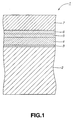
- the present invention provides an optical recording medium in which at least a heat diffusion layer, a first dielectric layer, an information recording layer and a second dielectric layer are formed in this order on a substrate and signals are recorded and/or reproduced by the light illuminated from the side of the second dielectric layer, wherein an under layer for optimizing surface properties of the heat diffusion layer is formed between the substrate and the heat diffusion layer.
- the surface properties of the heat diffusion layer are optimized by the under layer provided between the substrate and the heat diffusion layer.
- those of the first dielectric layer, information recording layer and the second dielectric layer, formed on the heat diffusion layer are also optimized. This reduces the noise to realize a high C/N and optimum recording and/or reproducing characteristics.
- the present invention provides a method for preparing an optical recording medium in which at least a heat diffusion layer, a first dielectric layer, an information recording layer and a second dielectric layer are formed in this order on a substrate and signals are recorded and/or reproduced by the light illuminated from the side of the second dielectric layer, wherein the method includes forming an under layer for optimizing surface properties of the heat diffusion layer, and subsequently forming the heat diffusion layer on the under layer.
- the heat diffusion layer in which the heat diffusion layer is formed after forming the under layer on a substrate, the heat diffusion layer having optimum surface properties is formed to optimize the surface properties of the first dielectric layer, information recording layer and the second dielectric layer formed on the heat diffusion layer.
- an optical recording medium may be provided which has a reduced noise and a high C/N to realize optimum recording and/or reproducing characteristics.
- surface properties of the heat diffusion layer may be optimized to optimize the surface properties of the first dielectric layer, information recording layer and the second dielectric layer formed on the heat diffusion layer.
- the manufacturing method for the optical recording medium according to the present invention in which the under layer is formed on a substrate and subsequently the heat diffusion layer is formed, it is possible to optimize surface properties of the heat diffusion layer and hence the first dielectric layer, information recording layer and the second dielectric layer formed on the heat diffusion layer.
- the manufacturing method for the optical recording medium it is possible to produce an optical recording medium having reduced noise and a high C/N to realize optimum recording and/or reproducing characteristics.
- the present invention is applied to a magneto-optical disc having a disc substrate formed of a resin material to a disc shape and plural layers inclusive of a magneto-optical recording layer formed on the substrate.
- the magneto-optical disc according to the present invention is of the type in which light is illuminated by an optical head lying close to the magneto-optical recording layer, as in a flying optical head, from the layered film side, that is from the opposite side with respect to the disc substrate.
- this magneto-optical disc 1 includes an under layer 3, a heat diffusion layer 4, a first dielectric layer 5, a magneto-optical recording layer 6, and a second dielectric layer 7, layered in this sequence.
- the disc substrate 2 is molded in a disc shape by injection molding of a resin material, such as polycarbonate (PC).
- a resin material such as polycarbonate (PC).
- the role of the under layer 3 is to optimize surface properties of the heat diffusion layer 4 formed on the under layer 3.
- the under layer 3 is e.g., a SiFeCoCr film of a film thickness of the order of 10 nm, formed on the disc substrate 2.
- the role of the heat diffusion layer 4 is to diffuse the heat due to light illuminated on the magneto-optical recording layer 6 and to improve the reflectance of the light to improve recording characteristics of the magneto-optical recording layer 6.
- an Al film is formed as this heat diffusion layer 4 on the under layer 3 to a film thickness of approximately 40 mm
- the role of the first dielectric layer 5 is to improve recording characteristics of the magneto-optical disc 1.
- the first dielectric layer 5 is e.g., a SiN film of a film thickness of the order of 20 nm, formed on the heat diffusion layer 4.
- the magneto-optical recording layer 6 demonstrates the magneto-optical effect and is e.g., a TbFeCo film, that is a film employing Tb as a rare earth element and employing Fe and Co as transition metals, with a film thickness of the order of 23 nm, formed on the first dielectric layer 5.
- a TbFeCo film that is a film employing Tb as a rare earth element and employing Fe and Co as transition metals, with a film thickness of the order of 23 nm, formed on the first dielectric layer 5.
- the second dielectric layer 7 is e.g., a SiN film, formed to a film thickness of the order of 80 nm on the magneto-optical recording layer 6.
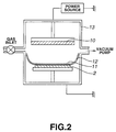
- the above-mentioned layers, formed on the disc substrate 2 are formed by sequentially depositing materials of the layers on the disc substrate 2 by thin film forming techniques, such as sputtering. That is, these layers are sequentially formed by sputtering, with the disc substrate 2 being accommodated in a vacuum chamber 13, housing therein a target 10 of the material constituting the respective layers and a mask 12 having an opening 11, as shown in Fig.2.
- the sputtering may be carried out in such a manner that, with use of a sole vacuum chamber 13, the target 10 and the mask 12 in the vacuum chamber 13 are exchanged and the vacuum chamber 13 is evacuated each time a layer is formed.
- a number of vacuum chambers equal to the number of the layers may be provided, and a target 10 and a mask 12 may then be provided in the vacuum chamber 13, with the disc substrate 2 being then sequentially accommodated in the vacuum chamber 13 to effect sputtering to form the respective layers.
- the under layer 3 formed of, for example, SiFeCoCr, is formed on the disc substrate 2.
- the heat diffusion layer 4, formed on the disc substrate 2 with the interposition of the under layer, is improved in surface properties.
- the surface roughness Ra of the heat diffusion layer 4, formed by an Al film with a film thickness of approximately 40 nm, formed on the disc substrate 2, with the interposition of the under layer 3 formed by a SiFeCoCr film, with a film thickness of approximately 40 nm, and that of the heat diffusion layer 4, directly formed on the disc substrate without the interposition of the under layer, were measured by AFM observation.
- the heat diffusion layer 4 of which is improved in surface properties, the first dielectric layer 5, magneto-optical recording layer 6 and the second dielectric layer 7, formed on the heat diffusion layer 4, are also improved in surface properties, in comparison with the magneto-optical disc the heat diffusion layer of which is directly formed on the disc substrate. This yields a magneto-optical disc 1 which is reduced in noise to improve the C/N ratio and which exhibits optimum recording and/or reproducing characteristics.
- such magneto-optical disc 1 is taken as an example, in which the under layer 3 is formed by a SiFeCoCr film of a film thickness of approximately 10 nm, the heat diffusion layer 4 is formed by an Al film of a film thickness of approximately 40 nm, the first dielectric layer 5 is formed by a SiN film of a film thickness of approximately 20 nm, the magneto-optical recording layer 6 is formed by a TbFeCo film of a film thickness of approximately 23 nm, and the second dielectric layer 7 is formed by a SiN film of a film thickness of approximately 80 nm.
- the preferred embodiment is not limited to these specified materials or film thicknesses of the respective layers of the magneto-optical disc 1.
- TbFeCo, TbFeCoCr, SiN, ZnS ⁇ SiO 2 , SiO 2 or diamond-like carbon may also be preferably used in addition to SiFeCoCr.
- the illustrated materials are particularly desirable because these materials exhibit the effect of optimizing the surface properties of the heat diffusion layer 4 and hence the recording and/or reproducing performance of the magneto-optical disc 1.
- the film thickness of the under layer 3 is not limited to the above given values, the film thickness of the order of 5 to 15 nm is desirable.
- the material for the heat diffusion layer 4 As the material for the heat diffusion layer 4, AlTi, AlMg or AlSi, for example, may be used in place of Al.
- the film thickness of the heat diffusion layer 4 is not limited to the above given values and may desirably be of the order of 20 to 50 nm.
- the material for the first dielectric layer 5 ZnS, SiO 2 etc may also be used in addition to SiN.
- the film thickness of the first dielectric layer 5 is not limited to the above given values, the film thickness of the first dielectric layer 5 of the order of 15 to 35 nm is desirable.
- TbFeCo mixed with additives such as Cr or Ni, DyFeCo, GdFeCo or films of alloys thereof may be used in addition to TbFeCo.
- the film thickness of the magneto-optical recording layer 6 is not limited to that given above, the film thickness of the order of 15 to 120 nm is desirable.
- the magneto-optical recording layer 6 may be formed by co-sputtering, using targets such as Tb, Dy, Gd, Fe, Co or FeCo, in addition to by sputtering sing alloy targets.
- the material of the second dielectric layer 7 ZnS, SiO 2 etc may be used in addition to SiN.
- the film thickness of the second dielectric layer 7 is not limited to the value given above, it is preferably of the order of 40 to 110 nm.
- the gas pressure in forming the under layer 3 by sputtering is desirably set to 0.4 to 0.8 Pa.
- the under layer 3 of which is formed by sputtering at a gas pressure ranging from 0.4 to 0.8 Pa it is possible to realize optimum recording and/or reproducing characteristics.
- the gas pressure in forming the heat diffusion layer 4 by sputtering is desirably set to 0.1 to 0.6 Pa.
- the heat diffusion layer 4 of which is formed by sputtering at a gas pressure ranging from 0.1 to 0.6 Pa it is possible to realize optimum recording and/or reproducing characteristics.
- the power source of the sputtering for depositing the respective layers may be DC or AC, whichever is desired.
- the present invention is not limited to this magneto-optical disc 1.
- the present invention may be applied to an optical recording medium operating under different recording systems, such as a phase-change optical disc configured for recording and/or reproducing the information by exploiting the phase changes of the information recording layer.
- a target as a material of the under layer and a mask having a circular opening are mounted in a vacuum chamber.
- a disc substrate formed of polycarbonate is accommodated and the chamber is evacuated to approximately 5 ⁇ 10 -5 Pa.
- the under layer is formed to a film thickness of the order of 10 nm by introducing an Ar gas at a gas pressure of the order of 0.5 Pa into the vacuum chamber, and by performing sputtering with a target which is to form the under layer, to form the under layer to a film thickness of the order of 10 nm.
- SiFeCoCr, TbFeCo, TbFeCoCr, SiN, ZnS, ZnS ⁇ SiO 2 , SiO 2 , C, Si or FeCo are used.
- diamond-like carbon abbreviated herein to DLC, is formed by sputtering by mixing nitrogen or hydrogen into an Ar gas during film forming, using a C target.
- an AlMg target and a mask having a circular opening are installed in a vacuum chamber.
- the 10 disc substrates, carrying the under layers, and the sole disc substrate, not carrying the under layer are sequentially accommodated in the vacuum chamber, which then is again evacuated to approximately 5 ⁇ 10 -5 Pa.
- an Ar gas is introduced under a gas pressure of approximately 0.4 Pa and sputtering by the AlMg target is carried out to form a heat diffusion layer formed by an AlMg film of the order of 40 nm on each of the 10 disc substrates carrying the under layers and the sole disc substrate not carrying the under layer.
- a dielectric layer is formed on each of the 11 disc substrates, carrying the heat diffusion layers.
- a Si target and a mask having a circular opening are mounted in a vacuum chamber.
- 11 disc substrates, carrying heat diffusion layers, are sequentially accommodated in the vacuum chamber.
- a N2 gas is introduced into the vacuum chamber, and the gas pressure is set at approximately 0.4 Pa.
- reactive sputtering by a Si target then is carried out to form a first dielectric layer of SiN with a film thickness of approximately 20 nm on each of the 11 disc substrates now carrying the heat diffusion layers 4.
- a magneto-optical recording layer 1 is formed on each of the 11 disc substrates, now carrying the first dielectric layers.
- a TbFeCo target and a mask having a circular opening are mounted in the vacuum chamber.
- 11 disc substrates, now carrying the first dielectric layers, are sequentially; accommodated in the vacuum chamber, which is again evacuated to approximately 5 ⁇ 10 -5 Pa.
- An Ar gas is introduced into the vacuum chamber, at a gas pressure of the order of 0.6 Pa, and sputtering is carried out by the TbFeCo target to form a magneto-optical layer of TbFeCo with a film thickness of approximately 23 nm on each of the 11 disc substrates carrying the first dielectric layer.
- a Si target and a mask having a circular opening are mounted within the vacuum chamber.
- 11 disc substrates carrying the magneto-optical recording layers
- the N 2 gas is introduced, along with the Ar gas, into the vacuum chamber.
- the gas pressure is set to the order of 0.4 Pa.
- a second dielectric layer of SiN with a film thickness of the order of 80 nm, is formed on each of the 11 disc substrates, carrying the magneto-optical recording layer, by sputtering, using a Si target.
- SiN silicon target
- the information was recorded by a recording and/or reproducing apparatus and the C/N ratio on reproducing the recorded information and the noise level on erasing the recorded information at 1 MHz (erasure noise: EN) were checked to evaluate the recording and/or reproducing characteristics.
- a recording and/or reproducing apparatus having a rotational driving system for rotationally driving the disc at a linear speed of approximately 6.5 m/sec, a light source of a wavelength of 680 nm and an objective lens with a numerical aperture NA of 0.6 was used.
- the information with the frequency of 6.25 MHz was recorded on each of the 11 magneto-optical discs, with the recording magnetic field of 300 Oe, and with the recording power set to a high level of 10 mW and a low level of 0.5 mW.
- the information recorded on the 11 magneto-optical discs was reproduced with the reproducing power of 1 mW and the C/N ratio was measured at the same time as the erasure noise (EN) on erasing the information recorded on the 11 magneto-optical discs was measured.
- EN erasure noise
- SiFeCoCr was used as the under layer material.
- a magneto-optical disc with a film thickness of 1 nm of the under layer (Comparative Example 2), a magneto-optical disc with a film thickness of 5 nm of the under layer (Example 11), a magneto-optical disc with a film thickness of 10 nm of the under layer (Example 12), a magneto-optical disc with a film thickness of 15 nm of the under layer (Example 13) and magneto-optical disc with a film thickness of 20 nm of the under layer (Comparative Example 3), were prepared.
- the magneto-optical discs with the film thicknesses of the under layers of 5 to 15 nm are higher in C/N and lower in EN than a magneto-optical disc with the film thickness of the under layer of 1 nm (Comparative Example 2) or a magneto-optical disc with the film thickness of the under layer of 20 nm. It is thus seen that, if the film thickness of the under layer of a magneto-optical disc is set to 5 to 15 nm, a particularly high C/N and appreciably low EN are realized to realize particularly superior recording and/or reproducing characteristics.
- Example 14 and 15 and Comparative Examples 4 to 6 Five magneto-optical discs (Examples 14 and 15 and Comparative Examples 4 to 6) were prepared as the gas pressure of the Ar gas in forming the under layer by sputtering was changed and measurements were made of the erasure noise (EN) and C/N of the respective magneto-optical discs to check into the gas pressure dependency of the recording and/or reproducing characteristics in generating the under layers.
- EN erasure noise
- a magneto-optical disc having an under layer formed at the Ar gas pressure of 0.1 Pa (Comparative Example 4), a magneto-optical disc having an under layer formed at the Ar gas pressure of 0.2 Pa (Comparative Example 5), a magneto-optical disc having an under layer formed at the Ar gas pressure of 0.4 Pa (Example 14), a magneto-optical disc having an under layer formed at the Ar gas pressure of 0.8 Pa (Example 15) and a magneto-optical disc having an under layer formed at the Ar gas pressure of 1.0 Pa (Comparative Example 6) were prepared.
- the magneto-optical discs having the under layers formed at an Ar gas pressure of 0.4 to 0.8 Pa are higher in C/N and lower in EN than the magneto-optical disc having the under layer formed at an Ar gas pressure of 0.1 Pa (Comparative Example 4), magneto-optical discs having the under layers formed at an Ar gas pressure of 0.2 Pa (Comparative Example 5) or the magneto-optical disc having the under layer formed at an Ar gas pressure of 1.0 Pa (Comparative Example 6).
- the gas pressure of the Ar gas in forming the under layer to 0.4 to 0.8 Pa, a particularly high C/N can be realized with an appreciably low EN to produce optimum recording and/or reproducing characteristics.
- Examples 16, 17 and Comparative Examples 7,8 Four magneto-optical discs with different types of the materials of the heat diffusion layer (Examples 16, 17 and Comparative Examples 7,8) were prepared and the erasure noise (EN) and the C/N of the respective magneto-optical discs were measured to check into the heat diffusion layer material dependency of the recording and/or reproducing characteristics.
- EN erasure noise
- SiFeCoCr was used as a material of the under layer.
- a magneto-optical disc having the heat diffusion layer of AlMg (Example 16)
- a magneto-optical disc having the heat diffusion layer of AlAg (Example 17)
- a magneto-optical disc having the heat diffusion layer of Al (Comparative Example 7)
- a magneto-optical disc having the heat diffusion layer of AlTi (Comparative Example 8) were prepared.
- the C/N and EN of the respective magneto-optical discs were checked by the same method as that used in Experiment 1. The results are shown in Table 4.
- the magneto-optical disc having a heat diffusion layer of AlMg (Example 16) or the magneto-optical disc having a heat diffusion layer of AlAg (Example 17) are higher in C/N and lower in EN than a magneto-optical disc having a heat diffusion layer of Al (Comparative Example 7) or a magneto-optical disc having a heat diffusion layer of AlTi (Comparative Example 8). This is presumably due to the fact that use of AlMg or AlAg as a material of the heat diffusion layer yields surface properties better than those obtained by using Al or AlTi.
- the magneto-optical disc is particularly high in S/N and appreciably reduced in EN to yield particularly satisfactory recording and/or reproducing characteristics.
- a magneto-optical disc having an heat diffusion layer formed at the Ar gas pressure of 0.1 Pa Example 18
- a magneto-optical disc having an heat diffusion layer formed at the Ar gas pressure of 0.2 Pa Example 19
- a magneto-optical disc having an heat diffusion layer formed at the Ar gas pressure of 0.6 Pa Example 20
- a magneto-optical disc having an heat diffusion layer formed at the Ar gas pressure of 0.8 Pa Example 9
- a magneto-optical disc having an heat diffusion layer formed at the Ar gas pressure of 1.0 Pa (Comparative Example 10) were prepared.
- the magneto-optical discs having the heat diffusion layers formed under the Ar gas pressure of 0.1 to 0.6 Pa are higher in C/N and lower in EN than the magneto-optical disc having the heat diffusion layers formed under the Ar gas pressure of 0.8 Pa (Comparative Example 9) or the magneto-optical disc having the heat diffusion layers formed under the Ar gas pressure of 1.0 Pa (Comparative Example 10). It is thus seen that, by setting the gas pressure of the Ar gas to 0.1 to 0.6 Pa in forming the heat diffusion layer of the magneto-optical disc, a particularly high C/N is obtained and the EN is appreciably reduced to realize optimum recording and/or reproducing characteristics. Meanwhile, the gas pressure lower than 0.1 Pa is not desirable because then the heat diffusion layer is difficult to form by sputtering because of the excessively low gas pressure.
Landscapes
- Engineering & Computer Science (AREA)
- Manufacturing & Machinery (AREA)
- Chemical & Material Sciences (AREA)
- Inorganic Chemistry (AREA)
- Optical Record Carriers And Manufacture Thereof (AREA)
Applications Claiming Priority (2)
| Application Number | Priority Date | Filing Date | Title |
|---|---|---|---|
| JP10350536A JP2000173119A (ja) | 1998-12-09 | 1998-12-09 | 光学記録媒体及びその製造方法 |
| JP35053698 | 1998-12-09 |
Publications (2)
| Publication Number | Publication Date |
|---|---|
| EP1014352A2 true EP1014352A2 (fr) | 2000-06-28 |
| EP1014352A3 EP1014352A3 (fr) | 2001-07-11 |
Family
ID=18411161
Family Applications (1)
| Application Number | Title | Priority Date | Filing Date |
|---|---|---|---|
| EP99124465A Withdrawn EP1014352A3 (fr) | 1998-12-09 | 1999-12-08 | Support d'enregistrement optique et son procédé de fabrication |
Country Status (5)
| Country | Link |
|---|---|
| US (1) | US6277462B1 (fr) |
| EP (1) | EP1014352A3 (fr) |
| JP (1) | JP2000173119A (fr) |
| KR (1) | KR20000047982A (fr) |
| SG (1) | SG90082A1 (fr) |
Cited By (1)
| Publication number | Priority date | Publication date | Assignee | Title |
|---|---|---|---|---|
| EP1555669A1 (fr) * | 2002-10-25 | 2005-07-20 | Fujitsu Limited | Support d'enregistrement magneto-optique, procede d'enregistrement et de reproduction d'informations et dispositif d'enregistrement magnetique |
Families Citing this family (1)
| Publication number | Priority date | Publication date | Assignee | Title |
|---|---|---|---|---|
| JP2003016636A (ja) * | 2001-04-27 | 2003-01-17 | Sharp Corp | 磁気記録媒体およびそれを用いた磁気記録装置 |
Citations (2)
| Publication number | Priority date | Publication date | Assignee | Title |
|---|---|---|---|---|
| JPH04177625A (ja) * | 1990-11-09 | 1992-06-24 | Nippon Telegr & Teleph Corp <Ntt> | 熱拡散層付き光ディスク媒体およびその製造方法 |
| EP0997894A1 (fr) * | 1998-10-30 | 2000-05-03 | Fujitsu Limited | Support d'enregistrement magnétooptique et méthode de fabrication |
Family Cites Families (2)
| Publication number | Priority date | Publication date | Assignee | Title |
|---|---|---|---|---|
| DE69130441T2 (de) * | 1990-08-07 | 1999-04-08 | Hitachi Maxell | Magnetooptischer Aufzeichnungsträger |
| JPH0668532A (ja) * | 1992-08-18 | 1994-03-11 | Sony Corp | 光磁気記録媒体 |
-
1998
- 1998-12-09 JP JP10350536A patent/JP2000173119A/ja not_active Abandoned
-
1999
- 1999-12-06 US US09/455,171 patent/US6277462B1/en not_active Expired - Fee Related
- 1999-12-07 SG SG9906128A patent/SG90082A1/en unknown
- 1999-12-08 KR KR1019990055654A patent/KR20000047982A/ko active IP Right Grant
- 1999-12-08 EP EP99124465A patent/EP1014352A3/fr not_active Withdrawn
Patent Citations (2)
| Publication number | Priority date | Publication date | Assignee | Title |
|---|---|---|---|---|
| JPH04177625A (ja) * | 1990-11-09 | 1992-06-24 | Nippon Telegr & Teleph Corp <Ntt> | 熱拡散層付き光ディスク媒体およびその製造方法 |
| EP0997894A1 (fr) * | 1998-10-30 | 2000-05-03 | Fujitsu Limited | Support d'enregistrement magnétooptique et méthode de fabrication |
Non-Patent Citations (1)
| Title |
|---|
| PATENT ABSTRACTS OF JAPAN vol. 016, no. 493 (P-1435), 13 October 1992 (1992-10-13) & JP 04 177625 A (NIPPON TELEGR & TELEPH CORP), 24 June 1992 (1992-06-24) * |
Cited By (2)
| Publication number | Priority date | Publication date | Assignee | Title |
|---|---|---|---|---|
| EP1555669A1 (fr) * | 2002-10-25 | 2005-07-20 | Fujitsu Limited | Support d'enregistrement magneto-optique, procede d'enregistrement et de reproduction d'informations et dispositif d'enregistrement magnetique |
| EP1555669A4 (fr) * | 2002-10-25 | 2008-06-25 | Fujitsu Ltd | Support d'enregistrement magneto-optique, procede d'enregistrement et de reproduction d'informations et dispositif d'enregistrement magnetique |
Also Published As
| Publication number | Publication date |
|---|---|
| KR20000047982A (ko) | 2000-07-25 |
| EP1014352A3 (fr) | 2001-07-11 |
| US6277462B1 (en) | 2001-08-21 |
| SG90082A1 (en) | 2002-07-23 |
| JP2000173119A (ja) | 2000-06-23 |
Similar Documents
| Publication | Publication Date | Title |
|---|---|---|
| US20060002243A1 (en) | Manufacturing method for magneto optical recording medium | |
| CN100428334C (zh) | 磁记录介质及其制造方法、和磁记录介质的记录再生方法 | |
| US5665468A (en) | Magneto-optical recording medium | |
| EP1406253B1 (fr) | Fabrication d'un disque original pour support d'enregistrement optique | |
| EP0997894B1 (fr) | Support d'enregistrement magnétooptique et méthode de fabrication | |
| US20040057343A1 (en) | Magnetic recording medium, method for producing the same and magnetic recording/reproducing apparatus | |
| US6277462B1 (en) | Optical recording medium and method for manufacture thereof | |
| US6638597B1 (en) | Magneto-optical recording medium | |
| US5958575A (en) | Magneto-optical recording medium | |
| JP2814604B2 (ja) | 記録再生方法 | |
| JP3882483B2 (ja) | 光記録媒体の製造方法 | |
| JP2000067465A (ja) | 光記録媒体およびその製造方法 | |
| JP2555113B2 (ja) | 光学的磁気記録媒体の製造法 | |
| EP1158508A2 (fr) | Milieu d'enregistrement magnéto-optique et procédé pour sa fabrication | |
| JP2000163819A (ja) | 光磁気記録媒体 | |
| JP2000099994A (ja) | 光学記録媒体 | |
| JPH08106662A (ja) | 光磁気記録媒体 | |
| JP2000339784A (ja) | 成膜方法、光ディスクの製造方法および製造装置 | |
| JP2830385B2 (ja) | 光磁気記録媒体の製造方法 | |
| JP2001176127A (ja) | 光学記録媒体およびその製造方法 | |
| Hartmann et al. | MAGNETO-OPTIC RETM ALLOYS: THE STEPS OF INDUSTRIALIZATION | |
| JPH0785521A (ja) | 光磁気記録媒体の製造方法 | |
| JPH0896429A (ja) | 光磁気記録媒体 | |
| JPH07320303A (ja) | 光記録媒体 | |
| JPH08315435A (ja) | 光磁気記録媒体 |
Legal Events
| Date | Code | Title | Description |
|---|---|---|---|
| PUAI | Public reference made under article 153(3) epc to a published international application that has entered the european phase |
Free format text: ORIGINAL CODE: 0009012 |
|
| AK | Designated contracting states |
Kind code of ref document: A2 Designated state(s): DE FR GB NL |
|
| AX | Request for extension of the european patent |
Free format text: AL;LT;LV;MK;RO;SI |
|
| PUAL | Search report despatched |
Free format text: ORIGINAL CODE: 0009013 |
|
| AK | Designated contracting states |
Kind code of ref document: A3 Designated state(s): AT BE CH CY DE DK ES FI FR GB GR IE IT LI LU MC NL PT SE |
|
| AX | Request for extension of the european patent |
Free format text: AL;LT;LV;MK;RO;SI |
|
| 17P | Request for examination filed |
Effective date: 20011213 |
|
| AKX | Designation fees paid |
Free format text: DE FR GB NL |
|
| 17Q | First examination report despatched |
Effective date: 20021105 |
|
| STAA | Information on the status of an ep patent application or granted ep patent |
Free format text: STATUS: THE APPLICATION IS DEEMED TO BE WITHDRAWN |
|
| 18D | Application deemed to be withdrawn |
Effective date: 20030317 |