EP1013884A2 - Turbinenschaufel mit aktiv gekültem Deckbandelememt - Google Patents
Turbinenschaufel mit aktiv gekültem Deckbandelememt Download PDFInfo
- Publication number
- EP1013884A2 EP1013884A2 EP99811187A EP99811187A EP1013884A2 EP 1013884 A2 EP1013884 A2 EP 1013884A2 EP 99811187 A EP99811187 A EP 99811187A EP 99811187 A EP99811187 A EP 99811187A EP 1013884 A2 EP1013884 A2 EP 1013884A2
- Authority
- EP
- European Patent Office
- Prior art keywords
- turbine blade
- cooling
- blade according
- shroud
- open
- Prior art date
- Legal status (The legal status is an assumption and is not a legal conclusion. Google has not performed a legal analysis and makes no representation as to the accuracy of the status listed.)
- Granted
Links
Images


Classifications
-
- F—MECHANICAL ENGINEERING; LIGHTING; HEATING; WEAPONS; BLASTING
- F01—MACHINES OR ENGINES IN GENERAL; ENGINE PLANTS IN GENERAL; STEAM ENGINES
- F01D—NON-POSITIVE DISPLACEMENT MACHINES OR ENGINES, e.g. STEAM TURBINES
- F01D5/00—Blades; Blade-carrying members; Heating, heat-insulating, cooling or antivibration means on the blades or the members
- F01D5/12—Blades
- F01D5/22—Blade-to-blade connections, e.g. for damping vibrations
- F01D5/225—Blade-to-blade connections, e.g. for damping vibrations by shrouding
-
- F—MECHANICAL ENGINEERING; LIGHTING; HEATING; WEAPONS; BLASTING
- F01—MACHINES OR ENGINES IN GENERAL; ENGINE PLANTS IN GENERAL; STEAM ENGINES
- F01D—NON-POSITIVE DISPLACEMENT MACHINES OR ENGINES, e.g. STEAM TURBINES
- F01D5/00—Blades; Blade-carrying members; Heating, heat-insulating, cooling or antivibration means on the blades or the members
- F01D5/12—Blades
- F01D5/14—Form or construction
- F01D5/18—Hollow blades, i.e. blades with cooling or heating channels or cavities; Heating, heat-insulating or cooling means on blades
- F01D5/187—Convection cooling
-
- F—MECHANICAL ENGINEERING; LIGHTING; HEATING; WEAPONS; BLASTING
- F05—INDEXING SCHEMES RELATING TO ENGINES OR PUMPS IN VARIOUS SUBCLASSES OF CLASSES F01-F04
- F05B—INDEXING SCHEME RELATING TO WIND, SPRING, WEIGHT, INERTIA OR LIKE MOTORS, TO MACHINES OR ENGINES FOR LIQUIDS COVERED BY SUBCLASSES F03B, F03D AND F03G
- F05B2240/00—Components
- F05B2240/80—Platforms for stationary or moving blades
- F05B2240/801—Platforms for stationary or moving blades cooled platforms
-
- F—MECHANICAL ENGINEERING; LIGHTING; HEATING; WEAPONS; BLASTING
- F05—INDEXING SCHEMES RELATING TO ENGINES OR PUMPS IN VARIOUS SUBCLASSES OF CLASSES F01-F04
- F05D—INDEXING SCHEME FOR ASPECTS RELATING TO NON-POSITIVE-DISPLACEMENT MACHINES OR ENGINES, GAS-TURBINES OR JET-PROPULSION PLANTS
- F05D2240/00—Components
- F05D2240/80—Platforms for stationary or moving blades
- F05D2240/81—Cooled platforms
Definitions
- the present invention relates to the field of gas turbines. It affects an air-cooled turbine blade, which is vertical at the tip of the blade to the blade longitudinal axis extending shroud element, wherein the shroud element for the purpose of cooling a plurality of cooling holes is crossed, which on the input side with at least one through the Turbine blade in connection with the cooling air duct running at the tip of the blade stand and on the output side in the outside space surrounding the turbine blade flow out.
- Generic turbine blades are from DE 198 13 173 A1 or from US 5,785,496.
- the basic idea of the invention is, on the one hand, to guide the cooling bores through the shroud element in such a way that a high heat transfer between the shroud element and cooling air is ensured and, on the other hand, to allow these bores to open into the outside space in such a way that the exposed regions of the shroud reliably depend on Cooling air is applied and additionally cooled. This is achieved by proceeding from the cooling channel of the blade in the area of the shroud element, the cooling holes running essentially parallel to the direction of movement of the shovel tip from the inside to the outside and each opening in front of the outer edge of the shroud element in a recess in the surface open to the outside.
- recesses are made in the cover band element near the outer edge from the top, into which the cooling holes open laterally.
- the outlet of the cooling air on the top of the shroud element is particularly effective if, according to a preferred development, mutually spaced sealing ribs are provided on the top of the shroud element, which form a cavity in cooperation with the opposite housing wall of the gas turbine, and the cooling holes in open this cavity.
- the escaping cooling air leads to a pressure build-up in the cavity, as a result of which the penetration of hot gases is reduced.
- the side edges of the Shroud elements recesses into which the cooling holes open.
- the recesses Opposing shroud elements form a gap.
- the cooling air is divided into two partial flows. A part flows to the top and feeds the cavity mentioned between the spaced Sealing ribs with the above-mentioned effect.
- the other part flows to Underside of the cover tape and mixes there with the hot gases under setting a mixing temperature that reduces the thermal load in this area. Due to the gap geometry, the ratio of those flowing up and down can Partial quantities are influenced.
- the holes can be created using the so-called "STEM drilling” process.
- STEM drilling which has been described, for example, in US Pat. No. 5,306,401 in connection with the production of cooling holes in turbine blades, can be used to produce cooling bores with improved heat transfer properties simply and reliably.
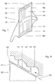
- the turbine blade 10 comprises the actual one Blade profile 23 and one arranged transversely thereto at the tip of the blade Shroud element 11, which together with the shroud elements of the other Buckets (not shown) a continuous, mechanically stabilizing Cover band results.
- the blade profile 23 is partially hollow inside and of one or several cooling air channels 18, the cooling air from the blade root to the tip of the blade.
- the shroud element 11 has on its top 22 two sealing ribs running parallel in the direction of movement of the blade tip 12 and 13, which together with the opposite housing wall 20 of the gas turbine form a cavity 21 connected to the surroundings by gaps.
- cooling bores 17 are on the input side with the cooling air duct 18 in connection and are supplied by this with cooling air.
- the cooling bores 17 do not extend all the way to the side End or edge of the shroud element 11, but each open from the side into an elongated, on the top 22 in the shroud element 11 recessed recess 14.
- each of the cooling holes 17 taken for themselves can be connected to a separate depression.
- the cooling holes 17 slightly oblique and parallel to each other to be different if it is to optimize cooling over the entire area of the shroud element 11 is necessary.
- the cooling bores 17 in the cooling arrangement shown are preferably produced using the so-called "STEM drilling" method, which is described in detail in US Pat. No. 5,306,401. This makes it possible (by changing the feed) to equip the surface of the cooling bores 17 with roughness, ribs or turbulators. This leads to significantly more efficient cooling because the shape of the cooling hole can be optimized. Furthermore, it is advantageous to provide the cooling bores 17, preferably on the inlet side, ie in the area of the cooling air supply on the profile 23, with a throttle point 19. This makes it possible to limit the cooling air mass flow in a targeted manner and to obtain significantly more efficient cooling.
- the embodiment according to FIG. 2 differs from that according to FIG.
- cooling bores 17 are designed as a diffuser or similar to a diffuser from the throttle point 19, which is arranged on the input side of each cooling bore.
- the cooling holes have an oval configuration. This, like the provision of internal roughness or the diffuser-like enlargement, increases the effective surface available for heat transfer.
- the cooling bores 17 can have different configurations than those described above. As such, regular or irregular depressions or corrugations are conceivable.
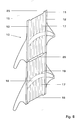
- the cooling bores 17 emerge on the side edge 25 of the shroud element 11.
- the side edges 25 of the shroud elements 11 are, however, designed such that adjacent elements 11 are only in contact in some areas, but the area of the emerging cooling bores is in contrast recessed in a recess 15. Between the adjacent elements, the opposite depressions 15 form gaps 26 into which the cooling air enters.
- This design reliably prevents the mouths from being closed by adjacent shroud elements. It ensures that the cooling air can always pass through the cooling bores 17, even if two adjacent cover band elements 11 are in mechanical contact.
- the cooling air entering the gap 26 from the two adjacent elements 11 is divided into two partial flows.
- the ratio of the two partial flows can be influenced by the design of the gap.
- the top and bottom sides can have a different gap width or the boundary walls can be inclined or differently designed in terms of flow technology.
- FIG 8 shows an embodiment with a coolant outlet on the underside of the Shroud element.
- the cooling bores 17 open laterally into the recess 16. According to this variant, the mixing temperature in the area of the bottom of the Cover band lowered and thus the thermal load is reduced.
Abstract
Description
- Stossen zwei Deckbandelemente benachbarter Schaufeln seitlich aneinander (wie dies z.B. aus Fig. 3 der US 5,482,435 zu ersehen ist), werden die Mündungen der Kühlbohrungen zumindest teilweise verschlossen. Dies behindert Kühlluftaustritt und -verteilung. Das Deckbandelement wird im Betrieb überhitzt.
- Die bekannte Deckbandkühlung ändert wegen der seitlich angeordneten Mündungen nicht die Überströmbedingungen über das Deckband, das heisst, Druck und Temperatur auf der Oberseite des Deckbandes bleiben gleich. Dies wird auch nicht dadurch geändert, dass- wie in der US 5,460,486 vorgeschlagen - gewisse Kühlbohrungen auf der Unterseite des Deckbandelementes münden.
- Die Kühlwirkung beruht hauptsächlich auf der durch Vermischung der austretenden Kühlluft mit dem Heissgas abgesenkten Mischtemperatur in der Deckband umgebung. Es werden in den Kühlbohrungen keine Massnahmen getroffen, um den Wärmeübergang zwischen der Kühlluft und dem Deckbandelement zu intensivieren.
Dies wird erreicht, indem vom Kühlkanal der Schaufel ausgehend im Bereich des Deckbandelements die Kühlbohrungen im wesentlichen parallel zur Bewegungsrichtung der Schaufelspitze von innen nach aussen verlaufen und jeweils vor dem äusseren Rand des Deckbandelementes in eine zum Aussenraum hin offene Vertiefung der Oberfläche münden.
Durch Vermischen der austretenden Kühlluft mit den heissen Verbrennungsgasen, welche über die Oberseite des Deckbandelementes strömen, wird die Temperatur in diesem Bereich wirksam herabgesetzt und so eine Überhitzung des Deckbandes vermieden. Hierdurch wird eine gleichmässige Kühlung des Deckbandelements über die gesamte Fläche erreicht.
Neben einer wirkungsvollen Kühlung der Deckbandoberseite hat diese Konfiguration auch den Vorteil einer sehr einfachen Herstellung.
Besonders wirksam ist der Auslass der Kühlluft auf der Oberseite des Deckbandelementes, wenn gemäss einer bevorzugten Weiterbildung auf der Oberseite des Deckbandelementes parallel zueinander verlaufende, voneinander beabstandete Dichtrippen vorgesehen sind, welche im Zusammenwirken mit der gegenüberliegenden Gehäusewand der Gasturbine eine Kavität bilden, und die Kühlbohrungen in diese Kavität münden. Die austretende Kühlluft führt zu einem Druckaufbau in der Kavität, in dessen Folge das Eindringen von Heissgasen vermindert wird.
Die Mittel zur Verbesserung des Wärmeübergangs an den Bohrungswänden können Rauhigkeiten, Rippen und/oder Turbulatoren umfassen. In an sich bekannter Weise können die Bohrungen mittels des sogenannten "STEM drilling"-Prozesses erstellt werden. Insbesondere durch das "STEM drilling", das beispielsweise in der US 5,306,401 im Zusammenhang mit der Herstellung von Kühllöchern in Turbinenschaufeln beschrieben worden ist, lassen sich einfach und zuverlässig Kühlbohrungen mit verbesserten Wärmeübergangseigenschaften erzeugen.
- Fig.1
- Draufsicht einer bevorzugten Ausführungsform der Turbinenschaufel mit zur Deckbandoberseite hin austretenden Kühlbohrungen
- Fig.2
- eine weitere Ausführungsform gemäss Fig.1 mit diffusorartigen Kühlbohrungen
- Fig.3
- Seitenansicht eines Deckbandelements gemäss Fig.1 mit Kühlbohrungen von kreisförmigem Querschnitt
- Fig.4
- Seitenansicht eines Deckbandelements gemäss Fig.1 mit Kühlbohrungen von ovalem Querschnitt
- Fig.5
- Teilschnittdarstellung eines Deckbandelements gemäss Fig.1
- Fig.6
- Draufsicht zweier Deckbandelemente in einer Ausführungsform mit zur Seitenkante hin austretenden Kühlbohrungen
- Fig.7
- Teilschnittdarstellung eines Deckbandelements gemäss Fig.6
- Fig.8
- Teilschnittdarstellung eines Deckbandelements mit Kühlluftaustritt zur Unterseite des Deckbandelements hin
Die Ausführungsform gemäss Fig.2 unterscheidet sich von jener gemäss Fig.1 darin, dass die Kühlbohrungen 17 ab der Drosselstelle 19, welche jeweils an der Eingangsseite jeder Kühlbohrung angeordnet ist, als Diffusor oder diffusorähnlich ausgebildet sind.
Nach einer weiteren Ausführungsform - dargestellt in Fig.4 - weisen die Kühlbohrungen eine ovale Konfiguration auf. Dies erhöht, wie die Ausrüstung mit inneren Rauhigkeiten oder die diffusorartige Erweiterung, die zur Wärmeübertragung zur Verfügung stehende wirksame Oberfläche.
Die Kühlbohrungen 17 können darüber hinaus oder alternativ andere Konfigurationen aufweisen als die oben beschriebenen. Als solche sind beispielsweise regelmässig oder unregelmässig gehaltene Vertiefungen oder Wellungen denkbar.
Diese Ausführung verhindert zuverlässig ein Verschliessen der Mündungen durch benachbarte Deckbandelemente. Sie gewährleistet, dass die Kühlluft immer durch die Kühlbohrungen 17 hindurchtreten kann, auch wenn zwei benachbarte Deckbandelemente 11 in mechanischem Kontakt stehen.
Die aus beiden benachbarten Elementen 11 in den Spalt 26 eintretende Kühlluft teilt sich in zwei Teilströme auf. Ein Teilstrom strömt nach oben und führt zu einem Aufblasen der Kavität 21 oberhalb des Deckbandes, während der andere Teilstrom auf die Unterseite des Deckbandes gelangt und sich dort mit den Heissgasen mischt. Die sich einstellende Mischtemperatur verringert die thermische Belastung in diesem Bereich.
Durch die konstruktive Gestaltung des Spaltes kann das Mengenverhältnis der beiden Teilströme beeinflusst werden. So können Ober- und Unterseite eine unterschiedliche Spaltweite aufweisen oder die Begrenzungswände geneigt oder strömungstechnisch unterschiedlich ausgebildet sein.
- 10
- Turbinenschaufel
- 11
- Deckbandelement
- 12,13
- Dichtrippen
- 14,15,16
- Vertiefung
- 17
- Kühlbohrunq
- 18
- Kühlluftkanal
- 19
- Drosselstelle
- 20
- Gehäusewand
- 21
- Kavität
- 22
- Oberseite (Deckbandelement)
- 23
- Schaufelprofil
- 24
- Heissgas
- 25
- Aussenkante des Deckbandelements
- 26
- Spalt zwischen den Deckbandelementen
Claims (14)
- Luftgekühlte Turbinenschaufel (10), welche an der Schaufelspitze ein sich senkrecht zur Schaufellängsachse erstreckendes Deckbandelement (11) aufweist, wobei das Deckbandelement (11) zwecks Kühlung von einer Mehrzahl von Kühlbohrungen (17) durchzogen ist, welche eingangsseitig mit wenigstens einem durch die Turbinenschaufel (10) zur Schaufelspitze verlaufenden Kühlluftkanal (18) in Verbindung stehen, und ausgangsseitig in den die Turbinenschaufel (10) umgebenden Aussenraum münden,
dadurch gekennzeichnet, dass
die Kühlbohrungen (17) in dem Deckbandelement (11) zumindest annähernd parallel zur Bewegungsrichtung der Schaufel (10) von innen nach aussen verlaufen und jeweils vor dem äusseren Rand (25) des Deckbandelements (11) in eine zum Aussenraum hin offene Oberflächenvertiefung (14) und/oder (15) münden. - Turbinenschaufel nach Anspruch 1,
dadurch gekennzeichnet, dass
die zum Aussenraum hin offene Vertiefung (14) auf der Oberseite (22) des Deckbandelements (11) angeordnet ist und die Kühlbohrungen (17) seitlich in diese Vertiefung (14) münden. - Turbinenschaufel nach Anspruch 1,
dadurch gekennzeichnet, dass
die zum Aussenraum hin offene Vertiefung (15) an der Seitenkante (25) des Deckbandelements (11) angeordnet ist. - Turbinenschaufel nach einem der Ansprüche 1 bis 3,
dadurch gekennzeichnet, dass
auf der Oberseite (22) des Deckbandelementes (11) mindestens zwei parallel zur Bewegungsrichtung der Schaufel verlaufende, voneinander beabstandete Dichtrippen (12, 13) vorgesehen sind, welche im Zusammenwirken mit der gegenüberliegenden Gehäusewand (20) der Gasturbine eine Kavität (21) bilden. - Turbinenschaufel nach Anspruch 4,
dadurch gekennzeichnet, dass
die Kühlbohrungen (17) über die Vertiefungen (14) in die Kavität (21) münden. - Turbinenschaufel nach Anspruch 4,
dadurch gekennzeichnet, dass
die Kühlbohrungen (17) in einen von den Vertiefungen (15) gebildeten Spalt (26) münden, und zumindest ein Teilstrom der dort austretenden Kühlluft in die Kavität (21) einströmt. - Turbinenschaufel nach Anspruch 6,
dadurch gekennzeichnet, dass
das Mengenverhältnis der aus dem Spalt (26) in Richtung Deckbandoberseite und -unterseite austretenden Teilströme durch die Spaltgeometrie gesteuert wird. - Turbinenschaufel nach einem der Ansprüche 1 bis 7,
dadurch gekennzeichnet, dass
in den Kühlbohrungen (17) Mittel zur Verbesserung des Wärmeübergangs zwischen Kühlluft und Deckbandelement (11) vorgesehen sind. - Turbinenschaufel nach Anspruch 8,
dadurch gekennzeichnet, dass
die Mittel zur Verbesserung des Wärmeübergangs an den Bohrungswänden (17) Rauhigkeiten, Rippen und/oder Turbulatoren, umfassen. - Turbinenschaufel nach Anspruch 9,
dadurch gekennzeichnet, dass
die Kühlbohrungen (17) mittels des sogenannten "STEM drilling"-Prozesses hergestellt sind. - Turbinenschaufel nach Anspruch 1,
dadurch gekennzeichnet, dass
in den Kühlbohrungen (17) jeweils eine Drosselstelle (19) zur Begrenzung des Kühlluftmassenstromes vorgesehen ist. - Turbinenschaufel nach Anspruch 11,
dadurch gekennzeichnet, dass
die Drosselstellen (19) jeweils an der Eingangsseite der Kühlbohrungen (17) angeordnet sind. - Turbinenschaufel nach Anspruch 1,
dadurch gekennzeichnet, dass
die Kühlbohrungen (17) einen ovalen Querschnitt besitzen. - Turbinenschaufel nach Anspruch 1,
dadurch gekennzeichnet, dass
die Kühlbohrungen (17) in Strömungsrichtung einen Diffusor bilden oder diffusorähnlich ausgebildet sind.
Applications Claiming Priority (4)
| Application Number | Priority Date | Filing Date | Title |
|---|---|---|---|
| DE19860244A DE19860244B4 (de) | 1998-12-24 | 1998-12-24 | Turbinenschaufel mit aktiv gekühltem Deckbandelement |
| DE19860245 | 1998-12-24 | ||
| DE19860245A DE19860245A1 (de) | 1998-12-24 | 1998-12-24 | Turbinenschaufel mit aktiv gekühltem Deckbandelement |
| DE19860244 | 1998-12-24 |
Publications (3)
| Publication Number | Publication Date |
|---|---|
| EP1013884A2 true EP1013884A2 (de) | 2000-06-28 |
| EP1013884A3 EP1013884A3 (de) | 2003-11-05 |
| EP1013884B1 EP1013884B1 (de) | 2005-07-27 |
Family
ID=26051058
Family Applications (1)
| Application Number | Title | Priority Date | Filing Date |
|---|---|---|---|
| EP99811187A Expired - Lifetime EP1013884B1 (de) | 1998-12-24 | 1999-12-21 | Turbinenschaufel mit aktiv gekühltem Deckbandelememt |
Country Status (4)
| Country | Link |
|---|---|
| US (1) | US6340284B1 (de) |
| EP (1) | EP1013884B1 (de) |
| CN (1) | CN1260442A (de) |
| DE (1) | DE59912323D1 (de) |
Cited By (8)
| Publication number | Priority date | Publication date | Assignee | Title |
|---|---|---|---|---|
| EP1126136A2 (de) * | 1999-12-28 | 2001-08-22 | ALSTOM (Schweiz) AG | Turbinenschaufel mit luftgekühltem Deckbandelement |
| EP1267042A2 (de) * | 2001-06-14 | 2002-12-18 | Mitsubishi Heavy Industries, Ltd. | Gasturbinenschaufel mit Deckband |
| US7273347B2 (en) | 2004-04-30 | 2007-09-25 | Alstom Technology Ltd. | Blade for a gas turbine |
| CH700686A1 (de) * | 2009-03-30 | 2010-09-30 | Alstom Technology Ltd | Schaufel für eine gasturbine. |
| WO2011045346A1 (de) * | 2009-10-15 | 2011-04-21 | Abb Turbo Systems Ag | Turbinenrad |
| EP2657452A1 (de) * | 2010-12-22 | 2013-10-30 | Mitsubishi Heavy Industries, Ltd. | Turbine |
| EP2290193A3 (de) * | 2009-08-18 | 2014-07-16 | United Technologies Corporation | Kühllöcher zur Abkühlung von Vorderkantenbereichen einer Turbinenleitschaufelplattform |
| EP3550111A1 (de) * | 2018-04-06 | 2019-10-09 | United Technologies Corporation | Turbinenschaufeldeckband für einen gasturbinenmotor mit einer leistungsturbine und verfahren zur herstellung davon |
Families Citing this family (30)
| Publication number | Priority date | Publication date | Assignee | Title |
|---|---|---|---|---|
| EP1041247B1 (de) | 1999-04-01 | 2012-08-01 | General Electric Company | Gasturbinenschaufel mit einem offenen Kühlkreislauf |
| US6761534B1 (en) | 1999-04-05 | 2004-07-13 | General Electric Company | Cooling circuit for a gas turbine bucket and tip shroud |
| US6254345B1 (en) * | 1999-09-07 | 2001-07-03 | General Electric Company | Internally cooled blade tip shroud |
| US6471480B1 (en) * | 2001-04-16 | 2002-10-29 | United Technologies Corporation | Thin walled cooled hollow tip shroud |
| US20040101410A1 (en) * | 2001-10-02 | 2004-05-27 | Oleg Naljotov | Axial flow fluid machine |
| US6632069B1 (en) * | 2001-10-02 | 2003-10-14 | Oleg Naljotov | Step of pressure of the steam and gas turbine with universal belt |
| US6491498B1 (en) * | 2001-10-04 | 2002-12-10 | Power Systems Mfg, Llc. | Turbine blade pocket shroud |
| US7074006B1 (en) | 2002-10-08 | 2006-07-11 | The United States Of America As Represented By The Administrator Of National Aeronautics And Space Administration | Endwall treatment and method for gas turbine |
| EA008156B1 (ru) * | 2003-04-18 | 2007-04-27 | Олег Налётов | Ступень давления паровой/газовой турбины с универсальным бандажом |
| US7066714B2 (en) * | 2004-03-26 | 2006-06-27 | United Technologies Corporation | High speed rotor assembly shroud |
| KR100758725B1 (ko) | 2005-10-17 | 2007-09-14 | 올레지 날조토브 | 유니버설 쉬라우드를 구비한 증기/가스 터빈 압력 단 |
| US7568882B2 (en) * | 2007-01-12 | 2009-08-04 | General Electric Company | Impingement cooled bucket shroud, turbine rotor incorporating the same, and cooling method |
| US7964087B2 (en) * | 2007-03-22 | 2011-06-21 | General Electric Company | Methods and systems for forming cooling holes having circular inlets and non-circular outlets |
| US20080230396A1 (en) * | 2007-03-22 | 2008-09-25 | General Electric Company | Methods and systems for forming turbulated cooling holes |
| US7938951B2 (en) * | 2007-03-22 | 2011-05-10 | General Electric Company | Methods and systems for forming tapered cooling holes |
| US7946816B2 (en) * | 2008-01-10 | 2011-05-24 | General Electric Company | Turbine blade tip shroud |
| US7946817B2 (en) * | 2008-01-10 | 2011-05-24 | General Electric Company | Turbine blade tip shroud |
| US8057177B2 (en) * | 2008-01-10 | 2011-11-15 | General Electric Company | Turbine blade tip shroud |
| US20090180894A1 (en) * | 2008-01-10 | 2009-07-16 | General Electric Company | Turbine blade tip shroud |
| US8317461B2 (en) * | 2008-08-27 | 2012-11-27 | United Technologies Corporation | Gas turbine engine component having dual flow passage cooling chamber formed by single core |
| GB0901129D0 (en) * | 2009-01-26 | 2009-03-11 | Rolls Royce Plc | Rotor blade |
| GB0910177D0 (en) * | 2009-06-15 | 2009-07-29 | Rolls Royce Plc | A cooled component for a gas turbine engine |
| US20140064984A1 (en) * | 2012-08-31 | 2014-03-06 | General Electric Company | Cooling arrangement for platform region of turbine rotor blade |
| JP5612136B2 (ja) * | 2013-01-09 | 2014-10-22 | ファナック株式会社 | 複数の直線により形状が定義されるインペラの形成方法およびインペラ |
| US9759070B2 (en) * | 2013-08-28 | 2017-09-12 | General Electric Company | Turbine bucket tip shroud |
| EP3049633A4 (de) * | 2013-09-26 | 2016-10-26 | Diffundierte plattformkühllöcher | |
| WO2015061150A1 (en) * | 2013-10-21 | 2015-04-30 | United Technologies Corporation | Incident tolerant turbine vane gap flow discouragement |
| US10539026B2 (en) | 2017-09-21 | 2020-01-21 | United Technologies Corporation | Gas turbine engine component with cooling holes having variable roughness |
| US11255198B1 (en) * | 2021-06-10 | 2022-02-22 | General Electric Company | Tip shroud with exit surface for cooling passages |
| CN115324657A (zh) * | 2022-10-12 | 2022-11-11 | 中国航发四川燃气涡轮研究院 | 涡轮工作叶片叶冠冷却结构 |
Citations (5)
| Publication number | Priority date | Publication date | Assignee | Title |
|---|---|---|---|---|
| US5306401A (en) | 1993-03-15 | 1994-04-26 | Fierkens Richard H J | Method for drilling cooling holes in turbine blades |
| US5460486A (en) | 1992-11-19 | 1995-10-24 | Bmw Rolls-Royce Gmbh | Gas turbine blade having improved thermal stress cooling ducts |
| US5482435A (en) | 1994-10-26 | 1996-01-09 | Westinghouse Electric Corporation | Gas turbine blade having a cooled shroud |
| US5785496A (en) | 1997-02-24 | 1998-07-28 | Mitsubishi Heavy Industries, Ltd. | Gas turbine rotor |
| DE19813173A1 (de) | 1997-03-25 | 1998-10-01 | Mitsubishi Heavy Ind Ltd | Gekühlte Gasturbinen-Laufschaufel |
Family Cites Families (17)
| Publication number | Priority date | Publication date | Assignee | Title |
|---|---|---|---|---|
| US3527544A (en) * | 1968-12-12 | 1970-09-08 | Gen Motors Corp | Cooled blade shroud |
| GB1423833A (en) | 1972-04-20 | 1976-02-04 | Rolls Royce | Rotor blades for fluid flow machines |
| US3816022A (en) * | 1972-09-01 | 1974-06-11 | Gen Electric | Power augmenter bucket tip construction for open-circuit liquid cooled turbines |
| GB1605335A (en) * | 1975-08-23 | 1991-12-18 | Rolls Royce | A rotor blade for a gas turbine engine |
| US4177011A (en) | 1976-04-21 | 1979-12-04 | General Electric Company | Bar for sealing the gap between adjacent shroud plates in liquid-cooled gas turbine |
| JPS5847104A (ja) * | 1981-09-11 | 1983-03-18 | Agency Of Ind Science & Technol | ガスタ−ビンのタ−ビン動翼 |
| US5003766A (en) * | 1984-10-10 | 1991-04-02 | Paul Marius A | Gas turbine engine |
| US4902198A (en) * | 1988-08-31 | 1990-02-20 | Westinghouse Electric Corp. | Apparatus for film cooling of turbine van shrouds |
| GB2223276B (en) * | 1988-09-30 | 1992-09-02 | Rolls Royce Plc | Turbine aerofoil blade |
| GB2228540B (en) * | 1988-12-07 | 1993-03-31 | Rolls Royce Plc | Cooling of turbine blades |
| JPH03182602A (ja) * | 1989-12-08 | 1991-08-08 | Hitachi Ltd | 冷却流路を有するガスタービン翼及びその冷却流路の加工方法 |
| US5122033A (en) * | 1990-11-16 | 1992-06-16 | Paul Marius A | Turbine blade unit |
| JP3260437B2 (ja) * | 1992-09-03 | 2002-02-25 | 株式会社日立製作所 | ガスタービン及びガスタービンの段落装置 |
| GB2290833B (en) | 1994-07-02 | 1998-08-05 | Rolls Royce Plc | Turbine blade |
| GB2298246B (en) * | 1995-02-23 | 1998-10-28 | Bmw Rolls Royce Gmbh | A turbine-blade arrangement comprising a shroud band |
| JPH1113402A (ja) * | 1997-06-23 | 1999-01-19 | Mitsubishi Heavy Ind Ltd | ガスタービン冷却翼チップシュラウド |
| EP1391581B1 (de) * | 1998-02-04 | 2013-04-17 | Mitsubishi Heavy Industries, Ltd. | Rotorblatt für Gasturbinen |
-
1999
- 1999-12-21 DE DE59912323T patent/DE59912323D1/de not_active Expired - Lifetime
- 1999-12-21 EP EP99811187A patent/EP1013884B1/de not_active Expired - Lifetime
- 1999-12-23 US US09/471,410 patent/US6340284B1/en not_active Expired - Lifetime
- 1999-12-24 CN CN99124987A patent/CN1260442A/zh active Pending
Patent Citations (5)
| Publication number | Priority date | Publication date | Assignee | Title |
|---|---|---|---|---|
| US5460486A (en) | 1992-11-19 | 1995-10-24 | Bmw Rolls-Royce Gmbh | Gas turbine blade having improved thermal stress cooling ducts |
| US5306401A (en) | 1993-03-15 | 1994-04-26 | Fierkens Richard H J | Method for drilling cooling holes in turbine blades |
| US5482435A (en) | 1994-10-26 | 1996-01-09 | Westinghouse Electric Corporation | Gas turbine blade having a cooled shroud |
| US5785496A (en) | 1997-02-24 | 1998-07-28 | Mitsubishi Heavy Industries, Ltd. | Gas turbine rotor |
| DE19813173A1 (de) | 1997-03-25 | 1998-10-01 | Mitsubishi Heavy Ind Ltd | Gekühlte Gasturbinen-Laufschaufel |
Cited By (14)
| Publication number | Priority date | Publication date | Assignee | Title |
|---|---|---|---|---|
| EP1126136A2 (de) * | 1999-12-28 | 2001-08-22 | ALSTOM (Schweiz) AG | Turbinenschaufel mit luftgekühltem Deckbandelement |
| EP1126136A3 (de) * | 1999-12-28 | 2004-05-19 | ALSTOM Technology Ltd | Turbinenschaufel mit luftgekühltem Deckbandelement |
| EP1267042A2 (de) * | 2001-06-14 | 2002-12-18 | Mitsubishi Heavy Industries, Ltd. | Gasturbinenschaufel mit Deckband |
| EP1267042A3 (de) * | 2001-06-14 | 2009-06-17 | Mitsubishi Heavy Industries, Ltd. | Gasturbinenschaufel mit Deckband |
| US7273347B2 (en) | 2004-04-30 | 2007-09-25 | Alstom Technology Ltd. | Blade for a gas turbine |
| WO2010112299A1 (de) * | 2009-03-30 | 2010-10-07 | Alstom Technology Ltd. | Schaufel für eine gasturbine |
| CH700686A1 (de) * | 2009-03-30 | 2010-09-30 | Alstom Technology Ltd | Schaufel für eine gasturbine. |
| US9464529B2 (en) | 2009-03-30 | 2016-10-11 | General Electric Technology Gmbh | Blade for a gas turbine |
| EP2290193A3 (de) * | 2009-08-18 | 2014-07-16 | United Technologies Corporation | Kühllöcher zur Abkühlung von Vorderkantenbereichen einer Turbinenleitschaufelplattform |
| WO2011045346A1 (de) * | 2009-10-15 | 2011-04-21 | Abb Turbo Systems Ag | Turbinenrad |
| EP2657452A1 (de) * | 2010-12-22 | 2013-10-30 | Mitsubishi Heavy Industries, Ltd. | Turbine |
| EP2657452A4 (de) * | 2010-12-22 | 2014-06-11 | Mitsubishi Heavy Ind Ltd | Turbine |
| US9353640B2 (en) | 2010-12-22 | 2016-05-31 | Mitsubishi Hitachi Power Systems, Ltd. | Turbine |
| EP3550111A1 (de) * | 2018-04-06 | 2019-10-09 | United Technologies Corporation | Turbinenschaufeldeckband für einen gasturbinenmotor mit einer leistungsturbine und verfahren zur herstellung davon |
Also Published As
| Publication number | Publication date |
|---|---|
| CN1260442A (zh) | 2000-07-19 |
| US6340284B1 (en) | 2002-01-22 |
| DE59912323D1 (de) | 2005-09-01 |
| EP1013884A3 (de) | 2003-11-05 |
| EP1013884B1 (de) | 2005-07-27 |
Similar Documents
| Publication | Publication Date | Title |
|---|---|---|
| EP1013884B1 (de) | Turbinenschaufel mit aktiv gekühltem Deckbandelememt | |
| DE60018817T2 (de) | Gekühlte Gasturbinenschaufel | |
| EP1126136B1 (de) | Turbinenschaufel mit luftgekühltem Deckbandelement | |
| DE10001109B4 (de) | Gekühlte Schaufel für eine Gasturbine | |
| DE602005000350T2 (de) | Turbinenstatorschaufel mit verbesserter Kühlung | |
| DE19944923B4 (de) | Turbinenschaufel für den Rotor einer Gasturbine | |
| EP1270873B1 (de) | Schaufel für eine Gasturbine | |
| DE69932688T2 (de) | Kühlungsöffnungen für Gasturbinenkomponenten | |
| DE69936243T2 (de) | Gasturbinenschaufel | |
| DE3711024C2 (de) | Turbinenleitschaufel für ein Gasturbinentriebwerk | |
| DE102004003354B4 (de) | Turbinen-Laufschaufel und Gasturbine | |
| DE102006004437A1 (de) | Plattform einer Laufschaufel einer Gasturbine, Verfahren zur Herstellung einer Laufschaufel, Dichtungsplatte und Gasturbine | |
| DE1946535B2 (de) | Bauteil für ein Gasturbinentriebwerk | |
| CH698339B1 (de) | Turbinenschaufel mit gekühltem Deckband. | |
| EP2414640A1 (de) | Schaufel für eine gasturbine | |
| DE102008055590A1 (de) | Turbinenschaufel-Deckband | |
| WO2010086419A1 (de) | Gekühlte schaufel für eine gasturbine | |
| EP1006263B1 (de) | Schaufelkühlung | |
| DE69825964T2 (de) | Deckband für gasturbinenschaufelspitzen | |
| DE102004002327A1 (de) | Gekühlte Schaufel für eine Gasturbine | |
| EP3473808B1 (de) | Schaufelblatt für eine innengekühlte turbinenlaufschaufel sowie verfahren zur herstellung einer solchen | |
| DE10331635B4 (de) | Gekühlte Schaufel für eine Gasturbine | |
| DE3020517A1 (de) | Vorrichtung zum ableiten der zum auspuff hin stroemenden verbrennungsprodukte in einem verbrennungsmotor | |
| EP2331790B1 (de) | Schaufel für eine gasturbine | |
| DE10016081A1 (de) | Plattenförmiger, auskragender Bauteilabschnitt einer Gasturbine |
Legal Events
| Date | Code | Title | Description |
|---|---|---|---|
| PUAI | Public reference made under article 153(3) epc to a published international application that has entered the european phase |
Free format text: ORIGINAL CODE: 0009012 |
|
| AK | Designated contracting states |
Kind code of ref document: A2 Designated state(s): AT BE CH CY DE DK ES FI FR GB GR IE IT LI LU MC NL PT SE |
|
| AX | Request for extension of the european patent |
Free format text: AL;LT;LV;MK;RO;SI |
|
| RAP1 | Party data changed (applicant data changed or rights of an application transferred) |
Owner name: ALSTOM |
|
| RAP1 | Party data changed (applicant data changed or rights of an application transferred) |
Owner name: ALSTOM (SWITZERLAND) LTD |
|
| PUAL | Search report despatched |
Free format text: ORIGINAL CODE: 0009013 |
|
| AK | Designated contracting states |
Kind code of ref document: A3 Designated state(s): AT BE CH CY DE DK ES FI FR GB GR IE IT LI LU MC NL PT SE |
|
| AX | Request for extension of the european patent |
Extension state: AL LT LV MK RO SI |
|
| RAP1 | Party data changed (applicant data changed or rights of an application transferred) |
Owner name: ALSTOM TECHNOLOGY LTD |
|
| 17P | Request for examination filed |
Effective date: 20040430 |
|
| AKX | Designation fees paid |
Designated state(s): DE FR GB |
|
| 17Q | First examination report despatched |
Effective date: 20040709 |
|
| GRAP | Despatch of communication of intention to grant a patent |
Free format text: ORIGINAL CODE: EPIDOSNIGR1 |
|
| GRAS | Grant fee paid |
Free format text: ORIGINAL CODE: EPIDOSNIGR3 |
|
| GRAA | (expected) grant |
Free format text: ORIGINAL CODE: 0009210 |
|
| AK | Designated contracting states |
Kind code of ref document: B1 Designated state(s): DE FR GB |
|
| REG | Reference to a national code |
Ref country code: GB Ref legal event code: FG4D Free format text: NOT ENGLISH |
|
| REF | Corresponds to: |
Ref document number: 59912323 Country of ref document: DE Date of ref document: 20050901 Kind code of ref document: P |
|
| GBT | Gb: translation of ep patent filed (gb section 77(6)(a)/1977) |
Effective date: 20050917 |
|
| ET | Fr: translation filed | ||
| PLBE | No opposition filed within time limit |
Free format text: ORIGINAL CODE: 0009261 |
|
| STAA | Information on the status of an ep patent application or granted ep patent |
Free format text: STATUS: NO OPPOSITION FILED WITHIN TIME LIMIT |
|
| 26N | No opposition filed |
Effective date: 20060428 |
|
| REG | Reference to a national code |
Ref country code: FR Ref legal event code: PLFP Year of fee payment: 17 |
|
| REG | Reference to a national code |
Ref country code: DE Ref legal event code: R082 Ref document number: 59912323 Country of ref document: DE Representative=s name: ROESLER, UWE, DIPL.-PHYS.UNIV., DE Ref country code: DE Ref legal event code: R081 Ref document number: 59912323 Country of ref document: DE Owner name: ANSALDO ENERGIA IP UK LIMITED, GB Free format text: FORMER OWNER: ALSTOM TECHNOLOGY LTD., BADEN, CH Ref country code: DE Ref legal event code: R081 Ref document number: 59912323 Country of ref document: DE Owner name: GENERAL ELECTRIC TECHNOLOGY GMBH, CH Free format text: FORMER OWNER: ALSTOM TECHNOLOGY LTD., BADEN, CH |
|
| REG | Reference to a national code |
Ref country code: FR Ref legal event code: CD Owner name: ALSTOM TECHNOLOGY LTD, CH Effective date: 20161110 |
|
| REG | Reference to a national code |
Ref country code: FR Ref legal event code: PLFP Year of fee payment: 18 |
|
| PGFP | Annual fee paid to national office [announced via postgrant information from national office to epo] |
Ref country code: DE Payment date: 20161213 Year of fee payment: 18 Ref country code: GB Payment date: 20161222 Year of fee payment: 18 |
|
| PGFP | Annual fee paid to national office [announced via postgrant information from national office to epo] |
Ref country code: FR Payment date: 20161222 Year of fee payment: 18 |
|
| REG | Reference to a national code |
Ref country code: DE Ref legal event code: R082 Ref document number: 59912323 Country of ref document: DE Representative=s name: ROESLER, UWE, DIPL.-PHYS.UNIV., DE Ref country code: DE Ref legal event code: R081 Ref document number: 59912323 Country of ref document: DE Owner name: ANSALDO ENERGIA IP UK LIMITED, GB Free format text: FORMER OWNER: GENERAL ELECTRIC TECHNOLOGY GMBH, BADEN, CH |
|
| REG | Reference to a national code |
Ref country code: GB Ref legal event code: 732E Free format text: REGISTERED BETWEEN 20170824 AND 20170830 |
|
| REG | Reference to a national code |
Ref country code: FR Ref legal event code: TP Owner name: ANSALDO ENERGIA IP UK LIMITED, GB Effective date: 20171221 |
|
| REG | Reference to a national code |
Ref country code: DE Ref legal event code: R119 Ref document number: 59912323 Country of ref document: DE |
|
| GBPC | Gb: european patent ceased through non-payment of renewal fee |
Effective date: 20171221 |
|
| REG | Reference to a national code |
Ref country code: FR Ref legal event code: ST Effective date: 20180831 |
|
| PG25 | Lapsed in a contracting state [announced via postgrant information from national office to epo] |
Ref country code: FR Free format text: LAPSE BECAUSE OF NON-PAYMENT OF DUE FEES Effective date: 20180102 Ref country code: DE Free format text: LAPSE BECAUSE OF NON-PAYMENT OF DUE FEES Effective date: 20180703 |
|
| PG25 | Lapsed in a contracting state [announced via postgrant information from national office to epo] |
Ref country code: GB Free format text: LAPSE BECAUSE OF NON-PAYMENT OF DUE FEES Effective date: 20171221 |