EP3550111A1 - Turbinenschaufeldeckband für einen gasturbinenmotor mit einer leistungsturbine und verfahren zur herstellung davon - Google Patents
Turbinenschaufeldeckband für einen gasturbinenmotor mit einer leistungsturbine und verfahren zur herstellung davon Download PDFInfo
- Publication number
- EP3550111A1 EP3550111A1 EP19167563.6A EP19167563A EP3550111A1 EP 3550111 A1 EP3550111 A1 EP 3550111A1 EP 19167563 A EP19167563 A EP 19167563A EP 3550111 A1 EP3550111 A1 EP 3550111A1
- Authority
- EP
- European Patent Office
- Prior art keywords
- shroud
- area
- blade
- internal passage
- Prior art date
- Legal status (The legal status is an assumption and is not a legal conclusion. Google has not performed a legal analysis and makes no representation as to the accuracy of the status listed.)
- Granted
Links
Images

Classifications
-
- F—MECHANICAL ENGINEERING; LIGHTING; HEATING; WEAPONS; BLASTING
- F01—MACHINES OR ENGINES IN GENERAL; ENGINE PLANTS IN GENERAL; STEAM ENGINES
- F01D—NON-POSITIVE DISPLACEMENT MACHINES OR ENGINES, e.g. STEAM TURBINES
- F01D5/00—Blades; Blade-carrying members; Heating, heat-insulating, cooling or antivibration means on the blades or the members
- F01D5/12—Blades
- F01D5/14—Form or construction
- F01D5/20—Specially-shaped blade tips to seal space between tips and stator
-
- F—MECHANICAL ENGINEERING; LIGHTING; HEATING; WEAPONS; BLASTING
- F01—MACHINES OR ENGINES IN GENERAL; ENGINE PLANTS IN GENERAL; STEAM ENGINES
- F01D—NON-POSITIVE DISPLACEMENT MACHINES OR ENGINES, e.g. STEAM TURBINES
- F01D5/00—Blades; Blade-carrying members; Heating, heat-insulating, cooling or antivibration means on the blades or the members
- F01D5/12—Blades
- F01D5/14—Form or construction
- F01D5/147—Construction, i.e. structural features, e.g. of weight-saving hollow blades
-
- F—MECHANICAL ENGINEERING; LIGHTING; HEATING; WEAPONS; BLASTING
- F01—MACHINES OR ENGINES IN GENERAL; ENGINE PLANTS IN GENERAL; STEAM ENGINES
- F01D—NON-POSITIVE DISPLACEMENT MACHINES OR ENGINES, e.g. STEAM TURBINES
- F01D5/00—Blades; Blade-carrying members; Heating, heat-insulating, cooling or antivibration means on the blades or the members
- F01D5/12—Blades
- F01D5/14—Form or construction
- F01D5/18—Hollow blades, i.e. blades with cooling or heating channels or cavities; Heating, heat-insulating or cooling means on blades
- F01D5/187—Convection cooling
-
- F—MECHANICAL ENGINEERING; LIGHTING; HEATING; WEAPONS; BLASTING
- F01—MACHINES OR ENGINES IN GENERAL; ENGINE PLANTS IN GENERAL; STEAM ENGINES
- F01D—NON-POSITIVE DISPLACEMENT MACHINES OR ENGINES, e.g. STEAM TURBINES
- F01D5/00—Blades; Blade-carrying members; Heating, heat-insulating, cooling or antivibration means on the blades or the members
- F01D5/12—Blades
- F01D5/22—Blade-to-blade connections, e.g. for damping vibrations
- F01D5/225—Blade-to-blade connections, e.g. for damping vibrations by shrouding
-
- F—MECHANICAL ENGINEERING; LIGHTING; HEATING; WEAPONS; BLASTING
- F05—INDEXING SCHEMES RELATING TO ENGINES OR PUMPS IN VARIOUS SUBCLASSES OF CLASSES F01-F04
- F05D—INDEXING SCHEME FOR ASPECTS RELATING TO NON-POSITIVE-DISPLACEMENT MACHINES OR ENGINES, GAS-TURBINES OR JET-PROPULSION PLANTS
- F05D2230/00—Manufacture
- F05D2230/20—Manufacture essentially without removing material
- F05D2230/21—Manufacture essentially without removing material by casting
-
- F—MECHANICAL ENGINEERING; LIGHTING; HEATING; WEAPONS; BLASTING
- F05—INDEXING SCHEMES RELATING TO ENGINES OR PUMPS IN VARIOUS SUBCLASSES OF CLASSES F01-F04
- F05D—INDEXING SCHEME FOR ASPECTS RELATING TO NON-POSITIVE-DISPLACEMENT MACHINES OR ENGINES, GAS-TURBINES OR JET-PROPULSION PLANTS
- F05D2240/00—Components
- F05D2240/10—Stators
- F05D2240/11—Shroud seal segments
-
- F—MECHANICAL ENGINEERING; LIGHTING; HEATING; WEAPONS; BLASTING
- F05—INDEXING SCHEMES RELATING TO ENGINES OR PUMPS IN VARIOUS SUBCLASSES OF CLASSES F01-F04
- F05D—INDEXING SCHEME FOR ASPECTS RELATING TO NON-POSITIVE-DISPLACEMENT MACHINES OR ENGINES, GAS-TURBINES OR JET-PROPULSION PLANTS
- F05D2240/00—Components
- F05D2240/20—Rotors
- F05D2240/30—Characteristics of rotor blades, i.e. of any element transforming dynamic fluid energy to or from rotational energy and being attached to a rotor
- F05D2240/307—Characteristics of rotor blades, i.e. of any element transforming dynamic fluid energy to or from rotational energy and being attached to a rotor related to the tip of a rotor blade
-
- F—MECHANICAL ENGINEERING; LIGHTING; HEATING; WEAPONS; BLASTING
- F05—INDEXING SCHEMES RELATING TO ENGINES OR PUMPS IN VARIOUS SUBCLASSES OF CLASSES F01-F04
- F05D—INDEXING SCHEME FOR ASPECTS RELATING TO NON-POSITIVE-DISPLACEMENT MACHINES OR ENGINES, GAS-TURBINES OR JET-PROPULSION PLANTS
- F05D2240/00—Components
- F05D2240/55—Seals
-
- F—MECHANICAL ENGINEERING; LIGHTING; HEATING; WEAPONS; BLASTING
- F05—INDEXING SCHEMES RELATING TO ENGINES OR PUMPS IN VARIOUS SUBCLASSES OF CLASSES F01-F04
- F05D—INDEXING SCHEME FOR ASPECTS RELATING TO NON-POSITIVE-DISPLACEMENT MACHINES OR ENGINES, GAS-TURBINES OR JET-PROPULSION PLANTS
- F05D2260/00—Function
- F05D2260/20—Heat transfer, e.g. cooling
- F05D2260/202—Heat transfer, e.g. cooling by film cooling
-
- Y—GENERAL TAGGING OF NEW TECHNOLOGICAL DEVELOPMENTS; GENERAL TAGGING OF CROSS-SECTIONAL TECHNOLOGIES SPANNING OVER SEVERAL SECTIONS OF THE IPC; TECHNICAL SUBJECTS COVERED BY FORMER USPC CROSS-REFERENCE ART COLLECTIONS [XRACs] AND DIGESTS
- Y02—TECHNOLOGIES OR APPLICATIONS FOR MITIGATION OR ADAPTATION AGAINST CLIMATE CHANGE
- Y02T—CLIMATE CHANGE MITIGATION TECHNOLOGIES RELATED TO TRANSPORTATION
- Y02T50/00—Aeronautics or air transport
- Y02T50/60—Efficient propulsion technologies, e.g. for aircraft
Definitions
- This disclosure relates to turbomachinery, and more particularly, the disclosure relates to a shrouded turbine blade and method for making the same.
- Gas turbine engines include a compressor that compresses air, a combustor that ignites the compressed air and a turbine across which the compressed air is expanded. The expansion of the combustion products drives the turbine to rotate, which in turn drives rotation of the compressor.
- Gas turbine engines for applications such as helicopters incorporate a power turbine (PT) that is not mechanically coupled to the compressors in the gas generator portion of the gas turbine engine.
- the power turbine is rotationally driven by expanding gases from the gas generator portion to transmit power to a turboshaft.
- the turboshaft rotationally drives the helicopter propeller, typically at a constant speed, through a gearbox.
- Turbine blades may incorporate a shroud to provide damping. Knife edges may be provided on the shroud to seal with respect to a blade outer air seal (BOAS) to maintain tight clearances.
- BOAS blade outer air seal
- the shroud adds mass to the end of the blade, which increases stress.
- One or more pockets may be provided on the shroud to reduce weight.
- traditional manufacturing approaches may prevent the pocket from being formed in the shroud.
- a blade for a gas turbine engine includes an airfoil that includes an internal passage.
- a shroud is arranged at an end of the airfoil and has a shroud perimeter.
- Axially spaced knife edges extend radially from the shroud.
- An area is provided between the knife edges.
- a pocket is recessed into the area and is circumscribed by a perimeter edge that is arranged interiorly of the shroud perimeter.
- An outlet fluidly connects the internal passage to the pocket.
- a root supports a platform.
- the airfoil extends radially from the platform to the shroud.
- the internal passage extends from the root to the shroud.
- the airfoil extends from the platform to the shroud a span that is less than 2.6 inches (66.0 mm). In such an embodiment, the span extends in a radial direction from the platform to the shroud.
- the shroud includes axially spaced apart axial faces and circumferentially spaced apart circumferential faces.
- the axial and circumferential faces define the shroud perimeter.
- the knife edges extend to the circumferential faces.
- the shroud perimeter provides a first area.
- the knife edges include fillets.
- the second area is the area between and includes the fillets facing the pocket. The second area is in a range of 40% to 60% of the first area.
- the pocket has a third area defined by the perimeter edge.
- the third area is in a range of 80% to 90% of the second area.
- the outlet has a fourth area.
- the fourth area is in a range of 5% to 25% of the third area.
- the pocket has first and second surfaces joined at a peak.
- the outlet is arranged on at least one side of the peak.
- the pocket has first and second surfaces joined at a peak.
- the shroud has first and second thicknesses spaced in a direction perpendicular to the peak on at least one of the first and second surfaces.
- the first and second thicknesses extend in a radial direction.
- the first thickness is provided at a tangent point to a fillet that joins the shroud and the airfoil.
- the second thickness is provided at the perimeter edge. The ratio of the first thickness to the second thickness in a range of 1.1 to 2.1.
- the depth of the pocket corresponds to the location of the second thickness at the perimeter edge that is 0.060 inch (1.52 mm) or less.
- a gas turbine engine in one exemplary embodiment, includes a gas generator portion that provides an air source.
- a power turbine is arranged fluidly downstream from the gas generator portion.
- the power turbine is mechanically disconnected from the gas generator portion.
- the power turbine includes at least one stage of blades.
- Each of the blades include an airfoil that includes an internal passage.
- a shroud is arranged at an end of the airfoil and has a shroud perimeter.
- Axially spaced knife edges extend radially from the shroud.
- An area is provided between the knife edges.
- a pocket is recessed into the area and is circumscribed by a perimeter edge that is arranged interiorly of the shroud perimeter.
- An outlet fluidly connects the internal passage to the pocket.
- the shroud perimeter provides a first area.
- the knife edges include fillets.
- the second area is the area between the fillets facing the pocket.
- the pocket has a third area defined by the perimeter edge. The third area is in a range of 80% to 90% of the second area.
- the pocket has first and second surfaces joined at a peak.
- the shroud has first and second thicknesses spaced in a direction perpendicular to the peak on at least one of the first and second surfaces.
- the first and second thicknesses extend in a radial direction.
- the first thickness are provided at a tangent point to a fillet that joins the shroud and the airfoil.
- the second thickness is provided at the perimeter edge.
- the ratio of the first thickness to the second thickness is in a range of 1.1 to 2.1.
- the depth of the pocket corresponds to the location of the second thickness at the perimeter edge that is 0.060 inch (1.52 mm) or less.
- the gas turbine engine includes a root that supports a platform.
- the airfoil extends radially from the platform to the shroud.
- the internal passage extends from the root to the shroud.
- the airfoil extends from the platform to the shroud a span. The span is less than 2.6 inches (66.0 mm).
- the gas generator portion includes a compressor section.
- the power turbine is mechanically disconnected from the compressor section.
- a method of manufacturing a blade for a gas turbine engine provides an internal passage core and casts an airfoil about the internal passage core to provide the blade including an internal passage formed by the internal passage core.
- the casting step forms a shroud arranged at an end of the airfoil and forms a pocket in the shroud.
- the pocket is recessed into the area and is circumscribed by a perimeter edge that is arranged interiorly of the shroud perimeter.
- An outlet fluidly connects the internal passage to the pocket.
- the pocket is formed by a portion of the internal passage core.
- the pocket forming step includes electro-discharge that machines the pocket.
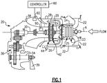
- Figure 1 schematically illustrates a gas turbine engine 20.
- the engine 20 is a turboshaft engine, such as for a helicopter.
- the engine 20 includes an inlet duct 22, a compressor section 24, a combustor section 26, and a turbine section 28.
- the compressor section 24 is an axial compressor and includes a plurality of circumferentially-spaced blades.
- the turbine section 28 includes circumferentially-spaced turbine blades.
- the compressor section 24 and the turbine section 28 are mounted on a main shaft 29 for rotation about an engine central longitudinal axis A relative to an engine static structure 32 via several bearing systems (not shown).
- the compressor section 24 draws air through the inlet duct 22.
- gas turbine engines ingest some amount of dust, such engines are typically not designed for highly dusty environments.
- Engines such as the engine 20 are subject to operating in highly dusty environments during takeoff and landing.
- the inlet duct 22 opens radially relative to the central longitudinal axis A.
- the compressor section 24 compresses the air, and the compressed air is then mixed with fuel and burned in the combustor section 26 to form a high pressure, hot gas stream.
- the hot gas stream is expanded in the turbine section 28, which may include first and second turbine 42, 44.
- the first turbine 42 rotationally drives the compressor section 24 via a main shaft 29. Together these components provide a gas generator portion of the engine 20.
- the second turbine 44 which is a power turbine in the example embodiment, rotationally drives a power shaft 30, gearbox 36, and output shaft 34.
- the power turbine 44 is mechanically disconnected from the gas generator portion. That is, the main shaft 29 and power shaft 30 are not connected to one another such that the shafts 29, 30 rotate separately and at different speeds.
- the power turbine 44 may include a single or multiple stages of blades and vanes.
- the output shaft 34 rotationally drives the helicopter rotor blades 39 used to generate lift for the helicopter.
- the hot gas stream is expelled through an exhaust 38.
- the engine 20 also includes a seal system in the turbine section 28 around the blades.
- a seal system may be referred to as a blade outer air seal (BOAS).
- BOAS blade outer air seal
- the seal system serves to provide a minimum clearance around the tips of the blades, to limit the amount of air that escapes around the tips.
- the power turbine 44 is shown in more detail in Figure 2 .
- the power turbine 44 includes stages of stator vanes 48 axially spaced apart from one another and supported with respect to the turbine case structure 46, which is part of the engine static structure 32. Stages of rotor blades 50 are axially interspersed between the stages of stator vanes 48.
- Axially spaced apart arrays of blades 50 are supported on a rotor 40 connected to the power shaft 30.
- BOAS 56 are supported by the turbine case structure 46 to provide a seal with respect to an end of the blade.
- the end of the blade includes a shroud 52 supporting radially extending knife edges 54, which cooperate with the BOAS 56 to provide a seal.
- each blade 50 includes a root 62 supporting a platform 60.
- An airfoil 58 has a span extending in a radial direction R from the platform 60 to the shroud 52.
- the span is less than 2.6 inch (66.0 mm). For blades having such a short span, it is difficult to reliably manufacture complex geometries on the surface of the blade.
- An internal passage 70 extends from the root 62 to the shroud 52 in the example shown.
- the internal passage 70 may be supplied with cooling fluid from, for example, the compressor section 24.
- the internal passage 70 may not be supplied with any cooling fluid and may be incorporated into the blade 50 to further reduce the overall weight of the blade 50.
- the shroud 52 includes a shroud perimeter 64 defined by axially spaced apart faces 66 and circumferentially spaced apart faces 68, which are spaced apart from one another in a circumferential direction C. Circumferential faces of adjacent blades typically do not contact one another.
- the knife edges 54 extend to and connect the circumferential faces 68.
- the shroud perimeter 64 provides a first area A1.
- the knife edges 54 include fillets 84.
- a second area A2 is the area between and including the fillets 84 facing a pocket 72 provided in the shroud 52 between the knife edges 54.
- the second area A2 also includes the area of the pocket 72 itself.
- the second area A2 is in a range of 40% to 60% of the first area A1.
- the pocket 72 is circumscribed by a perimeter edge 74.
- a perimeter edge defines a third area A3, which is in a range of 80% to 90% of the second area A2.
- An outlet 76 fluidly connects the internal passage 70 and the pocket 72.
- the outlet 76 has a fourth area A4, and the fourth area A4 is in a range of 5% to 25% of the third area A3.
- the pocket 72 includes first and second surfaces 78, 80, which are generally planar, joined at a peak 82. This configuration provides tapered walls that become thinner in opposing directions distant from peak 82. Fillets 53 join the airfoil 58 to the shroud 52. The thicker wall section near the airfoil 58 provides strength and resists bending moments, or curling stresses, under centrifugal loading.
- the outlet 76 is arranged on at least one side of peak 82 (although on only one side in the illustrated example).
- First and second surfaces 78, 80 form an angle, for example, in a range of 4° to 8°, relative to an untapered equivalent surface.
- the shroud 52 has first and second thicknesses T1, T2 spaced in a direction perpendicular to peak 82on at least one of the first and second surfaces 78, 80.
- the first and second thicknesses T1, T2 extend in the radial direction R.
- the first thickness T1 is provided at a tangent point to the fillet 53.
- the second thickness T2 is provided at the perimeter edge 74.
- the ratio of the first thickness T1 to the second thickness T2 is in a range of 1.1 to 2.1.
- a depth D of the pocket 72 corresponding to the location of the second thickness T2 at the perimeter edge is 0.060 inch (1.52 mm) or less.
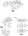
- a method of manufacturing the blade 50 is shown generally at 94 in Figure 6 .
- the method 94 includes providing an internal passage core 88 ( Figure 5 ), as indicated at block 96.
- the blade 50 is cast about the internal passage core 88, as indicated at block 98.
- the pocket 72 is formed in the shroud 52, as indicated at block 100.
- the pocket 72 is formed by a second portion 92 of the core 88, for example.
- the core 88 includes a first core portion 90 arranged within the airfoil 58 and radially beneath the shroud 52 to form the internal passage 70.
- the second core portion 92 may be a unitary, continuous structure with the first core portion 90.
- the pocket 72 is formed by electro-discharge machining (EDM).
- EDM electro-discharge machining
Landscapes
- Engineering & Computer Science (AREA)
- Mechanical Engineering (AREA)
- General Engineering & Computer Science (AREA)
- Architecture (AREA)
- Turbine Rotor Nozzle Sealing (AREA)
- Structures Of Non-Positive Displacement Pumps (AREA)
Applications Claiming Priority (1)
| Application Number | Priority Date | Filing Date | Title |
|---|---|---|---|
| US15/947,254 US10641108B2 (en) | 2018-04-06 | 2018-04-06 | Turbine blade shroud for gas turbine engine with power turbine and method of manufacturing same |
Publications (3)
| Publication Number | Publication Date |
|---|---|
| EP3550111A1 true EP3550111A1 (de) | 2019-10-09 |
| EP3550111B1 EP3550111B1 (de) | 2021-02-17 |
| EP3550111B8 EP3550111B8 (de) | 2021-04-07 |
Family
ID=66101939
Family Applications (1)
| Application Number | Title | Priority Date | Filing Date |
|---|---|---|---|
| EP19167563.6A Active EP3550111B8 (de) | 2018-04-06 | 2019-04-05 | Turbinenschaufeldeckband für einen gasturbinenmotor mit einer leistungsturbine und verfahren zur herstellung davon |
Country Status (2)
| Country | Link |
|---|---|
| US (1) | US10641108B2 (de) |
| EP (1) | EP3550111B8 (de) |
Families Citing this family (1)
| Publication number | Priority date | Publication date | Assignee | Title |
|---|---|---|---|---|
| US11053804B2 (en) * | 2019-05-08 | 2021-07-06 | Pratt & Whitney Canada Corp. | Shroud interlock |
Citations (5)
| Publication number | Priority date | Publication date | Assignee | Title |
|---|---|---|---|---|
| GB2290833A (en) * | 1994-07-02 | 1996-01-10 | Rolls Royce Plc | Turbine blade cooling |
| JPH0828303A (ja) * | 1994-07-11 | 1996-01-30 | Mitsubishi Heavy Ind Ltd | ガスタービンの動翼 |
| EP1013884A2 (de) * | 1998-12-24 | 2000-06-28 | ABB Alstom Power (Schweiz) AG | Turbinenschaufel mit aktiv gekültem Deckbandelememt |
| US6491498B1 (en) * | 2001-10-04 | 2002-12-10 | Power Systems Mfg, Llc. | Turbine blade pocket shroud |
| CH700686A1 (de) * | 2009-03-30 | 2010-09-30 | Alstom Technology Ltd | Schaufel für eine gasturbine. |
Family Cites Families (9)
| Publication number | Priority date | Publication date | Assignee | Title |
|---|---|---|---|---|
| US3990308A (en) * | 1973-11-23 | 1976-11-09 | Mccormick Robert Ian | Temperature measurement system for free turbine type gas turbine engines |
| ATE315988T1 (de) | 1999-05-24 | 2006-02-15 | Lonza Ag | Kupfer/aminoxid-holzschutzmittel |
| US6254345B1 (en) * | 1999-09-07 | 2001-07-03 | General Electric Company | Internally cooled blade tip shroud |
| US20060280610A1 (en) | 2005-06-13 | 2006-12-14 | Heyward John P | Turbine blade and method of fabricating same |
| US7527477B2 (en) | 2006-07-31 | 2009-05-05 | General Electric Company | Rotor blade and method of fabricating same |
| US7780414B1 (en) * | 2007-01-17 | 2010-08-24 | Florida Turbine Technologies, Inc. | Turbine blade with multiple metering trailing edge cooling holes |
| US8322986B2 (en) | 2008-07-29 | 2012-12-04 | General Electric Company | Rotor blade and method of fabricating the same |
| US9297267B2 (en) * | 2012-12-10 | 2016-03-29 | General Electric Company | System and method for removing heat from a turbine |
| US20170298742A1 (en) * | 2016-04-15 | 2017-10-19 | General Electric Company | Turbine engine airfoil bleed pumping |
-
2018
- 2018-04-06 US US15/947,254 patent/US10641108B2/en active Active
-
2019
- 2019-04-05 EP EP19167563.6A patent/EP3550111B8/de active Active
Patent Citations (5)
| Publication number | Priority date | Publication date | Assignee | Title |
|---|---|---|---|---|
| GB2290833A (en) * | 1994-07-02 | 1996-01-10 | Rolls Royce Plc | Turbine blade cooling |
| JPH0828303A (ja) * | 1994-07-11 | 1996-01-30 | Mitsubishi Heavy Ind Ltd | ガスタービンの動翼 |
| EP1013884A2 (de) * | 1998-12-24 | 2000-06-28 | ABB Alstom Power (Schweiz) AG | Turbinenschaufel mit aktiv gekültem Deckbandelememt |
| US6491498B1 (en) * | 2001-10-04 | 2002-12-10 | Power Systems Mfg, Llc. | Turbine blade pocket shroud |
| CH700686A1 (de) * | 2009-03-30 | 2010-09-30 | Alstom Technology Ltd | Schaufel für eine gasturbine. |
Also Published As
| Publication number | Publication date |
|---|---|
| EP3550111B8 (de) | 2021-04-07 |
| US20190309636A1 (en) | 2019-10-10 |
| US10641108B2 (en) | 2020-05-05 |
| EP3550111B1 (de) | 2021-02-17 |
Similar Documents
| Publication | Publication Date | Title |
|---|---|---|
| EP2369138B1 (de) | Gasturbinenmotor mit nicht-axialsymmetrischer, oberflächenkonturierter Schaufelplattform | |
| US7922444B2 (en) | Chamfer rail pockets for turbine vane shrouds | |
| CN112431638A (zh) | 涡轮发动机的花键 | |
| US9879542B2 (en) | Platform with curved edges adjacent suction side of airfoil | |
| EP2428644A1 (de) | Turbinenleitschaufelblatt | |
| EP2372102A2 (de) | Laufschaufelplattform einer Gasturbine | |
| WO2014035516A2 (en) | Gas turbine engine turbine vane airfoil profile | |
| EP2809882B1 (de) | Entlüftungsmuschel für eine kompressorscheibe | |
| EP2728196A2 (de) | Blutströmungskanal | |
| CN116753036A (zh) | 具有高加速度和低叶片转动的翼型件的涡轮发动机 | |
| EP3084139A2 (de) | Integral beschaufelter rotor eines gasturbinenmotor mit asymmetrischen grabenfillets | |
| EP3372785A1 (de) | Turbinenschaufelanordnung mit splittern | |
| EP3461993A1 (de) | Gasturbinenmotorschaufel | |
| EP3498978B1 (de) | Gasturbinenleitschaufel mit befestigungshaken | |
| EP3372786B1 (de) | Hochdruckverdichterrotorschaufel mit vorderkante mit einkerbungssegment | |
| EP3550111B1 (de) | Turbinenschaufeldeckband für einen gasturbinenmotor mit einer leistungsturbine und verfahren zur herstellung davon | |
| US11156103B2 (en) | Turbine blades having damper pin slot features | |
| WO2014007934A1 (en) | Gas turbine engine turbine vane airfoil profile | |
| US10508548B2 (en) | Turbine engine with a platform cooling circuit | |
| US12378889B2 (en) | Turbine engine with a blade assembly having cooling conduits | |
| US20250283414A1 (en) | Turbine engine with a blade assembly having a set of cooling conduits | |
| EP4553284A1 (de) | Turbinenmotor mit einer schaufelanordnung mit kühllöchern | |
| EP4144959A1 (de) | Strömungmaschine für ein flugzeugtriebwerk und flugzeugtriebwerk | |
| US20220090504A1 (en) | Rotor blade for a gas turbine engine having a metallic structural member and a composite fairing | |
| CN118896074A (zh) | 高压压缩机的前向负载减少结构 |
Legal Events
| Date | Code | Title | Description |
|---|---|---|---|
| PUAI | Public reference made under article 153(3) epc to a published international application that has entered the european phase |
Free format text: ORIGINAL CODE: 0009012 |
|
| STAA | Information on the status of an ep patent application or granted ep patent |
Free format text: STATUS: THE APPLICATION HAS BEEN PUBLISHED |
|
| AK | Designated contracting states |
Kind code of ref document: A1 Designated state(s): AL AT BE BG CH CY CZ DE DK EE ES FI FR GB GR HR HU IE IS IT LI LT LU LV MC MK MT NL NO PL PT RO RS SE SI SK SM TR |
|
| AX | Request for extension of the european patent |
Extension state: BA ME |
|
| STAA | Information on the status of an ep patent application or granted ep patent |
Free format text: STATUS: REQUEST FOR EXAMINATION WAS MADE |
|
| 17P | Request for examination filed |
Effective date: 20200330 |
|
| RBV | Designated contracting states (corrected) |
Designated state(s): AL AT BE BG CH CY CZ DE DK EE ES FI FR GB GR HR HU IE IS IT LI LT LU LV MC MK MT NL NO PL PT RO RS SE SI SK SM TR |
|
| STAA | Information on the status of an ep patent application or granted ep patent |
Free format text: STATUS: EXAMINATION IS IN PROGRESS |
|
| 17Q | First examination report despatched |
Effective date: 20200903 |
|
| GRAP | Despatch of communication of intention to grant a patent |
Free format text: ORIGINAL CODE: EPIDOSNIGR1 |
|
| STAA | Information on the status of an ep patent application or granted ep patent |
Free format text: STATUS: GRANT OF PATENT IS INTENDED |
|
| INTG | Intention to grant announced |
Effective date: 20201022 |
|
| GRAS | Grant fee paid |
Free format text: ORIGINAL CODE: EPIDOSNIGR3 |
|
| GRAA | (expected) grant |
Free format text: ORIGINAL CODE: 0009210 |
|
| STAA | Information on the status of an ep patent application or granted ep patent |
Free format text: STATUS: THE PATENT HAS BEEN GRANTED |
|
| AK | Designated contracting states |
Kind code of ref document: B1 Designated state(s): AL AT BE BG CH CY CZ DE DK EE ES FI FR GB GR HR HU IE IS IT LI LT LU LV MC MK MT NL NO PL PT RO RS SE SI SK SM TR |
|
| REG | Reference to a national code |
Ref country code: GB Ref legal event code: FG4D |
|
| REG | Reference to a national code |
Ref country code: CH Ref legal event code: EP |
|
| REG | Reference to a national code |
Ref country code: DE Ref legal event code: R081 Ref document number: 602019002482 Country of ref document: DE Owner name: RAYTHEON TECHNOLOGIES CORPORATION, FARMINGTON, US Free format text: FORMER OWNER: UNITED TECHNOLOGIES CORPORATION, FARMINGTON, CONN., US Ref country code: DE Ref legal event code: R081 Ref document number: 602019002482 Country of ref document: DE Owner name: RTX CORPORATION (N.D.GES.D. STAATES DELAWARE),, US Free format text: FORMER OWNER: UNITED TECHNOLOGIES CORPORATION, FARMINGTON, CONN., US |
|
| REG | Reference to a national code |
Ref country code: DE Ref legal event code: R096 Ref document number: 602019002482 Country of ref document: DE |
|
| REG | Reference to a national code |
Ref country code: CH Ref legal event code: PK Free format text: BERICHTIGUNG B8 Ref country code: AT Ref legal event code: REF Ref document number: 1361730 Country of ref document: AT Kind code of ref document: T Effective date: 20210315 |
|
| REG | Reference to a national code |
Ref country code: IE Ref legal event code: FG4D |
|
| RAP2 | Party data changed (patent owner data changed or rights of a patent transferred) |
Owner name: RAYTHEON TECHNOLOGIES CORPORATION |
|
| REG | Reference to a national code |
Ref country code: LT Ref legal event code: MG9D |
|
| REG | Reference to a national code |
Ref country code: NL Ref legal event code: MP Effective date: 20210217 |
|
| PG25 | Lapsed in a contracting state [announced via postgrant information from national office to epo] |
Ref country code: BG Free format text: LAPSE BECAUSE OF FAILURE TO SUBMIT A TRANSLATION OF THE DESCRIPTION OR TO PAY THE FEE WITHIN THE PRESCRIBED TIME-LIMIT Effective date: 20210517 Ref country code: FI Free format text: LAPSE BECAUSE OF FAILURE TO SUBMIT A TRANSLATION OF THE DESCRIPTION OR TO PAY THE FEE WITHIN THE PRESCRIBED TIME-LIMIT Effective date: 20210217 Ref country code: HR Free format text: LAPSE BECAUSE OF FAILURE TO SUBMIT A TRANSLATION OF THE DESCRIPTION OR TO PAY THE FEE WITHIN THE PRESCRIBED TIME-LIMIT Effective date: 20210217 Ref country code: GR Free format text: LAPSE BECAUSE OF FAILURE TO SUBMIT A TRANSLATION OF THE DESCRIPTION OR TO PAY THE FEE WITHIN THE PRESCRIBED TIME-LIMIT Effective date: 20210518 Ref country code: NO Free format text: LAPSE BECAUSE OF FAILURE TO SUBMIT A TRANSLATION OF THE DESCRIPTION OR TO PAY THE FEE WITHIN THE PRESCRIBED TIME-LIMIT Effective date: 20210517 Ref country code: PT Free format text: LAPSE BECAUSE OF FAILURE TO SUBMIT A TRANSLATION OF THE DESCRIPTION OR TO PAY THE FEE WITHIN THE PRESCRIBED TIME-LIMIT Effective date: 20210617 Ref country code: LT Free format text: LAPSE BECAUSE OF FAILURE TO SUBMIT A TRANSLATION OF THE DESCRIPTION OR TO PAY THE FEE WITHIN THE PRESCRIBED TIME-LIMIT Effective date: 20210217 |
|
| REG | Reference to a national code |
Ref country code: AT Ref legal event code: MK05 Ref document number: 1361730 Country of ref document: AT Kind code of ref document: T Effective date: 20210217 |
|
| PG25 | Lapsed in a contracting state [announced via postgrant information from national office to epo] |
Ref country code: NL Free format text: LAPSE BECAUSE OF FAILURE TO SUBMIT A TRANSLATION OF THE DESCRIPTION OR TO PAY THE FEE WITHIN THE PRESCRIBED TIME-LIMIT Effective date: 20210217 Ref country code: PL Free format text: LAPSE BECAUSE OF FAILURE TO SUBMIT A TRANSLATION OF THE DESCRIPTION OR TO PAY THE FEE WITHIN THE PRESCRIBED TIME-LIMIT Effective date: 20210217 Ref country code: RS Free format text: LAPSE BECAUSE OF FAILURE TO SUBMIT A TRANSLATION OF THE DESCRIPTION OR TO PAY THE FEE WITHIN THE PRESCRIBED TIME-LIMIT Effective date: 20210217 Ref country code: LV Free format text: LAPSE BECAUSE OF FAILURE TO SUBMIT A TRANSLATION OF THE DESCRIPTION OR TO PAY THE FEE WITHIN THE PRESCRIBED TIME-LIMIT Effective date: 20210217 Ref country code: SE Free format text: LAPSE BECAUSE OF FAILURE TO SUBMIT A TRANSLATION OF THE DESCRIPTION OR TO PAY THE FEE WITHIN THE PRESCRIBED TIME-LIMIT Effective date: 20210217 |
|
| PG25 | Lapsed in a contracting state [announced via postgrant information from national office to epo] |
Ref country code: IS Free format text: LAPSE BECAUSE OF FAILURE TO SUBMIT A TRANSLATION OF THE DESCRIPTION OR TO PAY THE FEE WITHIN THE PRESCRIBED TIME-LIMIT Effective date: 20210617 |
|
| PG25 | Lapsed in a contracting state [announced via postgrant information from national office to epo] |
Ref country code: SM Free format text: LAPSE BECAUSE OF FAILURE TO SUBMIT A TRANSLATION OF THE DESCRIPTION OR TO PAY THE FEE WITHIN THE PRESCRIBED TIME-LIMIT Effective date: 20210217 Ref country code: AT Free format text: LAPSE BECAUSE OF FAILURE TO SUBMIT A TRANSLATION OF THE DESCRIPTION OR TO PAY THE FEE WITHIN THE PRESCRIBED TIME-LIMIT Effective date: 20210217 Ref country code: EE Free format text: LAPSE BECAUSE OF FAILURE TO SUBMIT A TRANSLATION OF THE DESCRIPTION OR TO PAY THE FEE WITHIN THE PRESCRIBED TIME-LIMIT Effective date: 20210217 Ref country code: CZ Free format text: LAPSE BECAUSE OF FAILURE TO SUBMIT A TRANSLATION OF THE DESCRIPTION OR TO PAY THE FEE WITHIN THE PRESCRIBED TIME-LIMIT Effective date: 20210217 |
|
| REG | Reference to a national code |
Ref country code: DE Ref legal event code: R097 Ref document number: 602019002482 Country of ref document: DE |
|
| PG25 | Lapsed in a contracting state [announced via postgrant information from national office to epo] |
Ref country code: DK Free format text: LAPSE BECAUSE OF FAILURE TO SUBMIT A TRANSLATION OF THE DESCRIPTION OR TO PAY THE FEE WITHIN THE PRESCRIBED TIME-LIMIT Effective date: 20210217 Ref country code: SK Free format text: LAPSE BECAUSE OF FAILURE TO SUBMIT A TRANSLATION OF THE DESCRIPTION OR TO PAY THE FEE WITHIN THE PRESCRIBED TIME-LIMIT Effective date: 20210217 Ref country code: RO Free format text: LAPSE BECAUSE OF FAILURE TO SUBMIT A TRANSLATION OF THE DESCRIPTION OR TO PAY THE FEE WITHIN THE PRESCRIBED TIME-LIMIT Effective date: 20210217 Ref country code: MC Free format text: LAPSE BECAUSE OF FAILURE TO SUBMIT A TRANSLATION OF THE DESCRIPTION OR TO PAY THE FEE WITHIN THE PRESCRIBED TIME-LIMIT Effective date: 20210217 |
|
| PLBE | No opposition filed within time limit |
Free format text: ORIGINAL CODE: 0009261 |
|
| STAA | Information on the status of an ep patent application or granted ep patent |
Free format text: STATUS: NO OPPOSITION FILED WITHIN TIME LIMIT |
|
| PG25 | Lapsed in a contracting state [announced via postgrant information from national office to epo] |
Ref country code: LU Free format text: LAPSE BECAUSE OF NON-PAYMENT OF DUE FEES Effective date: 20210405 |
|
| REG | Reference to a national code |
Ref country code: BE Ref legal event code: MM Effective date: 20210430 |
|
| 26N | No opposition filed |
Effective date: 20211118 |
|
| PG25 | Lapsed in a contracting state [announced via postgrant information from national office to epo] |
Ref country code: AL Free format text: LAPSE BECAUSE OF FAILURE TO SUBMIT A TRANSLATION OF THE DESCRIPTION OR TO PAY THE FEE WITHIN THE PRESCRIBED TIME-LIMIT Effective date: 20210217 Ref country code: ES Free format text: LAPSE BECAUSE OF FAILURE TO SUBMIT A TRANSLATION OF THE DESCRIPTION OR TO PAY THE FEE WITHIN THE PRESCRIBED TIME-LIMIT Effective date: 20210217 |
|
| PG25 | Lapsed in a contracting state [announced via postgrant information from national office to epo] |
Ref country code: SI Free format text: LAPSE BECAUSE OF FAILURE TO SUBMIT A TRANSLATION OF THE DESCRIPTION OR TO PAY THE FEE WITHIN THE PRESCRIBED TIME-LIMIT Effective date: 20210217 |
|
| PG25 | Lapsed in a contracting state [announced via postgrant information from national office to epo] |
Ref country code: IT Free format text: LAPSE BECAUSE OF FAILURE TO SUBMIT A TRANSLATION OF THE DESCRIPTION OR TO PAY THE FEE WITHIN THE PRESCRIBED TIME-LIMIT Effective date: 20210217 Ref country code: IE Free format text: LAPSE BECAUSE OF NON-PAYMENT OF DUE FEES Effective date: 20210405 |
|
| PG25 | Lapsed in a contracting state [announced via postgrant information from national office to epo] |
Ref country code: IS Free format text: LAPSE BECAUSE OF FAILURE TO SUBMIT A TRANSLATION OF THE DESCRIPTION OR TO PAY THE FEE WITHIN THE PRESCRIBED TIME-LIMIT Effective date: 20210617 |
|
| PG25 | Lapsed in a contracting state [announced via postgrant information from national office to epo] |
Ref country code: BE Free format text: LAPSE BECAUSE OF NON-PAYMENT OF DUE FEES Effective date: 20210430 |
|
| REG | Reference to a national code |
Ref country code: CH Ref legal event code: PL |
|
| PG25 | Lapsed in a contracting state [announced via postgrant information from national office to epo] |
Ref country code: LI Free format text: LAPSE BECAUSE OF NON-PAYMENT OF DUE FEES Effective date: 20220430 Ref country code: CH Free format text: LAPSE BECAUSE OF NON-PAYMENT OF DUE FEES Effective date: 20220430 |
|
| P01 | Opt-out of the competence of the unified patent court (upc) registered |
Effective date: 20230521 |
|
| PG25 | Lapsed in a contracting state [announced via postgrant information from national office to epo] |
Ref country code: CY Free format text: LAPSE BECAUSE OF FAILURE TO SUBMIT A TRANSLATION OF THE DESCRIPTION OR TO PAY THE FEE WITHIN THE PRESCRIBED TIME-LIMIT Effective date: 20210217 |
|
| PG25 | Lapsed in a contracting state [announced via postgrant information from national office to epo] |
Ref country code: HU Free format text: LAPSE BECAUSE OF FAILURE TO SUBMIT A TRANSLATION OF THE DESCRIPTION OR TO PAY THE FEE WITHIN THE PRESCRIBED TIME-LIMIT; INVALID AB INITIO Effective date: 20190405 |
|
| PG25 | Lapsed in a contracting state [announced via postgrant information from national office to epo] |
Ref country code: MK Free format text: LAPSE BECAUSE OF FAILURE TO SUBMIT A TRANSLATION OF THE DESCRIPTION OR TO PAY THE FEE WITHIN THE PRESCRIBED TIME-LIMIT Effective date: 20210217 |
|
| PG25 | Lapsed in a contracting state [announced via postgrant information from national office to epo] |
Ref country code: MT Free format text: LAPSE BECAUSE OF FAILURE TO SUBMIT A TRANSLATION OF THE DESCRIPTION OR TO PAY THE FEE WITHIN THE PRESCRIBED TIME-LIMIT Effective date: 20210217 |
|
| PGFP | Annual fee paid to national office [announced via postgrant information from national office to epo] |
Ref country code: FR Payment date: 20250319 Year of fee payment: 7 |
|
| PGFP | Annual fee paid to national office [announced via postgrant information from national office to epo] |
Ref country code: GB Payment date: 20250319 Year of fee payment: 7 |
|
| PGFP | Annual fee paid to national office [announced via postgrant information from national office to epo] |
Ref country code: DE Payment date: 20250319 Year of fee payment: 7 |
|
| REG | Reference to a national code |
Ref country code: DE Ref legal event code: R081 Ref document number: 602019002482 Country of ref document: DE Owner name: RTX CORPORATION (N.D.GES.D. STAATES DELAWARE),, US Free format text: FORMER OWNER: RAYTHEON TECHNOLOGIES CORPORATION, FARMINGTON, CT, US |
|
| PG25 | Lapsed in a contracting state [announced via postgrant information from national office to epo] |
Ref country code: TR Free format text: LAPSE BECAUSE OF FAILURE TO SUBMIT A TRANSLATION OF THE DESCRIPTION OR TO PAY THE FEE WITHIN THE PRESCRIBED TIME-LIMIT Effective date: 20210217 |