EP1011159A2 - Kombinierter Lade- und Fluidsteckverbinder - Google Patents
Kombinierter Lade- und Fluidsteckverbinder Download PDFInfo
- Publication number
- EP1011159A2 EP1011159A2 EP99115414A EP99115414A EP1011159A2 EP 1011159 A2 EP1011159 A2 EP 1011159A2 EP 99115414 A EP99115414 A EP 99115414A EP 99115414 A EP99115414 A EP 99115414A EP 1011159 A2 EP1011159 A2 EP 1011159A2
- Authority
- EP
- European Patent Office
- Prior art keywords
- fluid
- plug
- extension
- socket
- connector according
- Prior art date
- Legal status (The legal status is an assumption and is not a legal conclusion. Google has not performed a legal analysis and makes no representation as to the accuracy of the status listed.)
- Granted
Links
Images


Classifications
-
- H—ELECTRICITY
- H01—ELECTRIC ELEMENTS
- H01R—ELECTRICALLY-CONDUCTIVE CONNECTIONS; STRUCTURAL ASSOCIATIONS OF A PLURALITY OF MUTUALLY-INSULATED ELECTRICAL CONNECTING ELEMENTS; COUPLING DEVICES; CURRENT COLLECTORS
- H01R13/00—Details of coupling devices of the kinds covered by groups H01R12/70 or H01R24/00 - H01R33/00
- H01R13/005—Electrical coupling combined with fluidic coupling
-
- H—ELECTRICITY
- H01—ELECTRIC ELEMENTS
- H01M—PROCESSES OR MEANS, e.g. BATTERIES, FOR THE DIRECT CONVERSION OF CHEMICAL ENERGY INTO ELECTRICAL ENERGY
- H01M50/00—Constructional details or processes of manufacture of the non-active parts of electrochemical cells other than fuel cells, e.g. hybrid cells
- H01M50/60—Arrangements or processes for filling or topping-up with liquids; Arrangements or processes for draining liquids from casings
- H01M50/609—Arrangements or processes for filling with liquid, e.g. electrolytes
-
- H—ELECTRICITY
- H01—ELECTRIC ELEMENTS
- H01M—PROCESSES OR MEANS, e.g. BATTERIES, FOR THE DIRECT CONVERSION OF CHEMICAL ENERGY INTO ELECTRICAL ENERGY
- H01M50/00—Constructional details or processes of manufacture of the non-active parts of electrochemical cells other than fuel cells, e.g. hybrid cells
- H01M50/60—Arrangements or processes for filling or topping-up with liquids; Arrangements or processes for draining liquids from casings
- H01M50/673—Containers for storing liquids; Delivery conduits therefor
-
- H—ELECTRICITY
- H01—ELECTRIC ELEMENTS
- H01M—PROCESSES OR MEANS, e.g. BATTERIES, FOR THE DIRECT CONVERSION OF CHEMICAL ENERGY INTO ELECTRICAL ENERGY
- H01M50/00—Constructional details or processes of manufacture of the non-active parts of electrochemical cells other than fuel cells, e.g. hybrid cells
- H01M50/50—Current conducting connections for cells or batteries
-
- Y—GENERAL TAGGING OF NEW TECHNOLOGICAL DEVELOPMENTS; GENERAL TAGGING OF CROSS-SECTIONAL TECHNOLOGIES SPANNING OVER SEVERAL SECTIONS OF THE IPC; TECHNICAL SUBJECTS COVERED BY FORMER USPC CROSS-REFERENCE ART COLLECTIONS [XRACs] AND DIGESTS
- Y02—TECHNOLOGIES OR APPLICATIONS FOR MITIGATION OR ADAPTATION AGAINST CLIMATE CHANGE
- Y02E—REDUCTION OF GREENHOUSE GAS [GHG] EMISSIONS, RELATED TO ENERGY GENERATION, TRANSMISSION OR DISTRIBUTION
- Y02E60/00—Enabling technologies; Technologies with a potential or indirect contribution to GHG emissions mitigation
- Y02E60/10—Energy storage using batteries
Definitions
- the present invention relates to a combined charging and fluid connector with at least one fluid connector system that has a fluid connector and one this includes pluggable fluid can.
- Such a connector is e.g. known from DE 9016595 U1. This becomes Connect traction batteries to a charger.
- dry cell batteries come in the field of industrial trucks also so-called wet batteries used, which are filled with a battery fluid in a known manner.
- wet batteries used, which are filled with a battery fluid in a known manner.
- the charging process by swirling the battery fluid e.g. can be accelerated and intensified by air.
- the known device now provides a connector that enables the simultaneous production of both electrical as well as the fluid connection can be carried out.
- the fluid connectors are located for this as a so-called piggyback system on the actual charging connector on. This ensures that there is no liquid in the electrical area additional precautions are usually taken, e.g. the electrical Switch off the circuit as soon as the fluid coupling is released.
- the fluid connector and Fluid can each have a valve tappet arranged in the flow path, each by means of a spring device in the direction of an arranged in the flow path, a passage opening surrounding the valve seat is biased and the sealing portion in the unplugged state of the fluid connector and fluid socket on the valve seat Closing the passage sealingly sits that each valve tappet is used as an actuating tappet
- Has trained extension each in an overlapping area of the fluid plug and the fluid socket protrudes in such a way that when plugged in Fluid connector and fluid socket the extension of the fluid connector from a stop Fluid can and the extension of the fluid can from a stop of the fluid connector with a Displacement force against the action of the associated spring device for opening the respective passage opening is displaced, the extensions at least in sections are arranged in a passage belonging to the flow path and the gap between an outer surface of the extension and the inner surface of the Passage has a length and width such that at least in the unplugged Condition of fluid connector and fluid socket in the gap one, binding a residual liquid Ca
- the connector according to the invention is equipped with a fluid plug-in system, through which the flow path is automatically opened during the plug-in process by the extensions correspondingly striking a stop of the respective counterpart and then moved back against the direction of action of the spring device by the further plug-in process and open the valve.
- the real trick of this locking system is that the extensions are each arranged in a region of the flow path, a relatively narrow gap being formed between the inner wall of the passage and the outer surface of the extension.
- the sealing section of the valve tappet presses on the valve seat after the fluid plug has been disconnected from the fluid socket the residual liquid is bound in the area of the gap due to the capillary action and dripping is prevented.
- the overlapping area of the fluid plug and the fluid socket is designed in such a way that they are only completely separated from one another after the valves are closed.
- This construction has the advantage that an extremely dry plug-in and decoupling process can take place and that the risk of residual liquid penetrating into the electrical area is essentially eliminated.
- the separate opening of the fluid line previously used in the experiment by external valve arrangements can also be completely dispensed with, since the supply line can be constantly under pressure.
- the desired capillary retention effect is determined by the length and width of the gap and the surface tension of the battery fluid (distilled H 2 O). Depending on the battery fluid, different length and width dimensions could therefore result to achieve the same effect.
- valve lifter and the extension are arranged coaxially to each other and that the stops for the extensions in the fluid connector or in the fluid box each by one Face of the respectively assigned extension of the pluggable fluid connector or the fluid can are formed.
- Spring devices of the same strength or complete are preferred for this identically designed valve arrangements used.
- the extensions are preferred then designed so that they come to the plant at the beginning of the plugging process, so that the valves at the end of the plugging process in a suitable and sufficient manner are open.
- the extension can preferably be formed essentially from a cylindrical base body be, the inner surface of the passage in the fluid connector or in the fluid socket is essentially designed as a cylindrical outer surface.
- in Cross-section annular gap of substantially constant thickness can be achieve the desired capillary action very easily.
- the expression cylindrical body means that the extension starts is designed by a cylinder. That doesn't mean the cross section of the extension is completely circular, but have recesses and the like can.
- a favorable capillary action that binds the residual liquid can be achieved through a gap with an average width of 0.1 mm to 1 mm, preferred 0.6 mm.
- the length of the gap can be at least 4 mm to support this effect.
- Extension is arranged at least one longitudinally extending channel, the width and length is chosen such that at least when the fluid connector is not plugged in and fluid can in the channel sets a residual liquid binding capillary action.
- Such channels are e.g. starting from a cylindrical body in the extension malleable. During the total flow cross section by introducing the Channels is significantly enlarged, each individual channel is shaped such that it contains residual liquid can hold back by capillary action.
- the cross section of the extension allows the ratio of the total flow cross section and optimize gap width or channel width (n-fold arrangement of channels).
- Another possibility is to arrange corresponding channels in the Inner surface of the passage surrounding the extension.
- the channel can preferably have a width of 0.1 mm to 1 mm, preferably 0.6 mm, and a Have a length of at least 4 mm, so that the desired capillary effect to retain the residual liquid.
- a particularly favorable form of arrangement of channels results from the fact that the extension has three channels, which are arranged so offset from one another that the extension has a substantially W-shaped cross section. This will be particularly achieved in that two parallel channels in a cross-sectional half are arranged and in the other cross-sectional half of the extension between this arranged and parallel to this channel is arranged. By this configuration becomes an extension with a high stability while providing a the largest possible flow cross-section achievable.
- extension for forming the channels is cruciform is slit lengthways.
- the at least one channel can move in the direction of its depth and its Narrow width.
- the residual liquid is additionally present when the valve is closed strives to stay in the canal as the canal narrows towards its foot.
- the at least one channel is facing the sealing section on the valve stem is narrowed in width. Also due to this narrowing is increasingly caused that residual liquid in the direction of the sealing portion and is thus sucked away from the overlapping area by the capillary action.
- the total cross section of the gap and the at least one channel preferably at least 30% of the fictitious cross-section of the base body of the extension.
- fictitious cross section of the basic body means the cross section of the extension before forming the channels. That means in an embodiment with a cylindrical base body a circular cross section.
- Another criterion for an optimal flow through the fluid plug-in system is in one Training given that the fluid connector and / or the socket with a Supply or discharge hose are connected, the total cross section of the Gap and the at least one channel at least 30%, preferably 40%, of the passage cross section of the supply or discharge hose. This ensures that despite the advantage of capillary action when the valve is closed, when the valve is open The smallest possible throttling of the fluid flow takes place.
- the best sealing effect can be achieved by that the valve seat is essentially conical and the sealing section of the valve lifter has an adapted contour. But that means also that the passage in which the extension is arranged on the small diameter of the valve cone. This is also an arrangement of the extension possible directly to the sealing section.
- the cone shape causes that on the a large area is available on the side of the sealing section facing away from the valve seat, which can be pressurized and thus supports the closing movement.
- the sealing section can be a stepped truncated cone contour be designed on the valve tappet, with at least one step as a sealing ring seat is trained. Furthermore, at least one sealing ring is arranged on the sealing ring seat and can be brought into contact with the valve seat. This also has the advantage that the Sealing rings can be replaced. Furthermore, the sealing rings are due to the Steps securely positioned on the body. In addition, the material of the seals be adapted to the liquid to be passed.
- sealing section on the valve lifter by one formed with a truncated cone-shaped outer surface elastic sealing body is.
- This can be placed interchangeably or firmly on the valve tappet base body be connected to it.
- Such a sealing body can also have several contours Imitate O-rings.
- the space between such O-rings or sealing beads a one-piece sealing body also has the advantage that residual liquid between this is captured so that as little as possible when the valve closes Liquid is pressed into the gap.
- the passage and the valve seat are arranged as close as possible to the area covered by the overlapping area, so that as possible there is only a small space in which there is liquid during separation of fluid plug and fluid socket with residual liquid.
- the spring device can preferably be a compression spring arranged coaxially to the valve tappet be the one on the side of the valve stem facing away from the extension Exerts force.
- the compression spring is usually within the flow path be arranged and can be effective on the back of a conical sealing area of the valve lifter.
- the opening and closing force Predetermine the valve very precisely using such a compression spring.
- the Compression spring can be dimensioned so that its contact pressure is approximately 10% of the usual Separating power of the entire connector. On a locking system can therefore be dispensed with, especially since fluids are transmitted through the plug is not provided during the "shaking" driving operation, but the stationary one Loading is reserved.
- the valve lifter on the facing away from the extension Side have a pin section with radially projecting guide webs, wherein the guide webs lead the valve lifter axially in the flow path, the Spring device is supported on the side flank of at least one guide web.
- the guide webs lead the valve lifter axially in the flow path
- the Spring device is supported on the side flank of at least one guide web.
- guide bars at some distance to be ordered.
- these axially offset guide webs are not in their angular position with respect the valve lifter axis be offset from each other.
- the entire construction can be designed particularly easily if according to one Embodiment of the valve seat, the valve lifter and the spring device coaxially in one common tubular housing of the fluid connector or the fluid socket arranged are, at one end of the housing and the overlapping area the other end of the supply or discharge hose is arranged.
- the elastomer element forming in the overlapping area in attach advantageously, e.g. by locking or clipping on an undercut.
- the charging and fluid plug connection according to the invention can not only be used for guidance of battery fluid, but also for the transmission of both battery fluid air can also be used, so that both electrolyte circulation and exchange or refilling the battery fluid can take place in one.
- the construction could be based on the same valve system for an air duct Reduction of the variety of parts can be used.
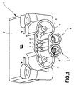
- the pin contact plug 1 shown in FIG. 1 essentially comprises a housing 2 with a connecting apron 3, which essentially surrounds the electrical mating face. Within the connection apron 3 are the two main pin contacts 4, the four pilot pin contacts 5 and a coding pin 6 are arranged. The coding pin 6 is used for voltage coding and to differentiate between wet, dry and other loading systems.
- apron 3 a fluid can 7 and a fluid can in the housing 2 8 arranged.
- the fluid can 8 serves for the passage of air and the fluid can 7 for Passing through battery fluid or distilled water, which is why you use a Valve system is provided.
- the fluid can 8 could be with the same valve system be equipped. However, this is not necessarily due to the harmless medium air required.
- the fluid boxes 7 and 8 are in a common housing area 9 housed. Only the fluid can 7 will be described in detail below. This differs from the fluid can 8 by its valve system. Due to the Alignment of components, the valve box 8 is identical with respect to the rest of the structure to the fluid can 7.
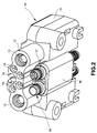
- the pin contact plug 1 from FIG. 1 can be connected to a socket contact socket from FIG. 2 put on.
- the socket contact socket 10 comprises a housing 11, one arranged thereon and can be plugged into the terminal apron 3 in a substantially precise fit Plug section 12.
- the plug section 12 are the main socket contacts 13 and the four pilot socket contacts 14 are arranged.
- the one also arranged in the plug section 12 Coding pin 15 is with coding pin 6 of the associated pin contact plug 1 pluggable.
- a housing area 16 is arranged under the plug section 12, in which two are parallel mutually arranged fluid plugs 17 and 18 are arranged.
- the fluid connector 18 can be plugged into the fluid socket 8 and, like this, has no valve system.
- the fluid plug 17 has a valve system similar to the fluid socket 7 and is suitable for the passage of battery fluid and with the fluid can 7 pluggable. Except for the valve system, the fluid connector 18 is identical to the fluid connector 17 built.
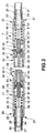
- a cylindrical bore 19 is arranged in the housing region 9 of the fluid can 7, which runs parallel to the pin contacts 4 and 5.
- a connector plug 21 firmly pressed in the rear end 20 of the through hole 19 .
- the connector plug 21 corresponding fir tree profiles 22, which are in the inner wall the through hole 19 claw.
- the plug 21 has one Flange 23, which acts as a stop at the rear end 20 of the housing region 9 serves. This is followed by another fir tree profiling 24 on the outside, onto which the end of a hose 25 is firmly pushed.
- the plug 21 has a through hole 26 to the corresponding supply line, which is connected to the flow channel 27 of the hose 25 is connected.
- the housing area 16 of the fluid connector 17 also has a cylindrical through hole 29 which have the same diameter as the through hole 19 the fluid can has 7.
- a plug 21 inserted In the rear end 28 of the through hole 29 is a plug 21 inserted, which is identical to the plug 21 of the fluid socket 7 is designed, which is why reference is made to these components with the same reference numerals becomes.
- the socket 32 has a hollow cylindrical overlapping area 33 with a plug opening 34 and a valve seat region 35 arranged in the through bore 19.
- a Constriction in the plug-in receptacle 32 which is not described in any more detail, is used for receiving of the collar 31.
- In the valve seat area 35 is a valve seat 36 with a frustoconical shape Surface molded.
- the valve seat 36 is coaxial with the axis A of the fluid can 7 arranged.
- the large diameter of the valve seat 36 opens to the through hole 19 and the small diameter of the valve seat 36 goes into the, in cross section circular passage 37 over.
- the passage 37 is with the plug opening 34 in connection.
- the insertion element 40 has a plug-in area 41 which can be plugged into the plug-in opening 34.
- the plug element 40 made of an elastomer material and Plug-in area 41 additionally has sealing beads 42 for pressing against the inner surface of the Plug opening 34 on.
- a valve seat area 43 has a, a cone-shaped inner surface having valve seat 44 and arranged in the through hole 29.
- the valve seat 44 is arranged coaxially to the main axis B of the fluid connector 17. The large diameter of the valve seat 44 points in the direction of the passage 29 and its small diameter goes into a circular cross section Passage 45 over.
- the passage 45 extends from the valve seat 44 to the end of the plug-in area 41.
- a compression spring 47 is supported on the front side 46 of the connecting plug 21 from, which is arranged coaxially to the axes A and B.
- the compression spring 47 presses one Valve tappet 48 in its closed position, so that a sealing area 49 seals comes with the valve seat 36 or 44 to the system.
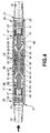
- the valve lifter 48 has a pin region extending to the rear 50 on the axially spaced guide webs 51 are arranged. Each three guide webs 51 are arranged in one plane and form a wreath.
- the guide webs 51 of the two guide rings are in the essentially arranged in a row in order to minimize flow resistance to build.
- the compression spring is supported on the first guide ring 47 from.
- the guide webs 51 of a guide ring define an outer diameter, which is slightly smaller than the inside diameter of the through hole 19 or 29, so that the valve lifter 48 does not tip over in the respective through hole 19 or 29 is guided or centered.
- the pin section 50 closes with a cone-shaped outer surface provided sealing area 49.
- Sealing area 49 has a plurality of stepped O-ring seats 52 on which O-rings of different diameters can be arranged.
- the O-ring seats 56 and the associated O-rings are dimensionally arranged so that they are as possible rest evenly on valve seat 36 or 44.
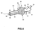
- the small diameter of the sealing area 49 includes a cylindrical extension designed as an actuating plunger 53, which in the exemplary embodiment shown in FIG. 5 has a cross slot 54, so that its cross-section is divided into four quarter-circle sections.
- the O-rings 55 are spaced as evenly as possible from one another on the O-ring seats 52 arranged.
- the cross slot 54 forms four channels 56 in the extension 53 have a certain width and length.
- a gap 57 which is essentially cylindrical in cross section is and has a certain length and width. The gap 57 opens into the Plug-in opening 34, into which the extension 53 in the fluid box 7 also extends (see Fig. 8).
- the extension 53 extends almost to the end of the plug element 40.
- the extension 53 has those formed by the cross slot 54 Channels 56 of a certain width and length on between the passage 45 and the extension 53 a cylindrical ring-shaped gap 58 is formed, which a certain Has length and width.
- both the channels 56 and the columns 57 and 58 should be dimensioned in this way be that, depending on the liquid to be passed through (usually distilled Water) a residual liquid retaining capillary action when closed Valve system is present.
- the pin contact plug 1 shown in Fig. 1 is preferably located on a charger for charging traction batteries.
- wet batteries or other technologies
- the pin contact plug 1 is coupled to a socket contact socket 10 of a battery.
- the Main contacts 4 and 13 and the pilot contacts 5 and 14 in contact with each other. This is only possible if the coding pins 6 and 15 can be plugged.
- the plug elements 40 of the socket contact socket 10 are inserted into the plug receptacles 32 of the pin contact plug 1 introduced.
- the sealing beads 42 thus take place a tight connection between the fluid connector 17 and the fluid socket 7. The same applies for guiding the air through the fluid socket 8 and the fluid plug 18.
- the length and width of the column 57 and channels 56 must be chosen be that the largest possible flow cross-section is provided; however yourself nevertheless the positive capillary effect which retains residual liquid when separating Sets fluid connector 17 and fluid socket 7.
- the flow cross section is preferably in the area of the passages 37 and 45 at least 40% of the flow cross section of the Supply hose 25. This guarantees optimal water flow.
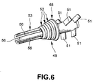
- valve lifter 48 Another variant of a valve lifter 48 is shown in FIG. 6. As far as it is are identical elements to the previous embodiment, is on this with The same reference numbers are referred to and reference is made to the above description.
- the extension 53 also has an essentially circular basic cross section in which three channels 56 are formed. Two of these channels 56 run parallel to each other and point with their opening in the same direction. The third channel 56 is arranged on the opposite side of the extension 53 and extends midway between the other two channels 56, with its opening in the opposite Direction points. As a result, the extension 53 receives a W-shaped one in principle Cross-section. This cross section is extremely stable and not as flexible as the one above described cross section of the extension 53. The length and width of the channels 56 is again chosen so that the desired in the closed state of the valve systems Capillary action restraining residual liquid.
Landscapes
- Chemical & Material Sciences (AREA)
- Chemical Kinetics & Catalysis (AREA)
- Electrochemistry (AREA)
- General Chemical & Material Sciences (AREA)
- Quick-Acting Or Multi-Walled Pipe Joints (AREA)
- Infusion, Injection, And Reservoir Apparatuses (AREA)
Abstract
Description
- Fig. 1
- eine perspektivische Darstellung einer Stiftkontaktdose eines kombinierten Lade- und Fluidsteckverbinders,
- Fig. 2
- eine perspektivische Darstellung eines Buchsenkontaktsteckers eines kombinierten Lade- und Fluidsteckverbinders,
- Fig. 3
- eine Querschnittsdarstellung eines Fluidsteck-Systems in ungestecktem Zustand,
- Fig. 4
- das Fluidsteck-System aus Fig. 3 im gesteckten Zustand,
- Fig. 5
- eine perspektivische Darstellung einer ersten Ausführungsform eines Ventilstößels,
- Fig. 6
- eine perspektivische Darstellung einer zweiten Ausführungsform eines Ventilstößels,
- Fig. 7
- eine vergrößerte Querschnittsdarstellung des Übersteckungs- und Ventilsitzbereichs des Fluidsteckers und
- Fig. 8
- eine vergrößerte Querschnittsdarstellung des Übersteckungs- und Ventilsitzbereichs der Fluiddose.
Claims (20)
- Kombinierter Lade- und Fluidsteckverbinder mit mindestens einem Fluidstecksystem, das ein Fluidstecker (17) und eine mit diesem steckbare Fluiddose (7) umfaßt, dadurch gekennzeichnet, daß der Fluidstecker (17) und die Fluiddose (7) jeweils einen im Strömungspfad (19, 29) angeordneten Ventilstößel (48) aufweisen, der jeweils mittels einer Federeinrichtung (47) in Richtung eines im Strömungspfad (19, 29) angeordneten, eine Durchlaßöffnung umgebenden Ventilsitzes (36, 44) vorgespannt ist und dessen Dichtabschnitt (49) im ungesteckten Zustand von Fluidstecker (17) und Fluiddose (7) auf dem Ventilsitz (36, 44) zum Schließen der Durchlaßöffnung dichtend aufsitzt, daß jeder Ventilstößel (48) einen als Betätigungsstößel ausgebildeten Fortsatz (53) aufweist, der jeweils in einen Übersteckungsbereich (33, 41) des Fluidsteckers (17) und der Fluiddose (7) derart hineinragt, daß im gesteckten Zustand von Fluidstecker (17) und Fluiddose (7) der Fortsatz (53) des Fluidsteckers (17) von einem Anschlag der Fluiddose (7) und der Fortsatz (53) der Fluiddose (7) von einem Anschlag des Fluidsteckers (17) mit einer Verschiebekraft entgegen der Wirkung der zugehörigen Federeinrichtung zum Öffnen der jeweiligen Durchlaßöffnung verschoben ist, wobei die Fortsätze (53) zumindest abschnittsweise in einem zum Strömungspfad gehörenden Durchgang (37, 45) angeordnet sind und der Spalt (57, 58) zwischen einer Außenoberfläche des Fortsatzes (53) und der Innenfläche des Durchgangs (37, 45) eine Länge und Breite derart aufweist, daß sich zumindest im ungesteckten Zustand von Fluidstecker (17) und Fluiddose (7) im Spalt (57, 58) eine, eine Restflüssigkeit bindende Kapillarwirkung einstellt.
- Steckverbinder nach Anspruch 1, dadurch gekennzeichnet, daß der Ventilstößel (48) und der Fortsatz (53) koaxial zueinander angeordnet sind, und daß die Anschläge für die Fortsätze (53) im Fluidstecker (17) oder in der Fluiddose (7) jeweils von einer Stirnseite des jeweils zugeordneten Fortsatzes (53) des übersteckbaren Fluidsteckers (17) oder der Fluiddose (79) gebildet sind.
- Steckverbinder nach Anspruch 1 oder 2, dadurch gekennzeichnet, daß der Fortsatz (53) im wesentlichen aus einem zylindrischen Grundkörper gebildet ist und die Innenfläche des Durchgangs (37, 45) im Fluidstecker (17) oder in der Fluiddose (7) im wesentlichen als eine zylindrische Mantelfläche ausgestaltet ist.
- Steckverbinder nach einem der Ansprüche 1 bis 3, dadurch gekennzeichnet, daß der Spalt (57, 58) eine mittlere Breite von 0,1 mm bis 1 mm, bevorzugt 0,6 mm, aufweist.
- Steckverbinder nach einem der Ansprüche 1 bis 4, dadurch gekennzeichnet, daß die Länge des Spaltes (57, 58) mindestens 4 mm beträgt.
- Steckverbinder nach einem der Ansprüche 1 bis 5, dadurch gekennzeichnet, daß in dem Fortsatz (53) mindestens ein sich längs erstreckender Kanal (56) angeordnet ist, dessen Breite und Länge derart gewählt ist, daß sich zumindest im ungesteckten Zustand von Fluidstecker (17) und Fluiddose (7) im Kanal (56) eine, eine Restflüssigkeit bindende Kapillarwirkung einstellt.
- Steckverbinder nach Anspruch 6, dadurch gekennzeichnet, daß der Kanal (56) eine Breite von 0,1 mm bis 1 mm, bevorzugt 0,6 mm, und eine Länge von mindestens 4 mm aufweist.
- Steckverbinder nach Anspruch 6 oder 7, dadurch gekennzeichnet, daß der Fortsatz (53) drei Kanäle (56) aufweist, die derart versetzt zueinander angeordnet sind, daß der Fortsatz (53) einen im wesentlichen W-förmigen Querschnitt aufweist.
- Steckverbinder nach Anspruch 6 oder 7, dadurch gekennzeichnet, daß der Fortsatz (53) zum Bilden der Kanäle (56) kreuzförmig längs geschlitzt ist.
- Steckverbinder nach einem der Ansprüche 6 bis 9, dadurch gekennzeichnet, daß der mindestens eine Kanal (56) sich in Richtung seiner Tiefe in seiner Breite verengt.
- Steckverbinder nach einem der Ansprüche 6 bis 10, dadurch gekennzeichnet, daß der mindestens eine Kanal (56) sich in Richtung auf den Dichtabschnitt (49) am Ventilstößel (48) zu in seiner Breite verengt.
- Steckverbinder nach einem der Ansprüche 6 bis 11, dadurch gekennzeichnet, daß der Gesamtquerschnitt des Spaltes (57, 58) und des mindestens einen Kanals (56) mindestens 30% des fiktiven Grundkörper-Querschnitts des Fortsatzes (53) beträgt.
- Steckverbinder nach einem der Ansprüche 6 bis 12, dadurch gekennzeichnet, der Fluidstecker (17) oder die Fluiddose (7) mit einem Zuleitungs- bzw. Abführschlauch (25) verbunden sind, wobei der Gesamtquerschnitt des Spaltes (57,58) und des mindestens einen Kanals (56) mindestens 30%, bevorzugt 40% des Durchlaßquerschnitts des Zuleitungs- bzw. Abführschlauchs (25) beträgt.
- Steckverbinder nach einem der Ansprüche 1 bis 13, dadurch gekennzeichnet, daß der Ventilsitz (36, 44) im wesentlichen kegelmantelförmig ausgestaltet ist und der Dichtabschnitt (49) des Ventilstößels (48) eine daran angepaßte Kontur aufweist.
- Steckverbinder nach einem der Ansprüche 14, dadurch gekennzeichnet, daß der Dichtabschnitt (49) als gestufte Kegelstumpfkontur am Ventilstößel (48) ausgestaltet ist, wobei zumindest eine Stufe als Dichtungsringsitz (52) ausgebildet ist, und daß mindestens ein Dichtring (55) auf dem Dichtungsringsitz (52) angeordnet ist und mit dem Ventilsitz (36, 44) in Anlage bringbar ist.
- Steckverbinder nach einem der Ansprüche 6 bis 11, dadurch gekennzeichnet, daß der Dichtabschnitt (49) am Ventilstößel (48) von einem mit einer kegelstumpfförmigen Mantelfläche versehenen, elastischen Dichtkörper gebildet ist.
- Steckverbinder nach einem der Ansprüche 1 bis 16, dadurch gekennzeichnet, daß der Ventilsitz (36, 44), der Durchgang (37, 45) und der Übersteckungsbereich (33, 41) des Fluidsteckers (17) und der Fluiddose (7) von einem einstückig hergestellten Elastomerelement (32, 40) geformt sind.
- Steckverbinder nach einem der Ansprüche 1 bis 17, dadurch gekennzeichnet, daß die Federeinrichtung eine koaxial zum Ventilstößel (48) angeordnete Druckfeder (47) ist, die auf der dem Fortsatz (53) abgewandten Seite des Ventilstößels (48) auf diese eine Kraft ausübt.
- Steckverbinder nach einem der Ansprüche 1 bis 18, dadurch gekennzeichnet, daß der Ventilstößel (48) auf der dem Fortsatz (53) abgewandten Seite einen Stiftabschnitt (50) mit radial abstehenden Führungsstegen (51) aufweist, wobei die Führungsstege (51) den Ventilstößel (48) axial im Strömungspfad (19, 29) führen, und daß die Federeinrichtung sich an der Seitenflanke zumindest eines Führungsstegs (51) abstützt.
- Steckverbinder nach einem der Ansprüche 1 bis 19, dadurch gekennzeichnet, daß der Ventilsitz (36, 44), der Ventilstößel (48) und die Federeinrichtung (47) koaxial in einem gemeinsamen rohrförmigen Gehäuse (9,16) des Fluidsteckers (17) oder der Fluiddose (7) angeordnet sind, wobei an einem Ende des Gehäuses (9, 16) der Übersteckungsbereich (33, 41) und an dem anderen Ende der Zuleitungs- bzw. Abführschlauch (25) angeordnet ist.
Applications Claiming Priority (2)
| Application Number | Priority Date | Filing Date | Title |
|---|---|---|---|
| DE29820933U | 1998-11-23 | ||
| DE29820933U DE29820933U1 (de) | 1998-11-23 | 1998-11-23 | Kombinierter Lade- und Fluidsteckverbinder |
Publications (3)
| Publication Number | Publication Date |
|---|---|
| EP1011159A2 true EP1011159A2 (de) | 2000-06-21 |
| EP1011159A3 EP1011159A3 (de) | 2001-02-07 |
| EP1011159B1 EP1011159B1 (de) | 2004-10-27 |
Family
ID=8065719
Family Applications (1)
| Application Number | Title | Priority Date | Filing Date |
|---|---|---|---|
| EP19990115414 Expired - Lifetime EP1011159B1 (de) | 1998-11-23 | 1999-08-04 | Kombinierter Lade- und Fluidsteckverbinder |
Country Status (2)
| Country | Link |
|---|---|
| EP (1) | EP1011159B1 (de) |
| DE (2) | DE29820933U1 (de) |
Cited By (4)
| Publication number | Priority date | Publication date | Assignee | Title |
|---|---|---|---|---|
| DE102004013090B3 (de) * | 2004-03-17 | 2005-09-01 | Schaltbau Gmbh | Ladesteckverbinderbausatz mit seitlichen Fluidkanälen |
| CN109599693A (zh) * | 2017-09-30 | 2019-04-09 | 比亚迪股份有限公司 | 第一、第二充电连接件以及充电枪、车辆和充电系统 |
| CN113383466A (zh) * | 2019-02-12 | 2021-09-10 | 雷马利普兰特有限及两合公司 | 电插接连接器 |
| CN117212575A (zh) * | 2023-09-19 | 2023-12-12 | 天津鹏翎集团股份有限公司 | 管路组件及管路组件安装方法 |
Families Citing this family (4)
| Publication number | Priority date | Publication date | Assignee | Title |
|---|---|---|---|---|
| FR2915788B1 (fr) | 2007-05-04 | 2012-05-25 | Airbus France | Dispositif de connexion multi-systemes a bord d'un aeronef |
| DE202007007927U1 (de) | 2007-06-05 | 2007-08-23 | Bürkert Werke GmbH & Co. KG | Hybrides Universalverteilersystem mit elektrischen, fluidischen und Kommunikationsfunktionen |
| DE102007062368A1 (de) * | 2007-06-29 | 2009-01-02 | Braun Gmbh | Ventilkopplung |
| CN109944997A (zh) * | 2017-12-21 | 2019-06-28 | 中航光电科技股份有限公司 | 混装连接器及其插头、插座 |
Family Cites Families (3)
| Publication number | Priority date | Publication date | Assignee | Title |
|---|---|---|---|---|
| FR2578950B1 (fr) * | 1985-03-18 | 1988-01-15 | Socapex | Connecteur fluidique miniature |
| DE9305756U1 (de) * | 1993-04-16 | 1994-08-25 | Schaltbau AG, 81677 München | Kombinierte Lade- und Fluidsteckvorrichtung |
| DE19535102C1 (de) * | 1995-09-21 | 1997-04-17 | Dunkel Otto Gmbh | Andockvorrichtung für an ein Fahrzeug mit Elektroantrieb anzuschließende Batterien |
-
1998
- 1998-11-23 DE DE29820933U patent/DE29820933U1/de not_active Expired - Lifetime
-
1999
- 1999-08-04 DE DE59910941T patent/DE59910941D1/de not_active Expired - Lifetime
- 1999-08-04 EP EP19990115414 patent/EP1011159B1/de not_active Expired - Lifetime
Cited By (5)
| Publication number | Priority date | Publication date | Assignee | Title |
|---|---|---|---|---|
| DE102004013090B3 (de) * | 2004-03-17 | 2005-09-01 | Schaltbau Gmbh | Ladesteckverbinderbausatz mit seitlichen Fluidkanälen |
| EP1577969A1 (de) | 2004-03-17 | 2005-09-21 | Schaltbau GmbH | Ladesteckverbindersatz mit seitlichen Fluidkanälen |
| CN109599693A (zh) * | 2017-09-30 | 2019-04-09 | 比亚迪股份有限公司 | 第一、第二充电连接件以及充电枪、车辆和充电系统 |
| CN113383466A (zh) * | 2019-02-12 | 2021-09-10 | 雷马利普兰特有限及两合公司 | 电插接连接器 |
| CN117212575A (zh) * | 2023-09-19 | 2023-12-12 | 天津鹏翎集团股份有限公司 | 管路组件及管路组件安装方法 |
Also Published As
| Publication number | Publication date |
|---|---|
| EP1011159A3 (de) | 2001-02-07 |
| EP1011159B1 (de) | 2004-10-27 |
| DE29820933U1 (de) | 2000-03-30 |
| DE59910941D1 (de) | 2004-12-02 |
Similar Documents
| Publication | Publication Date | Title |
|---|---|---|
| EP0381069B1 (de) | Kupplungsmuffe für hydraulische Leitungsverbindung | |
| DE2626954C2 (de) | Steuerschieberanordnung für eine durch Druckluft angetriebene Hydraulikpumpe | |
| DE1809166C3 (de) | Kupplungseinheit für Strömungssysteme | |
| EP0038056A2 (de) | Schnellkupplung für Schläuche o.dgl. | |
| DE3027827A1 (de) | Steckverbinder fuer lichtwellenleiter | |
| EP1011159B1 (de) | Kombinierter Lade- und Fluidsteckverbinder | |
| EP2050996A1 (de) | Steckbarer und verrastbarer Leitungsverbinder | |
| DE1959737B2 (de) | Kupplung fuer unter hohem druck stehende fluessigkeitsleitun gen | |
| DE3322844A1 (de) | Solenoid-ventil | |
| DE3115908A1 (de) | "brennstoffpumpe" | |
| EP0084182A1 (de) | Kraftstoff-Einspritzdüse für Brennkraftmaschinen | |
| DE20110365U1 (de) | Kupplungsvorrichtung zur Übertragung von Fluiddruck | |
| DE2509679C3 (de) | Steuerventil für die Druckluftbremsanlage eines Zugfahrzeuges | |
| DE20318583U1 (de) | Ladesteckverbindersatz mit Adapter | |
| DE69007000T2 (de) | Dentalgerät im Baukastensystem. | |
| WO1999040352A1 (de) | Schaltelement, insbesondere pneumatikventil | |
| DE4341087C2 (de) | Abgedichtete Schaltvorrichtung | |
| DE19810985C2 (de) | Verfahren und Vorrichtung für die automatisierte Montage von Konus-Halbklemmbacken eines Ventils einer Verbrennungskraftmaschine | |
| WO2015044067A2 (de) | Vorrichtung zur dichtenden durchführung von leitungen durch ein trennelement | |
| DE202007018625U1 (de) | Schneidbrenner mit einem Brennerkopf, der eine auswechselbare Schneiddüse aufnimmt | |
| DE10332332B4 (de) | Automatisch in einem Notfall zu entkoppelnde Strömungsmittelkupplung | |
| DE4426946B4 (de) | Vorrichtung zum Fördern von Kraftstoff aus einem Vorratsbehälter zur Brennkraftmaschine eines Kraftfahrzeugs | |
| DE3005490A1 (de) | Auch unter druck kuppelbare schnellverschlusskupplung | |
| DE4338665A1 (de) | Hydraulik-Steckkupplung | |
| DE3607940C2 (de) | Mehrfach-Leitungskupplung |
Legal Events
| Date | Code | Title | Description |
|---|---|---|---|
| PUAI | Public reference made under article 153(3) epc to a published international application that has entered the european phase |
Free format text: ORIGINAL CODE: 0009012 |
|
| AK | Designated contracting states |
Kind code of ref document: A2 Designated state(s): DE FR GB IT |
|
| AX | Request for extension of the european patent |
Free format text: AL;LT;LV;MK;RO;SI |
|
| PUAL | Search report despatched |
Free format text: ORIGINAL CODE: 0009013 |
|
| RIC1 | Information provided on ipc code assigned before grant |
Free format text: 7H 01M 2/36 A, 7H 01R 13/00 B, 7B 60R 16/04 B |
|
| AK | Designated contracting states |
Kind code of ref document: A3 Designated state(s): AT BE CH CY DE DK ES FI FR GB GR IE IT LI LU MC NL PT SE |
|
| AX | Request for extension of the european patent |
Free format text: AL;LT;LV;MK;RO;SI |
|
| 17P | Request for examination filed |
Effective date: 20010125 |
|
| AKX | Designation fees paid |
Free format text: DE FR GB IT |
|
| GRAP | Despatch of communication of intention to grant a patent |
Free format text: ORIGINAL CODE: EPIDOSNIGR1 |
|
| GRAA | (expected) grant |
Free format text: ORIGINAL CODE: 0009210 |
|
| GRAS | Grant fee paid |
Free format text: ORIGINAL CODE: EPIDOSNIGR3 |
|
| AK | Designated contracting states |
Kind code of ref document: B1 Designated state(s): DE FR GB IT |
|
| REG | Reference to a national code |
Ref country code: GB Ref legal event code: FG4D Free format text: NOT ENGLISH |
|
| REF | Corresponds to: |
Ref document number: 59910941 Country of ref document: DE Date of ref document: 20041202 Kind code of ref document: P |
|
| GBT | Gb: translation of ep patent filed (gb section 77(6)(a)/1977) |
Effective date: 20050125 |
|
| ET | Fr: translation filed | ||
| PLBE | No opposition filed within time limit |
Free format text: ORIGINAL CODE: 0009261 |
|
| STAA | Information on the status of an ep patent application or granted ep patent |
Free format text: STATUS: NO OPPOSITION FILED WITHIN TIME LIMIT |
|
| 26N | No opposition filed |
Effective date: 20050728 |
|
| PGFP | Annual fee paid to national office [announced via postgrant information from national office to epo] |
Ref country code: GB Payment date: 20120823 Year of fee payment: 14 |
|
| PGFP | Annual fee paid to national office [announced via postgrant information from national office to epo] |
Ref country code: FR Payment date: 20120903 Year of fee payment: 14 Ref country code: DE Payment date: 20120830 Year of fee payment: 14 Ref country code: IT Payment date: 20120806 Year of fee payment: 14 |
|
| GBPC | Gb: european patent ceased through non-payment of renewal fee |
Effective date: 20130804 |
|
| PG25 | Lapsed in a contracting state [announced via postgrant information from national office to epo] |
Ref country code: DE Free format text: LAPSE BECAUSE OF NON-PAYMENT OF DUE FEES Effective date: 20140301 |
|
| REG | Reference to a national code |
Ref country code: DE Ref legal event code: R119 Ref document number: 59910941 Country of ref document: DE Effective date: 20140301 |
|
| REG | Reference to a national code |
Ref country code: FR Ref legal event code: ST Effective date: 20140430 |
|
| PG25 | Lapsed in a contracting state [announced via postgrant information from national office to epo] |
Ref country code: IT Free format text: LAPSE BECAUSE OF NON-PAYMENT OF DUE FEES Effective date: 20130804 |
|
| PG25 | Lapsed in a contracting state [announced via postgrant information from national office to epo] |
Ref country code: GB Free format text: LAPSE BECAUSE OF NON-PAYMENT OF DUE FEES Effective date: 20130804 |
|
| PG25 | Lapsed in a contracting state [announced via postgrant information from national office to epo] |
Ref country code: FR Free format text: LAPSE BECAUSE OF NON-PAYMENT OF DUE FEES Effective date: 20130902 |