EP1010786A2 - Vliesleger - Google Patents
Vliesleger Download PDFInfo
- Publication number
- EP1010786A2 EP1010786A2 EP99124703A EP99124703A EP1010786A2 EP 1010786 A2 EP1010786 A2 EP 1010786A2 EP 99124703 A EP99124703 A EP 99124703A EP 99124703 A EP99124703 A EP 99124703A EP 1010786 A2 EP1010786 A2 EP 1010786A2
- Authority
- EP
- European Patent Office
- Prior art keywords
- carriage
- support
- woven layer
- main
- carriages
- Prior art date
- Legal status (The legal status is an assumption and is not a legal conclusion. Google has not performed a legal analysis and makes no representation as to the accuracy of the status listed.)
- Granted
Links
- 239000010410 layer Substances 0.000 description 26
- 235000004443 Ricinus communis Nutrition 0.000 description 2
- 240000000528 Ricinus communis Species 0.000 description 2
- 238000010276 construction Methods 0.000 description 2
- 230000033001 locomotion Effects 0.000 description 2
- 230000001360 synchronised effect Effects 0.000 description 2
- 230000005540 biological transmission Effects 0.000 description 1
- 230000008878 coupling Effects 0.000 description 1
- 238000010168 coupling process Methods 0.000 description 1
- 238000005859 coupling reaction Methods 0.000 description 1
- 230000010354 integration Effects 0.000 description 1
- 238000004519 manufacturing process Methods 0.000 description 1
- 239000002356 single layer Substances 0.000 description 1
Images


Classifications
-
- D—TEXTILES; PAPER
- D01—NATURAL OR MAN-MADE THREADS OR FIBRES; SPINNING
- D01G—PRELIMINARY TREATMENT OF FIBRES, e.g. FOR SPINNING
- D01G25/00—Lap-forming devices not integral with machines specified above
Definitions
- the invention relates to a nonwoven layer, which in particular is suitable for large laying widths, with the features in Preamble of the main claim.
- Such a fleece layer is known from practice. He has two main cars with two endless and on the main car conveyor belts and a Discharge belt. A support carriage is included for the conveyor belts at least one roll to support a horizontal one Conveyor belt runs provided. With the known fleece layer the support carriage is independently movable and is from the upper main car via a cable drive driven. This arrangement is complex.
- the invention solves this problem with the features in the main claim.
- at least one support carriage is rigidly connected to the upper main carriage or superstructure. This has the advantage that the complex cable drive can be dispensed with. The drive transmission is also more direct, precise and less prone to wear.
- the support carriage is in integrated the upper main car. It is for that advantageous if the superstructure on the bottom one Approach to include the support car components. This design is particularly compact and saves space and Construction effort. In addition, this car arrangement can store particularly cheaply in the frame of the fleece layer, lead and drive.
- the support car has several, preferably three in Triangle-shaped pulleys with which the lower Conveyor belt run can be performed so that the belt inlet and the band outlet at substantially the same level lie. This has the advantage that the lower one Conveyor belt run completely parallel to the take-off belt can extend. This provides optimal coverage and a safe protection against wind and other influences for the multi-layer fleece deposited on the take-off belt.
- the fleece layer according to the invention can have one or more have other support cars, on the one hand for the other lower conveyor belt run and possibly also for an upper conveyor belt strand in connection with one there Tensioners are provided. All support cars can be used with the The uppercarriage is in the drive connection.
- FIG. 1 shows a fleece layer (1) in the form of a so-called fleece band layer, which from a card Single-layer pile (3) fed via a feed belt (4) with two revolving endless conveyor belts (7,8) and on a transversely extending discharge belt (5) a multi-layer fleece and in the form of scales discards.
- the arrows (33) indicate the direction of conveyance of the pile (3).
- the fleece layer (1) shown corresponds in its Basic design and non-woven layers known in its kinematics according to EP-A-0 517 563 or WO-A-97/19209.
- the fleece layer (1) has two main carriages (10, 11), which are Move back and forth over the discharge belt (5).
- the embodiment shown is a co-rotating fleece layer (1), in which the main carriage (10,11) always drive in the same direction.
- the Upper carriage (10) moves with half Speed compared to the lower laying carriage (11) and also places half the distance between the reversal points back.
- the two conveyor belts (7,8) are movable Deflection rollers (36) on the two main carriages (10, 11) and via stationary deflection rollers (37) in the frame (2) of the Fleece layer (1) in movable loops.
- the supplied single-ply pile (3) is first on one Conveyor belt (7) open up to a belt inlet (9) on Superstructure (10) transported where the second conveyor belt (8) come in addition.
- the tape inlet (9) can be an open one or closed belt inlet.
- the conveyor belts (7, 8) reappear on the laying carriage (11) apart and extend in on both sides lower horizontal conveyor belt runs (26, 27) across and parallel over the deposited fleece (32) and the discharge belt (5). They act as a cover and can also be opened rest on the fleece (32).
- Figures 2 and 3 show the two end positions of the Carriage movements, the laying carriage (11) in FIG. 2 on the right edge of the discharge belt (5) or Laying width (6) and in figure (3) on the left edge.
- those on the superstructure (10) converging conveyor belts (7,8) from the belt inlet (9) in a substantially horizontal band section directly led to the laying car (11).
- Such a design is e.g. known from EP 0 315 930.
- the two conveyor belts running in parallel become casual (7,8) between uppercarriage (10) and laying carriage (11) over a stationary deflection roller arrangement (37) in the frame (2) guided.
- the fleece layer (1) shown can be a so-called Paper felt storage, which is for particularly large laying widths (6) is suitable. At least there is support for this the lower conveyor belt dreams (26,27) advantageous. A Such support can also be found in nonwoven layers successfully used with a smaller laying width.
- the Support consists of at least one auxiliary car (12, 13), which can be moved back and forth over the discharge belt (5) is stored.
- FIG. 4 shows this Arrangement.
- One support carriage (12) is freely movable stored and is in a drive connection (28) the uppercarriage (10).
- the drive connection (28) is off Figure 5 can be seen.
- Figure 4 shows the same Carriage position to guide the conveyor belts (7,8).
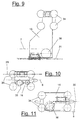
- the coupled support carriage (13) is on a lower approach (25) of the superstructure (10) arranged. Due to its structural Integration does not have its own castors (34).
- the rigid coupling or the drive connection (28) e.g. from one over fixed castors circulating rope drive can exist, the move two support carriages (12, 13) synchronized with the superstructure (10) with the same direction and speed.
- the coupled support car (13) independently movable on the Carriage guide (18) or other suitable location be stored. He is then through with the uppercarriage (10) rigidly connected to a rod or the like.
- Figures 2 and 3 illustrate the positions of the support car (12.13). If the laying carriage (11) is in a narrow position Neighborhood to the uppercarriage (10) on the right edge of the Laying width (6), the free support carriage (12) a position in about half of the laying width which he the long spread conveyor belt strand (26) between Laying carriage (11) and the left frame (2) approximately in the middle supported. Figure 2 shows this arrangement. In the other The laying carriage is in the extreme position according to FIG (11) and the support carriage (12) side by side on the other edge the laying width (6). The superstructure (10) with its The tensioning carriage (13) then takes a position approximately in the middle Insert width (6) and then support it after the right side spread out lower conveyor belt strand (27) between the laying carriage (11) and the right frame (2).
- the belt guide of the conveyor belt dreams (26, 27) on the two Support carriage (12, 13) is preferably of the same design. In a modified embodiment, it can also vary. In the embodiment shown there are the inlet (23) and the outlet (24) for the Conveyor belt dreams (26, 27) each at the same level.
- the support car (12, 13) has one Omega guide (19) for the conveyor belt dreams (26, 27). she e.g. from three pulleys (20,21,22), the parallel to each other and with their axes in a triangle are arranged.
- the conveyor belt dreams (26,27) are under the two outer pulleys (20,22) and inside in a raised loop over the middle pulley (21) performed. With this omega guide (19), too Maintain tape tension in an advantageous manner.
- more than three pulleys can be arranged.
- the lower tensioning carriage (15) is on one, for example upper carriage guide (17) by means of rollers (34) movably supported and has a protruding downward Housing part. His deflection roller (38) is thereby in the area above the laying carriage (11) and support carriage (12) as well as below the top edge and the tape inlet (9) of the superstructure (10).
- the lower tension carriage (15) can thereby according to Figure 3 above the laying carriage (11) and move the support carriage (12) and its tension loop to extend to the uppercarriage (10).
- the lower tensioning carriage (15) is in one Drive connection (31) with the superstructure (10) and moved back and forth synchronously with this. His route corresponds to half the laying width (6).
- Figure 5 illustrates this drive relationship.
- a circulating rope drive In the embodiment shown there is a circulating rope drive.
- it can alternatively an independent drive act from the superstructure (10) or the Machine control is controlled.
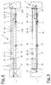
- the other upper tension carriage (14) is also over Rollers (34) on the upper carriage guide (17) movably supported. He is next to with a side distance the lower tension carriage (15) arranged and moves in the same direction with this.
- the upper tension carriage (14) is standing in a drive connection (30) to the laying carriage (11) and is moved back and forth synchronously with it.
- the upper support carriage (16) is also by means of rollers (34) movably mounted on the upper carriage guide (17). It has a support roller (35) over which the upper run the conveyor belt (8) is guided and supported.
- the Support carriage (16) moves between the upper tension carriage (14) and the right frame (2) back and forth and stands in a drive connection (29) with the superstructure (10). This drive connection (29) can be the same as in the others Cases.
- the upper support carriage (16) and the Upper wagons (14) can be above the other main and Move the auxiliary carriage (10, 11, 12, 13).
- the driving length of the the upper wagon (14) corresponds to the full laying width (6) and the travel path of the upper support carriage (16) half Laying width (6).
- the lower conveyor belt run (27) is from the laying carriage (11) over the lower tensioning carriage (13) into the right frame (2) guided, deflected upwards and over the support carriage (16) led to the tensioning carriage (14).
- the upper tension carriage (14) pulls his tension loop with a distance over the superstructure (10) and over the other conveyor belt (7).
- In the right Frame (2) is also a clamping device for Tightening the conveyor belt (8) arranged.
- FIGS. 2 and 3 show the positions of the tensioning carriages (14, 15) and the support carriage (16) in the two outer Laying carriage positions. If the laying carriage (11) on right edge of the laying width (6) are the two Spannwagen (14,15) in a relatively close neighborhood on opposite left edge of the laying width (6) positioned.
- the support carriage (16) is located approximately in the middle between the upper tensioning carriage (14) and the right frame (2). According to the other edge position Figure 3 is the lower tensioning carriage (15) approximately in the middle the laying width (6) positioned while the upper Spannwagen (14) and the support carriage (16) in a relatively narrow Neighborhood to each other and close to the right frame (2) are located.
- the carriage guidance (17, 18) can e.g. Guide rails or - be pipes that run across the discharge belt (5) extend between the side frame parts (2). she are in pairs and to the side of the conveyor belts (7,8) arranged.
- the upper and lower carriage guides (17, 18) are parallel and spaced one above the other.
- FIG possible in different ways they can Support car (12,13,16) in number, arrangement and Drive types vary.
- the Auxiliary car (12,13,14,15,16) also a belt or Have chain drive.
- the tensioning carriage (14, 15) can be omitted.
- a modified embodiment can also only with one Tension wagons get along.
- the two Main carriage (10.11) through programmable drives that e.g. are equipped with synchronous motors. Through an appropriate program or Computer control can move the car Manufacture of different fleece thicknesses or warping over the laying width (6) varies become.
Landscapes
- Engineering & Computer Science (AREA)
- Textile Engineering (AREA)
- Preliminary Treatment Of Fibers (AREA)
- Treatment Of Fiber Materials (AREA)
- Folding Of Thin Sheet-Like Materials, Special Discharging Devices, And Others (AREA)
- Nonwoven Fabrics (AREA)
Abstract
Description
Beim erfindungsgemäßen Vliesleger ist zumindest der eine Stützwagen starr mit dem oberen Hauptwagen oder Oberwagen verbunden. Dies hat den Vorteil, daß der bauaufwendige Seiltrieb entfallen kann. Außerdem ist die Antriebsübertragung direkter, präziser und weniger verschleißanfällig.
- Figur 1:
- eine perspektivische Übersichtsdarstellung für einen Vliesleger mit zwei Stützwagen,
- Figuren 2 und 3:
- zwei Seitenansichten des Vlieslegers in zwei Betriebsstellungen,
- Figur 4:
- eine Seitenansicht des Vlieslegers mit einer Darstellung der Führung der beiden Förderbänder,
- Figur 5:
- eine Seitenansicht des Vlieslegers von Figur 4 mit einer Darstellung der Antriebsverbindungen der Stütz- und Spannwagen zu den beiden Hauptwagen,
- Figur 6:
- eine vergrößerte Seitenansicht des unteren Hauptwagens oder Legewagens,
- Figur 7:
- eine vergrößerte Seitenansicht des oberen Hauptwagens oder Oberwagens mit einem integrierten Stützwagen,
- Figur 8:
- eine vergrößerte Seitenansicht eines weiteren Stützwagens,
- Figur 9:
- eine vergrößerte Seitenansicht eines oberen Spannwagens,
- Figur 10:
- eine vergrößerte Seitenansicht eines oberen Stützwagens und
- Figur 11:
- eine vergrößerte Seitenansicht eines oberen Spannwagens.
- 1
- Vliesleger
- 2
- Gestell
- 3
- Flor
- 4
- Zuführband
- 5
- Abführband
- 6
- Legebreite
- 7
- Förderband
- 8
- Förderband
- 9
- Bandeinlauf
- 10
- Oberwagen, Hauptwagen
- 11
- Legewagen, Hauptwagen
- 12
- Stützwagen, Hilfswagen, frei
- 13
- Stützwagen, Hilfswagen, gekoppelt
- 14
- Spannwagen, Hilfswagen, oben
- 15
- Spannwagen, Hilfswagen, unten
- 16
- Stützwagen, oben
- 17
- Wagenführung, oben
- 18
- Wagenführung, unten
- 19
- Omega-Führung
- 20
- Umlenkrolle
- 21
- Umlenkrolle
- 22
- Umlenkrolle
- 23
- Einlaß
- 24
- Auslaß
- 25
- Ansatz
- 26
- unteres Förderbandtrum, Abdeckung
- 27
- unteres Förderbandtrum, Abdeckung
- 28
- Antriebsverbindung Stützwagen, unten
- 29
- Antriebsverbindung Stützwagen, oben
- 30
- Antriebsverbindung Spannwagen, oben
- 31
- Antriebsverbindung Spannwagen, unten
- 32
- Vlies
- 33
- Förderrichtung
- 34
- Laufrolle
- 35
- Stützrolle
- 36
- Umlenkrolle, Hauptwagen
- 37
- Umlenkrolle, Gestell
- 38
- Umlenkrolle, Spannwagen
Claims (12)
- Vliesleger, insbesondere für große Legebreiten, mit einem Abführband (5), mehreren Hauptwagen (10,11) und zwei endlos umlaufenden und über die Hauptwagen (10,11) geführten Förderbändern (7,8), wobei mindestens ein Stützwagen (12,13,16) mit mindestens einer Rolle zur Stützung eines Förderbandtrums (26,27) vorgesehen ist, dadurch gekennzeichnet, daß ein Stützwagen (13) starr mit dem oberen Hauptwagen (10) verbunden ist.
- Vliesleger nach Anspruch 1, dadurch gekennzeichnet, daß der Stützwagen (13) in den oberen Hauptwagen (10) integriert ist.
- Vliesleger nach Anspruch 1 oder 2, dadurch gekennzeichnet, daß der Stützwagen (13) an einem nach unten ragenden Ansatz (25) des oberen Hauptwagens (10) angeordnet ist.
- Vliesleger nach Anspruch 1, 2 oder 3, dadurch gekennzeichnet, daß die beiden Hauptwagen (10,11) nebeneinander auf einer Wagenführung (17) gelagert sind.
- Vliesleger nach einem der Ansprüche 1 bis 4, dadurch gekennzeichnet, daß am Stützwagen (12,13) mehrere Umlenkrollen (20,21,22) für das Förderbandtrum (26,27) angeordnet sind, wobei der Bandeinlaß (23) und der Bandauslaß (24) im wesentlichen auf gleicher Höhe liegen.
- Vliesleger nach Anspruch 5, dadurch gekennzeichnet, daß mindestens drei Umlenkrollen (20,21,22) mit ihren Achsen im Dreieck oder Mehreck angeordnet sind und im wesentlichen eine Omega-Führung (19) für das Förderbandtrum (26,27) bilden.
- Vliesleger nach einem der Ansprüche 1 bis 6, dadurch gekennzeichnet, daß der Vliesleger (1) zwei Stützwagen (12,13) aufweist, die jeweils einem unteren Bandtrum (26,27) der beiden Förderbänder (7,8) zugeordnet sind.
- Vliesleger nach einem der Ansprüche 1 bis 7, dadurch gekennzeichnet, daß der Vliesleger (1) mindestens einen eigenständig verfahrbar gelagerten Stützwagen (12) aufweist, der neben dem unteren Hauptwagen (11) angeordnet ist und in Antriebsverbindung (28) mit dem oberen Hauptwagen (10) steht.
- Vliesleger nach einem der Ansprüche 1 bis 8, dadurch gekennzeichnet, daß der Vliesleger (1) mindestens einen verfahrbar gelagerten Spannwagen (14,15) für mindestens ein Förderband (7,8) aufweist.
- Vliesleger nach Anspruch 9, dadurch gekennzeichnet, daß der oder die Spannwagen (14,15) in Antriebsverbindung mit mindestens einem der Hauptwagen (10,11) stehen.
- Vliesleger nach einem der Ansprüche 1 bis 10, dadurch gekennzeichnet, daß der Vliesleger (1) mindestens einen weiteren eigenständig verfahrbar gelagerten Stützwagen (16) aufweist, der einem Spannwagen (14) zugeordnet ist.
- Vliesleger nach Anspruch 11, dadurch gekennzeichnet, daß der weiterer Stützwagen (16) in Antriebsverbindung mit einem Hauptwagen (10,11) steht.
Applications Claiming Priority (2)
| Application Number | Priority Date | Filing Date | Title |
|---|---|---|---|
| DE29822460U | 1998-12-18 | ||
| DE29822460U DE29822460U1 (de) | 1998-12-18 | 1998-12-18 | Vliesleger |
Publications (3)
| Publication Number | Publication Date |
|---|---|
| EP1010786A2 true EP1010786A2 (de) | 2000-06-21 |
| EP1010786A3 EP1010786A3 (de) | 2001-03-07 |
| EP1010786B1 EP1010786B1 (de) | 2003-09-24 |
Family
ID=8066756
Family Applications (1)
| Application Number | Title | Priority Date | Filing Date |
|---|---|---|---|
| EP99124703A Expired - Lifetime EP1010786B1 (de) | 1998-12-18 | 1999-12-11 | Vliesleger |
Country Status (3)
| Country | Link |
|---|---|
| EP (1) | EP1010786B1 (de) |
| DE (2) | DE29822460U1 (de) |
| ES (1) | ES2207107T3 (de) |
Cited By (3)
| Publication number | Priority date | Publication date | Assignee | Title |
|---|---|---|---|---|
| EP2157216A1 (de) * | 2008-08-21 | 2010-02-24 | Oskar Dilo Maschinenfabrik KG | Vorrichtung zum Legen eines Vlieses |
| DE202012102597U1 (de) | 2012-07-13 | 2013-10-14 | Hi Tech Textile Holding Gmbh | Vliesleger |
| WO2015067704A1 (de) * | 2013-11-08 | 2015-05-14 | Autefa Solutions Germany Gmbh | Vliesleger und betriebsverfahren |
Families Citing this family (3)
| Publication number | Priority date | Publication date | Assignee | Title |
|---|---|---|---|---|
| DE20211365U1 (de) * | 2002-07-27 | 2003-10-09 | AUTEFA Automation GmbH, 86316 Friedberg | Vorrichtung zur Faserbehandlung |
| EP1816243B1 (de) | 2006-02-01 | 2008-06-18 | Oskar Dilo Maschinenfabrik KG | Vorrichtung zum Legen eines Vlieses |
| DE502007003464D1 (de) | 2007-02-15 | 2010-05-27 | Dilo Kg Maschf Oskar | Vorrichtung zum Legen eines Vlieses |
Family Cites Families (10)
| Publication number | Priority date | Publication date | Assignee | Title |
|---|---|---|---|---|
| DE2654860C2 (de) * | 1976-12-03 | 1985-12-05 | Hergeth Kg Maschinenfabrik Und Apparatebau, 4408 Duelmen | Vliesbandleger zum Legen von Faservliesen auf ein bewegtes Abführungsband |
| US4357739A (en) * | 1977-03-07 | 1982-11-09 | Hergeth Kg Maschinenfabrik Und Apparatebau | Apparatus for laying fiber fleeces or the like on a moving withdrawal belt |
| US4830351A (en) * | 1988-01-27 | 1989-05-16 | Morrison Berkshire, Inc. | Batt stabilization in cross-lapped web manufacturing apparatus |
| US5289617A (en) * | 1991-06-03 | 1994-03-01 | Asselin (Societe Anonyme) | Spreading and lap-forming machine |
| FR2677046B1 (fr) * | 1991-06-03 | 1995-01-13 | Asselin Ets | Etaleur-nappeur. |
| FR2680801B1 (fr) * | 1991-08-28 | 1995-01-06 | Asselin Ets | Procede de nappage, produit nappe non-tisse, et etaleur-nappeur pour la mise en óoeuvre du procede. |
| FR2739873A1 (fr) * | 1995-10-13 | 1997-04-18 | Autefa Holding Gmbh | Plieuse de voile et dispositif de fabrication d'un non-tisse |
| DE29518587U1 (de) * | 1995-11-23 | 1997-04-10 | Autefa Maschinenfabrik GmbH, 86316 Friedberg | Vliesleger |
| DE19543623A1 (de) * | 1995-11-23 | 1997-05-28 | Hergeth Hollingsworth Gmbh I K | Florleger, sowie Verfahren zum Herstellen eines Vlieses |
| ES2147049B1 (es) * | 1996-01-25 | 2001-03-16 | Antonio Guasch Grano S L | Maquina napadora de velos de carda. |
-
1998
- 1998-12-18 DE DE29822460U patent/DE29822460U1/de not_active Expired - Lifetime
-
1999
- 1999-12-11 DE DE59907108T patent/DE59907108D1/de not_active Expired - Lifetime
- 1999-12-11 EP EP99124703A patent/EP1010786B1/de not_active Expired - Lifetime
- 1999-12-11 ES ES99124703T patent/ES2207107T3/es not_active Expired - Lifetime
Cited By (7)
| Publication number | Priority date | Publication date | Assignee | Title |
|---|---|---|---|---|
| EP2157216A1 (de) * | 2008-08-21 | 2010-02-24 | Oskar Dilo Maschinenfabrik KG | Vorrichtung zum Legen eines Vlieses |
| US7895715B2 (en) | 2008-08-21 | 2011-03-01 | Oskar Dilo Maschinenfabrik Kg | Fleece-laying device |
| DE202012102597U1 (de) | 2012-07-13 | 2013-10-14 | Hi Tech Textile Holding Gmbh | Vliesleger |
| WO2014009520A1 (de) | 2012-07-13 | 2014-01-16 | Hi Tech Textile Holding Gmbh | Vliesleger |
| US9909236B2 (en) | 2012-07-13 | 2018-03-06 | Hi Tech Textile Holding Gmbh | Cross-lapper |
| WO2015067704A1 (de) * | 2013-11-08 | 2015-05-14 | Autefa Solutions Germany Gmbh | Vliesleger und betriebsverfahren |
| US10309040B2 (en) | 2013-11-08 | 2019-06-04 | Autefa Solutions Germany Gmbh | Nonwoven-laying device and operating method |
Also Published As
| Publication number | Publication date |
|---|---|
| EP1010786A3 (de) | 2001-03-07 |
| EP1010786B1 (de) | 2003-09-24 |
| DE59907108D1 (de) | 2003-10-30 |
| DE29822460U1 (de) | 2000-05-18 |
| ES2207107T3 (es) | 2004-05-16 |
Similar Documents
| Publication | Publication Date | Title |
|---|---|---|
| EP0609907B1 (de) | Florleger, sowie Verfahren zum Herstellen eines Vlieses | |
| EP1959038B1 (de) | Vorrichtung zum Legen eines Vlieses | |
| EP1975286A1 (de) | Vliesleger | |
| EP1675796B1 (de) | Vorrichtung zum ablegen einer flexiblen materialbahn | |
| EP2479330B1 (de) | Vliesleger | |
| EP0883565B1 (de) | Transport- und sammelsystem | |
| EP2157216A1 (de) | Vorrichtung zum Legen eines Vlieses | |
| EP1975287A1 (de) | Vliesleger | |
| DE69205335T2 (de) | Vliesbandleger. | |
| DE69205336T2 (de) | Vliesleger. | |
| DE69205351T3 (de) | Vliesbandleger. | |
| EP1593761A1 (de) | Steilarm-vliesleger | |
| EP1010787B1 (de) | Vliesleger | |
| EP3015578B1 (de) | Vliesleger | |
| EP1010786B1 (de) | Vliesleger | |
| CH695455A5 (de) | Spinnkanne für Textilfaserband, z.B. aus Baumwolle oder Chemiefasern. | |
| EP1828453B1 (de) | Vliesleger und verfahren zum führen eines flors | |
| EP1612306B1 (de) | Vliesleger | |
| EP1010785B1 (de) | Vliesleger | |
| DE10250089A1 (de) | Steilarm-Vliesleger und Vorrichtung zum Erzeugen eines kreuzgelegten Faservlieses | |
| EP3812490B1 (de) | Abschirmeinrichtung, abschirmverfahren und vliesleger | |
| DE202012102597U1 (de) | Vliesleger | |
| DE102004063401A1 (de) | Vliesleger und Verfahren zum Führen eines Flors | |
| DE9104073U1 (de) | Stofflegemaschine | |
| EP0835777A1 (de) | Zusammenschiebbares Verdeck für Fahrzeugaufbauten |
Legal Events
| Date | Code | Title | Description |
|---|---|---|---|
| PUAI | Public reference made under article 153(3) epc to a published international application that has entered the european phase |
Free format text: ORIGINAL CODE: 0009012 |
|
| AK | Designated contracting states |
Kind code of ref document: A2 Designated state(s): BE DE ES FR GB IT |
|
| AX | Request for extension of the european patent |
Free format text: AL;LT;LV;MK;RO;SI |
|
| PUAL | Search report despatched |
Free format text: ORIGINAL CODE: 0009013 |
|
| AK | Designated contracting states |
Kind code of ref document: A3 Designated state(s): AT BE CH CY DE DK ES FI FR GB GR IE IT LI LU MC NL PT SE |
|
| AX | Request for extension of the european patent |
Free format text: AL;LT;LV;MK;RO;SI |
|
| 17P | Request for examination filed |
Effective date: 20010719 |
|
| AKX | Designation fees paid |
Free format text: BE DE ES FR GB IT |
|
| RAP1 | Party data changed (applicant data changed or rights of an application transferred) |
Owner name: AUTEFA AUTOMATION GMBH |
|
| 17Q | First examination report despatched |
Effective date: 20020822 |
|
| GRAH | Despatch of communication of intention to grant a patent |
Free format text: ORIGINAL CODE: EPIDOS IGRA |
|
| GRAS | Grant fee paid |
Free format text: ORIGINAL CODE: EPIDOSNIGR3 |
|
| GRAA | (expected) grant |
Free format text: ORIGINAL CODE: 0009210 |
|
| AK | Designated contracting states |
Kind code of ref document: B1 Designated state(s): BE DE ES FR GB IT |
|
| REG | Reference to a national code |
Ref country code: GB Ref legal event code: FG4D Free format text: NOT ENGLISH |
|
| REF | Corresponds to: |
Ref document number: 59907108 Country of ref document: DE Date of ref document: 20031030 Kind code of ref document: P |
|
| GBT | Gb: translation of ep patent filed (gb section 77(6)(a)/1977) |
Effective date: 20040121 |
|
| REG | Reference to a national code |
Ref country code: ES Ref legal event code: FG2A Ref document number: 2207107 Country of ref document: ES Kind code of ref document: T3 |
|
| ET | Fr: translation filed | ||
| PLBE | No opposition filed within time limit |
Free format text: ORIGINAL CODE: 0009261 |
|
| STAA | Information on the status of an ep patent application or granted ep patent |
Free format text: STATUS: NO OPPOSITION FILED WITHIN TIME LIMIT |
|
| 26N | No opposition filed |
Effective date: 20040625 |
|
| PGFP | Annual fee paid to national office [announced via postgrant information from national office to epo] |
Ref country code: ES Payment date: 20091218 Year of fee payment: 11 |
|
| PGFP | Annual fee paid to national office [announced via postgrant information from national office to epo] |
Ref country code: BE Payment date: 20091221 Year of fee payment: 11 |
|
| BERE | Be: lapsed |
Owner name: *AUTEFA AUTOMATION G.M.B.H. Effective date: 20101231 |
|
| PG25 | Lapsed in a contracting state [announced via postgrant information from national office to epo] |
Ref country code: BE Free format text: LAPSE BECAUSE OF NON-PAYMENT OF DUE FEES Effective date: 20101231 |
|
| REG | Reference to a national code |
Ref country code: ES Ref legal event code: FD2A Effective date: 20120411 |
|
| PG25 | Lapsed in a contracting state [announced via postgrant information from national office to epo] |
Ref country code: ES Free format text: LAPSE BECAUSE OF NON-PAYMENT OF DUE FEES Effective date: 20101212 |
|
| REG | Reference to a national code |
Ref country code: DE Ref legal event code: R082 Ref document number: 59907108 Country of ref document: DE Representative=s name: ERNICKE & ERNICKE, DE |
|
| REG | Reference to a national code |
Ref country code: DE Ref legal event code: R082 Ref document number: 59907108 Country of ref document: DE Representative=s name: ERNICKE PATENT- UND RECHTSANWAELTE, DE Effective date: 20120704 Ref country code: DE Ref legal event code: R082 Ref document number: 59907108 Country of ref document: DE Representative=s name: ERNICKE & ERNICKE, DE Effective date: 20120704 Ref country code: DE Ref legal event code: R081 Ref document number: 59907108 Country of ref document: DE Owner name: AUTEFA SOLUTIONS GERMANY GMBH, DE Free format text: FORMER OWNER: AUTEFA AUTOMATION GMBH, 86316 FRIEDBERG, DE Effective date: 20120704 |
|
| PGFP | Annual fee paid to national office [announced via postgrant information from national office to epo] |
Ref country code: GB Payment date: 20141216 Year of fee payment: 16 |
|
| REG | Reference to a national code |
Ref country code: FR Ref legal event code: PLFP Year of fee payment: 17 |
|
| GBPC | Gb: european patent ceased through non-payment of renewal fee |
Effective date: 20151211 |
|
| PG25 | Lapsed in a contracting state [announced via postgrant information from national office to epo] |
Ref country code: GB Free format text: LAPSE BECAUSE OF NON-PAYMENT OF DUE FEES Effective date: 20151211 |
|
| REG | Reference to a national code |
Ref country code: FR Ref legal event code: PLFP Year of fee payment: 18 |
|
| PGFP | Annual fee paid to national office [announced via postgrant information from national office to epo] |
Ref country code: DE Payment date: 20161216 Year of fee payment: 18 |
|
| PGFP | Annual fee paid to national office [announced via postgrant information from national office to epo] |
Ref country code: IT Payment date: 20161220 Year of fee payment: 18 Ref country code: FR Payment date: 20161221 Year of fee payment: 18 |
|
| REG | Reference to a national code |
Ref country code: DE Ref legal event code: R119 Ref document number: 59907108 Country of ref document: DE |
|
| REG | Reference to a national code |
Ref country code: FR Ref legal event code: ST Effective date: 20180831 |
|
| PG25 | Lapsed in a contracting state [announced via postgrant information from national office to epo] |
Ref country code: FR Free format text: LAPSE BECAUSE OF NON-PAYMENT OF DUE FEES Effective date: 20180102 Ref country code: DE Free format text: LAPSE BECAUSE OF NON-PAYMENT OF DUE FEES Effective date: 20180703 Ref country code: IT Free format text: LAPSE BECAUSE OF NON-PAYMENT OF DUE FEES Effective date: 20171211 |