EP1007361B1 - Dispositif et procede permettant le chargement automatique de cylindres d'impression dans des stations de traitement - Google Patents
Dispositif et procede permettant le chargement automatique de cylindres d'impression dans des stations de traitement Download PDFInfo
- Publication number
- EP1007361B1 EP1007361B1 EP98932078A EP98932078A EP1007361B1 EP 1007361 B1 EP1007361 B1 EP 1007361B1 EP 98932078 A EP98932078 A EP 98932078A EP 98932078 A EP98932078 A EP 98932078A EP 1007361 B1 EP1007361 B1 EP 1007361B1
- Authority
- EP
- European Patent Office
- Prior art keywords
- printing cylinder
- cylinder
- set forth
- holding
- cross arm
- Prior art date
- Legal status (The legal status is an assumption and is not a legal conclusion. Google has not performed a legal analysis and makes no representation as to the accuracy of the status listed.)
- Expired - Lifetime
Links
- 238000000034 method Methods 0.000 title claims description 16
- 230000008569 process Effects 0.000 claims description 3
- 230000032258 transport Effects 0.000 description 30
- 238000003860 storage Methods 0.000 description 9
- 230000004888 barrier function Effects 0.000 description 4
- 238000004519 manufacturing process Methods 0.000 description 4
- VYZAMTAEIAYCRO-UHFFFAOYSA-N Chromium Chemical compound [Cr] VYZAMTAEIAYCRO-UHFFFAOYSA-N 0.000 description 2
- RYGMFSIKBFXOCR-UHFFFAOYSA-N Copper Chemical compound [Cu] RYGMFSIKBFXOCR-UHFFFAOYSA-N 0.000 description 2
- 229910052802 copper Inorganic materials 0.000 description 2
- 239000010949 copper Substances 0.000 description 2
- 230000015572 biosynthetic process Effects 0.000 description 1
- 230000008859 change Effects 0.000 description 1
- 238000005238 degreasing Methods 0.000 description 1
- 230000001419 dependent effect Effects 0.000 description 1
- 238000000151 deposition Methods 0.000 description 1
- 238000011161 development Methods 0.000 description 1
- 230000018109 developmental process Effects 0.000 description 1
- 238000005246 galvanizing Methods 0.000 description 1
- 238000003754 machining Methods 0.000 description 1
- 238000007747 plating Methods 0.000 description 1
- 238000005498 polishing Methods 0.000 description 1
Images


Classifications
-
- B—PERFORMING OPERATIONS; TRANSPORTING
- B41—PRINTING; LINING MACHINES; TYPEWRITERS; STAMPS
- B41F—PRINTING MACHINES OR PRESSES
- B41F9/00—Rotary intaglio printing presses
- B41F9/06—Details
- B41F9/18—Auxiliary devices for exchanging forme cylinders
-
- Y—GENERAL TAGGING OF NEW TECHNOLOGICAL DEVELOPMENTS; GENERAL TAGGING OF CROSS-SECTIONAL TECHNOLOGIES SPANNING OVER SEVERAL SECTIONS OF THE IPC; TECHNICAL SUBJECTS COVERED BY FORMER USPC CROSS-REFERENCE ART COLLECTIONS [XRACs] AND DIGESTS
- Y10—TECHNICAL SUBJECTS COVERED BY FORMER USPC
- Y10S—TECHNICAL SUBJECTS COVERED BY FORMER USPC CROSS-REFERENCE ART COLLECTIONS [XRACs] AND DIGESTS
- Y10S414/00—Material or article handling
- Y10S414/122—Remote control handlers
-
- Y—GENERAL TAGGING OF NEW TECHNOLOGICAL DEVELOPMENTS; GENERAL TAGGING OF CROSS-SECTIONAL TECHNOLOGIES SPANNING OVER SEVERAL SECTIONS OF THE IPC; TECHNICAL SUBJECTS COVERED BY FORMER USPC CROSS-REFERENCE ART COLLECTIONS [XRACs] AND DIGESTS
- Y10—TECHNICAL SUBJECTS COVERED BY FORMER USPC
- Y10S—TECHNICAL SUBJECTS COVERED BY FORMER USPC CROSS-REFERENCE ART COLLECTIONS [XRACs] AND DIGESTS
- Y10S414/00—Material or article handling
- Y10S414/123—Hollow cylinder handlers
-
- Y—GENERAL TAGGING OF NEW TECHNOLOGICAL DEVELOPMENTS; GENERAL TAGGING OF CROSS-SECTIONAL TECHNOLOGIES SPANNING OVER SEVERAL SECTIONS OF THE IPC; TECHNICAL SUBJECTS COVERED BY FORMER USPC CROSS-REFERENCE ART COLLECTIONS [XRACs] AND DIGESTS
- Y10—TECHNICAL SUBJECTS COVERED BY FORMER USPC
- Y10S—TECHNICAL SUBJECTS COVERED BY FORMER USPC CROSS-REFERENCE ART COLLECTIONS [XRACs] AND DIGESTS
- Y10S414/00—Material or article handling
- Y10S414/124—Roll handlers
-
- Y—GENERAL TAGGING OF NEW TECHNOLOGICAL DEVELOPMENTS; GENERAL TAGGING OF CROSS-SECTIONAL TECHNOLOGIES SPANNING OVER SEVERAL SECTIONS OF THE IPC; TECHNICAL SUBJECTS COVERED BY FORMER USPC CROSS-REFERENCE ART COLLECTIONS [XRACs] AND DIGESTS
- Y10—TECHNICAL SUBJECTS COVERED BY FORMER USPC
- Y10T—TECHNICAL SUBJECTS COVERED BY FORMER US CLASSIFICATION
- Y10T483/00—Tool changing
- Y10T483/16—Tool changing with means to transfer work
Definitions
- the invention relates to a device and a method for automated loading of processing stations with printing cylinders.
- Printing cylinders for rotary printing presses are different in the production Machining stations fed where, for example, a chrome or copper plating preserved or polished.
- automatic lines known from US-A-5,336,898, where the manufacturing steps are largely automated according to a specific work program expire.
- the centering device centers the pressure cylinder on a so-called centerline, which forms the centering line for all processing stations.
- the operator has the option of the necessary manufacturing data such as cylinder dimensions and enter the desired work programs. Then drives a crane enters the entry area.
- the crane transports the printing cylinder from the processing station to a storage location where the printing cylinder is stored until the operator retrieves it.
- the The operator first uses the control to determine the storage location of the desired cylinder and then give the command to outsource. Then he usually has to wait with the identical output slot until the crane processes the processed one Has picked up the printing cylinder from the storage location and dropped it at the delivery location.
- the system described thus has the disadvantage that, on the one hand, a waiting time of When inserting the impression cylinder into the automatic line, the operator is asked until the Crane has picked up the printing cylinder and, on the other hand, another waiting time is required until the crane returns the pressure cylinder from the system to the trolley spent. Depending on the operating conditions of the system, these waiting times may vary be quite substantial.
- the invention has for its object a device of the type described to improve that unnecessary waiting times for the operator can be avoided.
- a device for loading at least one processing station with at least one pressure cylinder, with several stationary charging stations, the each as an input place for introducing the printing cylinder into the device, as Storage location for storing the printing cylinder before and after processing and as a delivery location for ejecting the impression cylinder from the device after processing are formed, and with a conveyor for conveying the printing cylinder between one of the charging stations and the at least one processing station is thereby characterized in that the charging stations each for receiving a transport device are formed, on which transport device the printing cylinder for transport is releasably attached outside the device.
- the transport device can be, for example, a cylinder transport carriage act.
- the operator is thus able to assemble the printing cylinder to be processed can be inserted into any input position with the transport device and enter the required manufacturing data. Then the operator can leave the entry area because the conveyor fetches the pressure cylinder, as soon as the corresponding system capacity is available. After finishing editing the pressure cylinder is returned to the same location by the conveyor and deposited in the transport device.
- the printing cylinder can stay there for so long be stored until the operator picks it up together with the transport device.
- the charging stations each have a positioning device for positioning and fixing the transport device. This can ensure be that the transport device in the charging station a defined position occupies and is held in this position. This is especially necessary because the output of the finished printing cylinder on the transport device automatically takes place and requires an exact position of the transport device.
- the positioning device a braking device based on a magnetic principle.
- the transport device for example the cylinder transport carriage, becomes a magnet held in the desired position.
- the conveying device is preferably a crane device that moves in the axial direction of the printing cylinder has a movable transverse offset or a crossmember on which a Bracket for holding the printing cylinder at both ends relative to the transverse offset is provided movably in the axial direction of the printing cylinder.
- the bracket points two holding elements movable relative to one another and relative to the transverse offset. Thereby it is possible to first contact one of the holding elements with the one to be held by the latter Bring side of the impression cylinder. The transverse offset then moves and the other holding element in the direction of the first holding element until the other holding element comes into contact with another side of the impression cylinder.
- the pressure cylinder to be machined is then held and can by the Transport device can be lifted off.
- the speeds at which the Cross offset and the other holding element move are chosen so that the other Holding element moves relative to the transverse offset at the same speed as the transverse offset moves relative to the first holding element. This ensures that the pressure cylinder is symmetrical to the traverse when it is lifted from the transport device stands.
- the two holding elements consequently move towards one another at a certain speed, while the transverse offset is heading at the same speed of the holding element already in contact with the pressure cylinder. This leads to the holding element in contact with the printing cylinder does not lose contact with the printing cylinder, but stands still relative to the cylinder.
- a is on the crane device Device for determining at least one dimension of the printing cylinder is provided.
- the dimensions can also be Bale length or the total length of the cylinder.
- a charging station address, cylinder data and a work program for the printing cylinder to be machined can be entered.
- the method according to the invention enables the method of operation already described above, after which the printing cylinder can be retracted into any charging station and is transported there from the conveyor to the processing station. After completion The processing and return transport to the loading station becomes the printing cylinder deposited on the transport device, whereupon this is released and from the System can be moved out.
- printing cylinders can be processed and can be dealt with at the same time, since the operator has more regardless of the crane performance Introduce printing cylinders on transport devices into or from the device can see.
- the conveyor after the Printing cylinder on the transport device to the format of the next to be transported Pressure cylinder adjusts. This means that the holding device is already on the can set the next printing cylinder format even before the conveyor to do so has reached the necessary position.
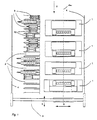
- Figure 1 shows a plan view of a device according to the invention in the form of an automatic line with several processing stations 1 arranged on a center line 1a and several charging stations 2.
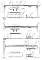
- FIGS. 2 to 10 show side views of the device, seen in the direction of arrow X in FIG. 1.
- the processing stations 1 can be conventional galvanizing baths, degreasing stations or polishing machines, etc.
- a crane 3 which can be seen in FIG. 2, is on rails 4 in over the entire system Movable in the direction of arrow 5.
- the crane 3 carries one which can be moved back and forth in the direction of the arrow 6 Cross offset 7, on which a traverse 7a as a holding device for the Printing cylinder serving clamping system 8 is attached.
- the charging stations 2 are arranged side by side in the number suitable for the system. At the same time, they serve as an input location for introducing the printing cylinders to be processed 9 in the device, as a storage space for storing the printing cylinder 9 before and after editing and as an output place for outputting the printing cylinder 9 from the Contraption. In Figure 1, some charging stations 2 are free, while in other charging stations 2, printing cylinders 9 with partially different sizes are already used.
- the charging stations 2 can also extend the axis of the processing stations 1 be arranged (in Fig. 1 above the processing stations 1).
- the pressure cylinders 9 can be axle cylinders, as shown in the figures are shown. Alternatively, hollow cylinders can also be used. In this case the centering devices and the holding device must be redesigned accordingly his.
- the pressure cylinders 9 are on transport carriages or Cylinder carriage 10 held and can drive back and forth in the factory by the operators become.
- the trolley 10 When introducing the printing cylinder 9 together with its transport carriage 10 into the System, the trolley 10 must be pushed into the charging station 2 until the cylinder axis rests against a stationary stop 11. This applies regardless of the Length of the cylinder 9 and its location on the trolley 10, so that in any case a defined relative position of the printing cylinder 9 is fixed in the charging station 2.
- the Stop 11 can be formed, for example, by a pressure-sensitive sensor, which responds to contact through the cylinder axis.
- the cylinder axis touches the stop 11, it becomes an automatic one, not shown in the figure Braking device activated (for example a magnet) that the carriage 10 in its Holds position until the printing cylinder 9 is back on the trolley after processing 10 is filed.
- Braking device activated (for example a magnet) that the carriage 10 in its Holds position until the printing cylinder 9 is back on the trolley after processing 10 is filed.
- FIG. 2 shows the starting position. Since the components of the device identical to FIG. 1 are identified by the same reference numerals, is a new description of the elements.
- the clamping system 8 has two clamping jaws 8a and 8b, which are relative to the transverse offset 7 can be moved back and forth in the direction of arrow 6.
- clamping system 8 there is a device which can be seen, for example, in FIG 12 for automatically determining the diameter of a printing cylinder by means of a light barrier movable relative to the pressure cylinder 9.
- the transverse offset 7 on the crane 3 moves into a position above the pressure cylinder 9.
- the transverse offset 7 moves in addition to the Jaws 8a, 8b at the same speed with which the jaws 8a, 8b each move.
- the left clamping jaw 8a remains in contact with the bale of the pressure cylinder 9, while the right jaw 8b quickly turns to the other Approximate side of the bale.
- the pressure cylinder 9 is firmly clamped between the two jaws 8a, 8b. ever if necessary, the bale length and the total length of the printing cylinder 9 can be measured become.
- the crane 3 in FIG. 8 then lifts the pressure cylinder 9 and moves it according to the figure 9 to the processing station 1, where, according to FIG. 10, it corresponds to the processing station 1 provided brackets is removed.
- the crane 3 lifts the printing cylinder 9 out of the processing station and leads him back to the trolley 10. There the printing cylinder 9 are stored until the operator finds time, the trolley 10 Pull out together with the pressure cylinder 9 from the charging station 2 and to the next job to transport. After the printing cylinder 9 is placed on the trolley 10 has been released, the car brake, not shown in the figures, is released.
- the crane 3 can also be equipped with a gripper system be equipped by which the cylinder axes are enclosed and raised. Basically, however, the gripper system works exactly like the clamping system 8.
- the entire device is coordinated by a controller, not shown, which can be operated via a master console.
- the operator can use the master console to determine the charging station number, into which he has inserted the pressure cylinder 9 and the cylinder card by means of a barcode reader or the cylinder data (at least the length, the bale length and the circumference) by hand.
- the operator issues the work program , for example by means of the copper thickness, chrome thickness, the polishing program etc. It is also possible to specify the order of processing by giving priority to influence.
- the jaws 8a, 8b can already be separated or are moved together while the crane 3 and the transverse offset 7 are still the approach the next charging station 2.
- the Device 12 has at least one light barrier, which is relative with the aid of crane 3 movable to the pressure cylinder 9 to be detected in its radial or axial direction is. Since the pressure cylinder 9 is not only in the diameter direction from the light barrier 12 can be run over, but also in the longitudinal direction, it is possible in addition to the cylinder diameter also the bale length and - taking into account the distance of the Longitudinal center of the cylinder 9 to the stop 11 - the total length of the printing cylinder 9 to measure or calculate.
- the data determined can already be used in the controller stored data are compared, making a plausibility check possible becomes.
- the control can depend on the determined pressure cylinder dimensions the appropriate work program has already been selected and proposed become.
- the transverse offset 7 moves with the same one Speed to the left when the left holding element touches the cylinder first or to the right if the right holding element 8b makes contact first, whereby then the first touching holding element stands still in relation to the touched bale end. If both holding elements are in contact, the bale length and position are the same of the cylinder known.
Landscapes
- Engineering & Computer Science (AREA)
- Mechanical Engineering (AREA)
- Specific Conveyance Elements (AREA)
- Load-Engaging Elements For Cranes (AREA)
- Carriers, Traveling Bodies, And Overhead Traveling Cranes (AREA)
- Rotary Presses (AREA)
- Electrical Discharge Machining, Electrochemical Machining, And Combined Machining (AREA)
- Feeding Of Workpieces (AREA)
Claims (16)
- Dispositif pour charger au moins un cylindre d'impression (9) dans au moins un poste de traitement (1), comportant plusieurs postes de chargement fixes (2) qui sont conçus chacun comme point d'entrée pour amener le cylindre d'impression (9) dans le dispositif, comme point de stockage pour stocker le cylindre avant et après le traitement, et comme point de sortie pour évacuer le cylindre du dispositif après le traitement ; et comportant un convoyeur (3) pour acheminer le cylindre d'impression entre l'un des postes de chargement et le ou les postes de traitement (1) ; caractérisé en ce que les postes de chargement (2) sont conçus pour recevoir chacun un mécanisme de transport (10) sur lequel le cylindre d'impression (9) est fixé de manière amovible en vue de son transport à l'extérieur du dispositif.
- Dispositif selon la revendication 1, caractérisé en ce que les postes de chargement (2) ont chacun un dispositif de positionnement (11) pour positionner et fixer le mécanisme de transport (10).
- Dispositif selon la revendication 2, caractérisé en ce que le dispositif de positionnement comporte un dispositif de freinage.
- Dispositif selon la revendication 3, caractérisé en ce que le dispositif de freinage est basé sur un principe magnétique.
- Dispositif selon l'une des revendications précédentes, caractérisé en ce que le convoyeur est un appareil de levage (3).
- Dispositif selon la revendication 5, caractérisé en ce que l'appareil de levage (3) présente une traverse (7) qui est mobile dans le sens axial du cylindre d'impression (9) et sur laquelle est prévue une fixation (8) destinée à tenir le cylindre d'impression à ses deux extrémités et mobile par rapport à ladite traverse dans le sens axial du cylindre.
- Dispositif selon la revendication 6, caractérisé en ce que la fixation (8) présente deux éléments de fixation (8a, 8b) mobiles l'un par rapport à l'autre et par rapport à la traverse (7).
- Dispositif selon la revendication 7, caractérisé en ce que les éléments de fixation (8a, 8b), quand la traverse (7) est positionnée au-dessus du cylindre d'impression (9), sont mobiles l'un par rapport à l'autre de telle sorte que lorsque l'un des éléments de fixation (8a) est en position de fixation par rapport au cylindre, la traverse peut être déplacée par rapport au cylindre, dans le sens de cet élément de fixation, à une vitesse définie, et en même temps, l'autre élément de fixation (8b) peut être déplacé dans le sens du premier élément (8a) à la même vitesse que la traverse.
- Dispositif selon l'une des revendications 5 à 8, caractérisé en ce qu'il est prévu sur l'appareil de levage (3) un mécanisme (12) pour définir au moins une dimension du cylindre d'impression (9).
- Dispositif selon l'une des revendications précédentes, caractérisé en ce que par l'intermédiaire d'une commande, on peut entrer à chaque fois une adresse de poste de chargement, des données caractéristiques de cylindre ou un programme de travail pour le cylindre d'impression à traiter (9).
- Procédé pour charger au moins un cylindre d'impression (9) dans au moins un poste de traitement (1), qui consiste à :a) préparer plusieurs postes de chargement fixes (2) qui servent chacun de point d'entrée, de point de stockage et de point de sortie pour le cylindre d'impression (9);b) préparer un convoyeur (3) pour acheminer le cylindre d'impression (9) entre l'un des postes de chargement (2) et le ou les postes de traitement (1) ;c) positionner et fixer dans l'un des postes de chargement (2) un mécanisme de transport (10) portant le cylindre d'impression (9) ;d) acheminer le cylindre d'impression (9) du poste de chargement (2) jusqu'au poste de traitement (1) à l'aide du convoyeur (3) ;e) traiter le cylindre d'impression (9) dans le poste de traitement (1) ;f) ramener le cylindre d'impression (9) du poste de traitement (1) jusqu'au poste de chargement (2) et le déposer sur le mécanisme de transport (10) ; etg) libérer le mécanisme de transport (10).
- Procédé selon la revendication 11, caractérisé en ce que pour traiter plusieurs cylindres d'impression (9), on répète les opérations c) à g), étant précisé que si plusieurs postes de chargement (2) sont impliqués, les opérations c) et g) peuvent être exécutées indépendamment des opérations d) à f).
- Procédé selon la revendication 12, caractérisé en ce que le convoyeur (3), après avoir déposé un cylindre d'impression (9) sur le mécanisme de transport (10), se règle sur le format du prochain cylindre (9) à acheminer.
- Procédé selon la revendication 11, caractérisé par les opérations servant à acheminer le cylindre d'impression :préparer le convoyeur (3) pourvu d'une traverse (7) et d'un dispositif de fixation (8) comprenant deux éléments de fixation (8a, 8b) ;amener la traverse (7) au-dessus du cylindre d'impression (9) porté par le mécanisme de transport (10) ;déplacer le dispositif de fixation (8) de telle sorte que les éléments de fixation (8a, 8b) se trouvent à la hauteur du cylindre d'impression ;déplacer les éléments de fixation (8a, 8b) l'un par rapport à l'autre dans le sens axial du cylindre d'impression (9) jusqu'à ce que l'un des éléments de fixation (8a) touche un côté du cylindre d'impression et ait ainsi atteint la position souhaitée ;déplacer la traverse (7) parallèlement à l'axe du cylindre, dans le sens de l'élément de fixation fixe (8a), à une vitesse définie ;déplacer l'autre élément de fixation (8b) en même temps que la traverse (7), parallèlement à l'axe du cylindre et dans le sens de l'élément de fixation fixe (8a) et à la même vitesse que la traverse (7) ; etarrêter le déplacement de la traverse (7) et de l'élément de fixation (8b) quand celui-ci a atteint l'autre côté du cylindre d'impression (9).
- Procédé selon la revendication 11, caractérisé en ce que, entre les opérations c) et d), on définit au moins une dimension du cylindre d'impression (9) par l'intermédiaire d'un mécanisme (12).
- Procédé selon la revendication 15, caractérisé en ce que le mécanisme (12) pour définir la dimension est déplacé par le convoyeur (3) le long du cylindre d'impression.
Applications Claiming Priority (3)
| Application Number | Priority Date | Filing Date | Title |
|---|---|---|---|
| DE19736698A DE19736698C2 (de) | 1997-08-22 | 1997-08-22 | Vorrichtung zum Beschicken von Bearbeitungsstationen mit Druckzylindern |
| DE19736698 | 1997-08-22 | ||
| PCT/EP1998/003054 WO1999010175A1 (fr) | 1997-08-22 | 1998-05-22 | Dispositif et procede permettant le chargement automatique de cylindres d'impression dans des stations de traitement |
Publications (2)
| Publication Number | Publication Date |
|---|---|
| EP1007361A1 EP1007361A1 (fr) | 2000-06-14 |
| EP1007361B1 true EP1007361B1 (fr) | 2002-03-20 |
Family
ID=7839927
Family Applications (1)
| Application Number | Title | Priority Date | Filing Date |
|---|---|---|---|
| EP98932078A Expired - Lifetime EP1007361B1 (fr) | 1997-08-22 | 1998-05-22 | Dispositif et procede permettant le chargement automatique de cylindres d'impression dans des stations de traitement |
Country Status (6)
| Country | Link |
|---|---|
| US (1) | US6692210B1 (fr) |
| EP (1) | EP1007361B1 (fr) |
| JP (1) | JP3335165B2 (fr) |
| AT (1) | ATE214663T1 (fr) |
| DE (2) | DE19736698C2 (fr) |
| WO (1) | WO1999010175A1 (fr) |
Families Citing this family (15)
| Publication number | Priority date | Publication date | Assignee | Title |
|---|---|---|---|---|
| DE29821652U1 (de) | 1998-12-04 | 1999-02-04 | MAN Roland Druckmaschinen AG, 63075 Offenbach | Wechseleinrichtung für Walzen und Zylinder in einer Druckmaschine |
| DE19921246C2 (de) * | 1999-05-07 | 2003-06-12 | Infineon Technologies Ag | Anlage zur Fertigung von Halbleiterprodukten |
| DE10050750A1 (de) * | 2000-10-13 | 2002-04-25 | Kaspar Walter Gmbh & Co Kg | Kompakte Bearbeitungsanlage für Druckzylinder |
| ITBO20010298A1 (it) * | 2001-05-14 | 2002-11-14 | Gd Spa | Metodo per la realizzazione di pacchetti di sigarette di tipo morbido |
| US6835040B2 (en) * | 2001-11-09 | 2004-12-28 | Neil Quiring | Laser cutting plate conveyor |
| AU2003231430B8 (en) * | 2002-05-13 | 2009-07-30 | Bakvertisi Limited | Apparatus for transporting containers |
| DE10249473A1 (de) * | 2002-10-24 | 2004-05-19 | Emag Maschinenfabrik Gmbh | Werkzeugmaschine |
| DE10338373A1 (de) * | 2003-08-21 | 2005-03-17 | Koenig & Bauer Ag | Vorrichtung zum Wechseln von Druckplatten |
| DE102004021608A1 (de) * | 2004-01-31 | 2005-09-08 | Koenig & Bauer Ag | Druckmaschine mit zumindest einer Druckeinheit zum Bedrucken einer Bedruckstoffbahn im Offsetdruck mit variabler Abschnittslänge |
| EP1593499A1 (fr) * | 2004-05-05 | 2005-11-09 | Swipro AG | Dispositif pour la manutention de cylindres d'impression |
| US7546971B2 (en) * | 2005-04-06 | 2009-06-16 | Catbridge Machinery, L.L.C. | System, apparatus and method for unloading rolled material from a supporting structure |
| ITMI20062163A1 (it) | 2006-11-10 | 2008-05-11 | Gidue S P A | Caricatore per unita' di stampa, particolarmente per macchine da stampa. |
| ITMI20062162A1 (it) | 2006-11-10 | 2008-05-11 | Gidue S P A | Caricatore per teste di stampa e trasformazione, particolarmente per macchine da stampa. |
| DE102011113435A1 (de) | 2011-09-14 | 2013-03-14 | Kaspar Walter Gmbh & Co. Kg | Schubladenlager für Fertigungslinien bei der Druckformherstellung |
| JP6421244B2 (ja) * | 2014-12-04 | 2018-11-07 | ボブスト メックス ソシエテ アノニム | 工具ホルダヘッド、輸送キャリッジ、並びに平坦基材変換用ユニットのための工具を取り付ける及び取り外すための方法 |
Family Cites Families (11)
| Publication number | Priority date | Publication date | Assignee | Title |
|---|---|---|---|---|
| DE2134012A1 (de) * | 1971-04-29 | 1972-11-02 | Cremona, Angelo, Monza (Italien) | Beschickungsvorrichtung für Furniermessermaschinen |
| CH578983A5 (fr) * | 1974-03-19 | 1976-08-31 | Schneebeli H & Co Ag | |
| DE3508195A1 (de) * | 1985-03-08 | 1986-09-11 | Gebr. Dickertmann, Hebezeugfabrik AG, 4800 Bielefeld | Lastaufnahmevorrichtung fuer einen brueckenkran |
| JPH0542913A (ja) * | 1991-07-26 | 1993-02-23 | Ishida Scales Mfg Co Ltd | 包装装置 |
| JPH0639997A (ja) * | 1992-07-17 | 1994-02-15 | Dainippon Printing Co Ltd | 版胴ストッカー |
| DE4224253C1 (de) * | 1992-07-22 | 1994-03-03 | Kaspar Walter Maschf Kg | Verfahren und Einrichtung zum automatischen Bestimmen der Abmessungen von Druckzylindern |
| DK172546B1 (da) * | 1993-02-03 | 1998-12-21 | Kammann Maschf Werner | Trykkeværk med udskiftelige dele samt anordning og fremgangsmåde til udskiftning af dele i et sådant trykkeværk |
| IT1265131B1 (it) * | 1993-06-25 | 1996-10-31 | Cerutti Spa Off Mec | Procedimento e mezzi per il cambio automatico del cilindro di stampa in una macchina da stampa rotativa |
| JPH07165064A (ja) * | 1993-12-16 | 1995-06-27 | Mitsui Eng & Shipbuild Co Ltd | 搬送設備 |
| DE4413807C1 (de) * | 1994-04-20 | 1995-09-14 | Windmoeller & Hoelscher | Vorrichtung zum Wechseln der Zylinder an einer Druckmaschine |
| DE4442265A1 (de) * | 1994-11-28 | 1996-05-30 | Roland Man Druckmasch | Transportsystem zum Transport von Druckformen |
-
1997
- 1997-08-22 DE DE19736698A patent/DE19736698C2/de not_active Expired - Lifetime
-
1998
- 1998-05-22 WO PCT/EP1998/003054 patent/WO1999010175A1/fr not_active Ceased
- 1998-05-22 EP EP98932078A patent/EP1007361B1/fr not_active Expired - Lifetime
- 1998-05-22 DE DE59803452T patent/DE59803452D1/de not_active Expired - Lifetime
- 1998-05-22 US US09/485,977 patent/US6692210B1/en not_active Expired - Lifetime
- 1998-05-22 AT AT98932078T patent/ATE214663T1/de not_active IP Right Cessation
- 1998-05-22 JP JP2000507532A patent/JP3335165B2/ja not_active Expired - Lifetime
Also Published As
| Publication number | Publication date |
|---|---|
| US6692210B1 (en) | 2004-02-17 |
| EP1007361A1 (fr) | 2000-06-14 |
| JP2001514097A (ja) | 2001-09-11 |
| DE59803452D1 (de) | 2002-04-25 |
| DE19736698C2 (de) | 2001-09-13 |
| ATE214663T1 (de) | 2002-04-15 |
| WO1999010175A1 (fr) | 1999-03-04 |
| DE19736698A1 (de) | 1999-02-25 |
| JP3335165B2 (ja) | 2002-10-15 |
Similar Documents
| Publication | Publication Date | Title |
|---|---|---|
| DE19736698C2 (de) | Vorrichtung zum Beschicken von Bearbeitungsstationen mit Druckzylindern | |
| DE3222657C2 (de) | Vorrichtung zum automatischen Montieren von Teilen auf Chassis | |
| DE4003445C2 (fr) | ||
| EP3268165B1 (fr) | Système de moyens de serrage automatisable | |
| DE3219460C2 (de) | Unbemannte Beförderungsanlage zum Transportieren von Werkstücken zwischen Lagerregalen und Werkzeugmaschinen | |
| EP3528999B1 (fr) | Procédé de chargement pour une machine-outil et dispositif de transfert d'outil | |
| EP1990151B1 (fr) | Machine d'usinage | |
| DE3614165A1 (de) | Transportsystem fuer serienfertigungen | |
| DE202017106030U1 (de) | Honmaschine und Verwendung einer Honmaschine | |
| DE2753801A1 (de) | Verfahren und vorrichtung zum auswechseln von werkzeugkoepfen an werkzeugmaschinen | |
| EP1860593B1 (fr) | Machine stationnaire pour l'application de matière de bordure sur des éléments en forme de plaque | |
| EP1712330B1 (fr) | Unité de fabrication | |
| EP0427005B1 (fr) | Procédé et dispositif pour échanger des pots à rubans de fibres dans les machines textiles | |
| EP1097025A1 (fr) | Dispositif d'usinage automatise de pieces | |
| EP1459838A1 (fr) | Centre d'usinage vertical | |
| DE2312902C3 (de) | Einrichtung zur Wärmebehandlung von Werkstücken | |
| EP0150662B1 (fr) | Dispositif pour charger et décharger des machines pour le travail des circuits imprimés, notamment des machines pour le montage de composants | |
| DE3936947A1 (de) | Anordnung zur beschickung von vorzugsweise einspindeligen nc-leiterplatten-koordinatenbohrmaschinen mit zu bohrenden leiterplatten bzw. zum abtransport fertig gebohrter leiterplatten | |
| EP3124153B1 (fr) | Dispositif d'usinage de pièces à usiner, notamment des lames de scie | |
| EP0467101A1 (fr) | Dispositif pour garnir les broches d'un cantre | |
| DE102018102417A1 (de) | Vorrichtung zum Transportieren und Ausrichten von einem oder mehreren flächigen Bauteilen | |
| DE19747995A1 (de) | Selbstladendes Bearbeitungszentrum mit Werkstück- und Werkzeugmagazinen | |
| EP0451477A2 (fr) | Dispositif de remplacement automatique de bobines de mèche vides avec bobines de mèche pleines dans un râtelier à bobines d'un métier à filer à anneaux | |
| DE4308676A1 (de) | Vorrichtung zum automatischen Zuführen, Eingeben und Abführen von Werkstücken bei Werkzeugmaschinen | |
| DE4109877C2 (fr) |
Legal Events
| Date | Code | Title | Description |
|---|---|---|---|
| PUAI | Public reference made under article 153(3) epc to a published international application that has entered the european phase |
Free format text: ORIGINAL CODE: 0009012 |
|
| 17P | Request for examination filed |
Effective date: 20000113 |
|
| AK | Designated contracting states |
Kind code of ref document: A1 Designated state(s): AT CH DE ES FR GB IT LI NL |
|
| GRAG | Despatch of communication of intention to grant |
Free format text: ORIGINAL CODE: EPIDOS AGRA |
|
| 17Q | First examination report despatched |
Effective date: 20010530 |
|
| GRAG | Despatch of communication of intention to grant |
Free format text: ORIGINAL CODE: EPIDOS AGRA |
|
| GRAH | Despatch of communication of intention to grant a patent |
Free format text: ORIGINAL CODE: EPIDOS IGRA |
|
| GRAH | Despatch of communication of intention to grant a patent |
Free format text: ORIGINAL CODE: EPIDOS IGRA |
|
| REG | Reference to a national code |
Ref country code: GB Ref legal event code: IF02 |
|
| GRAA | (expected) grant |
Free format text: ORIGINAL CODE: 0009210 |
|
| AK | Designated contracting states |
Kind code of ref document: B1 Designated state(s): AT CH DE ES FR GB IT LI NL |
|
| PG25 | Lapsed in a contracting state [announced via postgrant information from national office to epo] |
Ref country code: NL Free format text: LAPSE BECAUSE OF FAILURE TO SUBMIT A TRANSLATION OF THE DESCRIPTION OR TO PAY THE FEE WITHIN THE PRESCRIBED TIME-LIMIT Effective date: 20020320 Ref country code: GB Free format text: LAPSE BECAUSE OF FAILURE TO SUBMIT A TRANSLATION OF THE DESCRIPTION OR TO PAY THE FEE WITHIN THE PRESCRIBED TIME-LIMIT Effective date: 20020320 Ref country code: FR Free format text: LAPSE BECAUSE OF FAILURE TO SUBMIT A TRANSLATION OF THE DESCRIPTION OR TO PAY THE FEE WITHIN THE PRESCRIBED TIME-LIMIT Effective date: 20020320 |
|
| REF | Corresponds to: |
Ref document number: 214663 Country of ref document: AT Date of ref document: 20020415 Kind code of ref document: T |
|
| REG | Reference to a national code |
Ref country code: CH Ref legal event code: NV Representative=s name: BRAUN & PARTNER PATENT-, MARKEN-, RECHTSANWAELTE Ref country code: CH Ref legal event code: EP |
|
| REF | Corresponds to: |
Ref document number: 59803452 Country of ref document: DE Date of ref document: 20020425 |
|
| PG25 | Lapsed in a contracting state [announced via postgrant information from national office to epo] |
Ref country code: AT Free format text: LAPSE BECAUSE OF NON-PAYMENT OF DUE FEES Effective date: 20020522 |
|
| NLV1 | Nl: lapsed or annulled due to failure to fulfill the requirements of art. 29p and 29m of the patents act | ||
| GBV | Gb: ep patent (uk) treated as always having been void in accordance with gb section 77(7)/1977 [no translation filed] |
Effective date: 20020320 |
|
| PG25 | Lapsed in a contracting state [announced via postgrant information from national office to epo] |
Ref country code: ES Free format text: LAPSE BECAUSE OF FAILURE TO SUBMIT A TRANSLATION OF THE DESCRIPTION OR TO PAY THE FEE WITHIN THE PRESCRIBED TIME-LIMIT Effective date: 20020925 |
|
| EN | Fr: translation not filed | ||
| PLBE | No opposition filed within time limit |
Free format text: ORIGINAL CODE: 0009261 |
|
| STAA | Information on the status of an ep patent application or granted ep patent |
Free format text: STATUS: NO OPPOSITION FILED WITHIN TIME LIMIT |
|
| 26N | No opposition filed |
Effective date: 20021223 |
|
| REG | Reference to a national code |
Ref country code: CH Ref legal event code: NV Representative=s name: BRAUNPAT BRAUN EDER AG |
|
| PGFP | Annual fee paid to national office [announced via postgrant information from national office to epo] |
Ref country code: CH Payment date: 20120522 Year of fee payment: 15 |
|
| REG | Reference to a national code |
Ref country code: CH Ref legal event code: PL |
|
| PG25 | Lapsed in a contracting state [announced via postgrant information from national office to epo] |
Ref country code: LI Free format text: LAPSE BECAUSE OF NON-PAYMENT OF DUE FEES Effective date: 20130531 Ref country code: CH Free format text: LAPSE BECAUSE OF NON-PAYMENT OF DUE FEES Effective date: 20130531 |
|
| PGFP | Annual fee paid to national office [announced via postgrant information from national office to epo] |
Ref country code: DE Payment date: 20170523 Year of fee payment: 20 |
|
| PGFP | Annual fee paid to national office [announced via postgrant information from national office to epo] |
Ref country code: IT Payment date: 20170524 Year of fee payment: 20 |
|
| REG | Reference to a national code |
Ref country code: DE Ref legal event code: R071 Ref document number: 59803452 Country of ref document: DE |