EP1006397B1 - Objektiv für eine Kamera - Google Patents
Objektiv für eine Kamera Download PDFInfo
- Publication number
- EP1006397B1 EP1006397B1 EP99124103A EP99124103A EP1006397B1 EP 1006397 B1 EP1006397 B1 EP 1006397B1 EP 99124103 A EP99124103 A EP 99124103A EP 99124103 A EP99124103 A EP 99124103A EP 1006397 B1 EP1006397 B1 EP 1006397B1
- Authority
- EP
- European Patent Office
- Prior art keywords
- camera
- interchangeable lens
- lens
- contacts
- optical signal
- Prior art date
- Legal status (The legal status is an assumption and is not a legal conclusion. Google has not performed a legal analysis and makes no representation as to the accuracy of the status listed.)
- Expired - Lifetime
Links
- 230000003287 optical effect Effects 0.000 claims description 12
- 230000008054 signal transmission Effects 0.000 description 4
- 230000005540 biological transmission Effects 0.000 description 3
- 230000005611 electricity Effects 0.000 description 3
- 230000001960 triggered effect Effects 0.000 description 2
- 230000036039 immunity Effects 0.000 description 1
- 230000007257 malfunction Effects 0.000 description 1
Images

Classifications
-
- G—PHYSICS
- G03—PHOTOGRAPHY; CINEMATOGRAPHY; ANALOGOUS TECHNIQUES USING WAVES OTHER THAN OPTICAL WAVES; ELECTROGRAPHY; HOLOGRAPHY
- G03B—APPARATUS OR ARRANGEMENTS FOR TAKING PHOTOGRAPHS OR FOR PROJECTING OR VIEWING THEM; APPARATUS OR ARRANGEMENTS EMPLOYING ANALOGOUS TECHNIQUES USING WAVES OTHER THAN OPTICAL WAVES; ACCESSORIES THEREFOR
- G03B17/00—Details of cameras or camera bodies; Accessories therefor
- G03B17/02—Bodies
- G03B17/12—Bodies with means for supporting objectives, supplementary lenses, filters, masks, or turrets
- G03B17/14—Bodies with means for supporting objectives, supplementary lenses, filters, masks, or turrets interchangeably
Definitions
- the invention relates to a camera, in particular a system camera, with a camera body and an interchangeable lens that with a Connection device, in particular a bayonet attachment, in one Connection device of the camera housing, in particular one Bayonet mount, is interchangeable.
- Such a lens can usually be used as a bayonet trained connection device on a camera housing Camera are put on and over the camera body with electricity be supplied.
- Such lenses are particularly for system cameras with interchangeable lenses (interchangeable lenses), such as e.g. SLR cameras and viewfinder system cameras, interesting, where the lenses for the transport of the SLR camera can be removed from the camera body and in particular also the optional use of different lenses each after the required image adjustment.
- the lenses generally have electrical consumers, such as an electrically operated focus adjustment device and an electrically operated aperture adjustment device.
- the lens and the camera housing have several electrical contacts on, some of which power the lens and others for transmitting signals between the lens and the camera body for the selection of the different lens settings serve.
- the electrical contacts are in the ring-shaped area of the bayonet lock around the optical Path of the cylindrical lens arranged around.
- Such camera lenses are e.g. known from US 4,637,704A or US 4,440,484A.
- the invention has for its object the aforementioned To further develop the camera in a relatively simple way Connection between lens and camera body at the same time high functional and interference immunity can be guaranteed.
- this object is achieved by a camera, in particular system camera, with a camera housing and a Interchangeable lens that with a connection device, in particular a bayonet attachment, in a connection device of the camera housing, especially a bayonet mount, interchangeable is hingable, being for the power supply of electrical actuators in the interchangeable lens
- the connection device of the Camera housing has only two power contacts, which two connection contacts in the connection device of the interchangeable lens are assigned, characterized in that for the transmission of Control signals from the interchangeable lens to the camera housing and / or conversely, only an optocoupling in the interface is provided, each having an optical signal generator and has associated with this signal pickup.
- the signal transmission from the power supply separated by an optocoupling for signal transmission is used. This prevents unwanted contact between the signal connections and power supply connections of the lens and the camera body when retracting the lens occur more. Between the electrical contacts of the Power supply and optical means can basically neither electricity nor information is transmitted.
- optical signal transmission can advantageously the optical signal output and the optical signal recording separately by connecting one connector each for signal delivery only and another is only used for signal recording becomes. This can be done in particular by using LEDs for signal transmission and photodiodes for signal recording can be achieved.
- a bayonet attachment 1 can be screw holes 10 on the body an interchangeable lens 13 are attached.
- the bayonet attachment 1 has protrusions projecting radially outwards in a known manner 11 and can be in a bayonet mount 1 'of a camera housing 14 of a system camera, e.g. an SLR camera or a search system camera.
- a connection area 12 of the bayonet attachment 1 are electrical connection contacts 2, 3 arranged. Next to them are an infrared light emitting diode (IR LED) 4 and an infrared photodiode 5 in the connection area 12 provided.
- the connection contacts 2, 3 and Light-emitting diode 4 and photodiode serving as optical connection means 5 are annular from one another within the connection surface 12 spaced.
- the light emitting diode 4 via the pins 6, 7 and the photodiode 5 is connected to the lens body via the pins 8, 9 become.
- the electrical connection contacts 2, 3 are with the lens body also via electrical, not shown Contacts connected.
- an IR light emitting diode 15 On a corresponding contact surface 12 'in the bayonet holder 1 'of the camera housing 14 are an IR light emitting diode 15, an IR photodiode 16 and two power supply contacts 2 ', 3' such arranged that when installing the lens bayonet 1 in the camera housing 14 the housing-side light-emitting diode 15 of the photodiode 5, the housing-side photodiode 16 of the light emitting diode 4 and the power supply contacts 2 ', 3' opposite the connection contacts 2, 3.
- a power supply for electrical Actuators in the interchangeable lens such as one electrically operated focus adjustment device 17 and / or a electrically operable aperture adjustment device 18 via the Connection contacts 2, 3 can be guaranteed.
- the one from the interchangeable lens 13 electrical signals to be transmitted are via the Pins 6, 7 of the light-emitting diode 4 supplied in optical or IR signals converted by the photodiode 16 of the camera body 14 recorded and converted into electrical signals; correspondingly by the light emitting diode (LED) 15 of the camera housing 14 emitted (IR) light signals from the photodiode 5 recorded, converted into electrical signals and via the Pins 8, 9 forwarded to the actuators 17, 18.
- LED light emitting diode
- IR IR
- the interchangeable lens 13 with bayonet attachment 1 is known Way to the bayonet receptacle 1 'of the camera housing 14, by first putting it on axially and then twisting it becomes.
Landscapes
- Physics & Mathematics (AREA)
- General Physics & Mathematics (AREA)
- Structure And Mechanism Of Cameras (AREA)
- Exposure Control For Cameras (AREA)
- Lens Barrels (AREA)
Description
- Figur 1
- eine als Bajonettaufsatz ausgebildete Anschlusseinrichtung eines Wechselobjektivs,
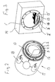
- Figur 2
- in gegenüber Figur 1 kleinerem Maßstab ein Wechselobjektiv mit einem Bajonettaufsatz gemäß Figur 1 und
- Figur 3
- in schematischer Darstellung ein Kameragehäuse mit einer Bajonettaufnahme.
Claims (5)
- Kamera, insbesondere Systemkamera, mit einem Kameragehäuse (14) und einem Wechselobjektiv (13), das mit einer Anschlusseinrichtung (1), inbesondere einem Bajonettaufsatz, in einer Verbindungseinrichtung (1') des Kameragehäuses (14), insbesondere einer Bajonettaufnahme, auswechselbar anrenkbar ist, wobei für die Stromversorgung elektrischer Stelleinrichtungen (17, 18) im Wechselobjektiv (13) die Verbindungseinrichtung (1') des Kameragehäuses (14) nur zwei Stromversorgungskontakte (2', 3') aufweist, denen in der Anschlusseinrichtung (1) des Wechselobjektives (13) zwei Anschlusskontakte (2, 3) zugeordnet sind, dadurch gekennzeichnet, daß zur Übertragung von Steuersignalen vom Wechselobjektiv (13) auf das Kamergehäuse (14) und/oder umgekehrt in der Schnittstelle (1, 1') ausschließlich eine Optokopplung vorgesehen ist, die jeweils einen optischen Signalgeber (4, 15) und einen diesem zugeordneten Signalaufnehmer (5, 16) aufweist.
- Kamera nach Anspruch 1, dadurch gekennzeichnet, dass der optische Signalgeber zumindest eine Leuchtdiode (4, 15) und der optische Signalaufnehmer zumindest eine Fotodiode (5, 16) aufweisen.
- Kamera nach Anspruch 1 oder 2, dadurch gekennzeichnet, dass der in der Anschlusseinrichtung (1) des Wechselobjektives (13) angeordnete optische Signalgeber (4) und/oder Signalaufnehmer (5) über elektrische Kontakte (6, 7, 8, 9), vorzugsweise Stiftkontakte, mit dem Objektivkörper elektrisch verbunden sind.
- Kamera nach Anspruch 1, 2 oder 3, dadurch gekennzeichnet, dass das Wechselobjektiv (13) eine elektrisch betätigbare Fokusverstelleinrichtung (17) aufweist.
- Kamera nach einem der vorhergehenden Ansprüche, dadurch gekennzeichnet, dass das Wechselobjektiv (13) eine elektrisch betätigbare Blendenverstelleinrichtung (18) aufweist.
Applications Claiming Priority (2)
| Application Number | Priority Date | Filing Date | Title |
|---|---|---|---|
| DE19855977A DE19855977C2 (de) | 1998-12-04 | 1998-12-04 | Objektiv für eine Kamera |
| DE19855977 | 1998-12-04 |
Publications (2)
| Publication Number | Publication Date |
|---|---|
| EP1006397A1 EP1006397A1 (de) | 2000-06-07 |
| EP1006397B1 true EP1006397B1 (de) | 2004-03-03 |
Family
ID=7889969
Family Applications (1)
| Application Number | Title | Priority Date | Filing Date |
|---|---|---|---|
| EP99124103A Expired - Lifetime EP1006397B1 (de) | 1998-12-04 | 1999-12-02 | Objektiv für eine Kamera |
Country Status (5)
| Country | Link |
|---|---|
| US (1) | US6269222B1 (de) |
| EP (1) | EP1006397B1 (de) |
| JP (1) | JP2000171848A (de) |
| DE (2) | DE19855977C2 (de) |
| TW (1) | TW535018B (de) |
Cited By (2)
| Publication number | Priority date | Publication date | Assignee | Title |
|---|---|---|---|---|
| DE102006019449A1 (de) * | 2006-04-24 | 2007-10-25 | Leica Camera Ag | Verfahren und Vorrichtung zur Identifizierung von Wechselobjektiven |
| US7625144B2 (en) | 2006-01-17 | 2009-12-01 | Leica Camera Ag | Interchangeable lens with optically readable marking |
Families Citing this family (15)
| Publication number | Priority date | Publication date | Assignee | Title |
|---|---|---|---|---|
| US7567290B2 (en) * | 2004-03-29 | 2009-07-28 | Fujifilm Corporation | Camera system, camera body, imaging lens unit, and interchangeable lens camera |
| US20100068718A1 (en) * | 2008-08-22 | 2010-03-18 | Hooper Dennis G | Methods and Compositions for Identifying Yeast |
| US9131134B2 (en) * | 2013-05-24 | 2015-09-08 | Sony Corporation | Camera and optical apparatus |
| US9429818B2 (en) | 2014-04-04 | 2016-08-30 | Here Global B.V. | Accessory identification and configuration and corresponding accessory |
| EP3250106A4 (de) | 2015-01-26 | 2019-01-02 | Visunex Medical Systems Co. Ltd. | Wegwerfbare kappe für eine augenabbildungsvorrichtung und zugehörige verfahren |
| DE102017106588A1 (de) * | 2017-03-28 | 2018-10-04 | Carl Zeiss Microscopy Gmbh | Übertragung von Daten in einem optischen System |
| TWI709808B (zh) | 2017-05-31 | 2020-11-11 | 日商佳能股份有限公司 | 安裝件設備和配件 |
| RU2714842C2 (ru) | 2017-05-31 | 2020-02-19 | Кэнон Кабусики Кайся | Устройство захвата изображения и аксессуары |
| RU2714847C2 (ru) | 2017-05-31 | 2020-02-19 | Кэнон Кабусики Кайся | Устройство захвата изображения и аксессуары |
| JP6615264B2 (ja) | 2017-05-31 | 2019-12-04 | キヤノン株式会社 | 撮像装置、レンズ装置、アクセサリ、カメラシステム |
| CN113126393A (zh) * | 2017-05-31 | 2021-07-16 | 佳能株式会社 | 镜头设备、摄像设备和中间配件 |
| US10666842B2 (en) | 2017-05-31 | 2020-05-26 | Canon Kabushiki Kaisha | Imaging apparatus, lens apparatus, and intermediate accessory |
| EP3796084B1 (de) | 2017-05-31 | 2023-10-25 | Canon Kabushiki Kaisha | Zubehör und abbildungsvorrichtung |
| DE102017113411B4 (de) * | 2017-06-19 | 2019-08-01 | Carl Zeiss Industrielle Messtechnik Gmbh | Beleuchtungssystem für ein Koordinatenmessgerät, Koordinatenmessgerät und Verfahren |
| USD1036535S1 (en) * | 2022-12-12 | 2024-07-23 | Fei Lei | Camera lens mount adapter |
Family Cites Families (7)
| Publication number | Priority date | Publication date | Assignee | Title |
|---|---|---|---|---|
| JPS6235071Y2 (de) * | 1981-04-21 | 1987-09-07 | ||
| JPS58105130A (ja) * | 1981-12-17 | 1983-06-22 | Asahi Optical Co Ltd | 光フアイバによるレンズ側情報伝達機構 |
| DE3227404A1 (de) * | 1982-07-22 | 1984-01-26 | Ernst Leitz Wetzlar Gmbh, 6330 Wetzlar | Verfahren und einrichtungen zum uebertragen von informationen |
| DE3438322A1 (de) * | 1984-10-19 | 1986-04-24 | Ernst Leitz Wetzlar Gmbh, 6330 Wetzlar | Verfahren und einrichtung zur uebertragung von signaldaten |
| DE3443443A1 (de) * | 1984-10-19 | 1986-05-28 | Ernst Leitz Wetzlar Gmbh, 6330 Wetzlar | Einrichtungen zur uebertragung von signaldaten |
| JPS6189821U (de) * | 1984-11-19 | 1986-06-11 | ||
| US5079578A (en) * | 1988-10-13 | 1992-01-07 | Canon Kabushiki Kaisha | Camera system |
-
1998
- 1998-12-04 DE DE19855977A patent/DE19855977C2/de not_active Expired - Fee Related
-
1999
- 1999-11-10 TW TW088119651A patent/TW535018B/zh not_active IP Right Cessation
- 1999-11-30 JP JP11340560A patent/JP2000171848A/ja active Pending
- 1999-12-02 EP EP99124103A patent/EP1006397B1/de not_active Expired - Lifetime
- 1999-12-02 DE DE59908718T patent/DE59908718D1/de not_active Expired - Fee Related
- 1999-12-03 US US09/453,443 patent/US6269222B1/en not_active Expired - Fee Related
Cited By (4)
| Publication number | Priority date | Publication date | Assignee | Title |
|---|---|---|---|---|
| US7625144B2 (en) | 2006-01-17 | 2009-12-01 | Leica Camera Ag | Interchangeable lens with optically readable marking |
| DE102006019449A1 (de) * | 2006-04-24 | 2007-10-25 | Leica Camera Ag | Verfahren und Vorrichtung zur Identifizierung von Wechselobjektiven |
| EP1852741A1 (de) * | 2006-04-24 | 2007-11-07 | Leica Camera AG | Verfahren und Vorrichtung zur Identifizierung von Wechselobjektiven |
| US7848634B2 (en) | 2006-04-24 | 2010-12-07 | Leica Camera Ag | Method and apparatus for identifying interchangeable lenses |
Also Published As
| Publication number | Publication date |
|---|---|
| DE59908718D1 (de) | 2004-04-08 |
| TW535018B (en) | 2003-06-01 |
| US6269222B1 (en) | 2001-07-31 |
| DE19855977A1 (de) | 2000-06-21 |
| DE19855977C2 (de) | 2002-06-27 |
| JP2000171848A (ja) | 2000-06-23 |
| EP1006397A1 (de) | 2000-06-07 |
Similar Documents
| Publication | Publication Date | Title |
|---|---|---|
| EP1006397B1 (de) | Objektiv für eine Kamera | |
| DE3744342C2 (de) | ||
| DE69022708T2 (de) | Gehäuse für ein Paar von optischen Vorrichtungen. | |
| DE102014101642B4 (de) | Schnallenanordnung mit Leuchtdiode und optischer Führung und Fahrzeug mit einer derartigen Schnallenanordnung | |
| DE69215215T2 (de) | Integrierte Halbleiterschaltungsscheibe eines elektrischen Verbinders | |
| DE10154834A1 (de) | Stecker und Steckeraufnahme für ein optoelektronisches Steckersystem | |
| EP0463214A1 (de) | Sende- und Empfangsmodul für eine bidirektionale optische Nachrichten- und Signalübertragung | |
| DE68910352T2 (de) | Wechselobjektif-Mechanismus. | |
| EP3035665B1 (de) | Kamerasystem mit modularer leiterplattenanordnung | |
| DE68922472T2 (de) | Optisches Gerät. | |
| DE112007000658T5 (de) | Kameramodul und Verfahren zu dessen Montage | |
| EP2951059B1 (de) | Anschlussmodul mit lichtanzeiger | |
| DE102012203170B4 (de) | Eine festverbindungs(FC)-artige optoelektronische Anordnung und ein Verfahren zur Verwendung einer solchen Anordnung | |
| EP1846793B1 (de) | Led-modul zur beleuchtung in einem mikroskop | |
| EP1543365A1 (de) | Anschlussvorrichtung zum lösbaren verbinden wenigstens eines lichtwellenleiters mit wenigstens einem optoelektronischen bauelement sowie verfahren zum montieren einer solchen anschlussvorrichtung | |
| WO2019238445A1 (de) | Fertigungsvorrichtung und verfahren | |
| EP1456602B1 (de) | Sensor zur visuellen positionserfassung ( bauelement, substrat ) mit einer modularen beleuchtungseinheit | |
| EP0120457A2 (de) | Optische Sender- und Empfängervorrichtung | |
| DE102004048960B4 (de) | Aktiver optischer Verbinder | |
| DE3126349C2 (de) | Zwischen Objektiv und Kamerakörper einfügbarer Konverter für photographische Kameras | |
| DE102006005308B4 (de) | System zum Steuern eines ladungsgekoppelten Bauelementes | |
| WO2015135676A1 (de) | Bildaufnahmevorrichtung, insbesondere zur fahrzeugvermessung | |
| DE102018129122A1 (de) | Ladesteckverbinder mit einem Streuelement zum Abstrahlen und/oder Empfangen von Licht | |
| DE3510453A1 (de) | Kontaktanordnung | |
| DE112012000922B4 (de) | Optisches Modul und Verfahren zur Herstellung eines optischen Moduls |
Legal Events
| Date | Code | Title | Description |
|---|---|---|---|
| PUAI | Public reference made under article 153(3) epc to a published international application that has entered the european phase |
Free format text: ORIGINAL CODE: 0009012 |
|
| AK | Designated contracting states |
Kind code of ref document: A1 Designated state(s): DE FR GB |
|
| AX | Request for extension of the european patent |
Free format text: AL;LT;LV;MK;RO;SI |
|
| 17P | Request for examination filed |
Effective date: 20000420 |
|
| AKX | Designation fees paid |
Free format text: DE FR GB |
|
| GRAH | Despatch of communication of intention to grant a patent |
Free format text: ORIGINAL CODE: EPIDOS IGRA |
|
| GRAS | Grant fee paid |
Free format text: ORIGINAL CODE: EPIDOSNIGR3 |
|
| GRAA | (expected) grant |
Free format text: ORIGINAL CODE: 0009210 |
|
| AK | Designated contracting states |
Kind code of ref document: B1 Designated state(s): DE FR GB |
|
| REG | Reference to a national code |
Ref country code: GB Ref legal event code: FG4D Free format text: NOT ENGLISH |
|
| REF | Corresponds to: |
Ref document number: 59908718 Country of ref document: DE Date of ref document: 20040408 Kind code of ref document: P |
|
| GBT | Gb: translation of ep patent filed (gb section 77(6)(a)/1977) |
Effective date: 20040322 |
|
| PG25 | Lapsed in a contracting state [announced via postgrant information from national office to epo] |
Ref country code: GB Free format text: LAPSE BECAUSE OF NON-PAYMENT OF DUE FEES Effective date: 20041202 |
|
| ET | Fr: translation filed | ||
| PLBE | No opposition filed within time limit |
Free format text: ORIGINAL CODE: 0009261 |
|
| STAA | Information on the status of an ep patent application or granted ep patent |
Free format text: STATUS: NO OPPOSITION FILED WITHIN TIME LIMIT |
|
| 26N | No opposition filed |
Effective date: 20041206 |
|
| PG25 | Lapsed in a contracting state [announced via postgrant information from national office to epo] |
Ref country code: DE Free format text: LAPSE BECAUSE OF NON-PAYMENT OF DUE FEES Effective date: 20050701 |
|
| GBPC | Gb: european patent ceased through non-payment of renewal fee |
Effective date: 20041202 |
|
| PG25 | Lapsed in a contracting state [announced via postgrant information from national office to epo] |
Ref country code: FR Free format text: LAPSE BECAUSE OF NON-PAYMENT OF DUE FEES Effective date: 20050831 |
|
| REG | Reference to a national code |
Ref country code: FR Ref legal event code: ST |