EP1006397B1 - Camera lens - Google Patents
Camera lens Download PDFInfo
- Publication number
- EP1006397B1 EP1006397B1 EP99124103A EP99124103A EP1006397B1 EP 1006397 B1 EP1006397 B1 EP 1006397B1 EP 99124103 A EP99124103 A EP 99124103A EP 99124103 A EP99124103 A EP 99124103A EP 1006397 B1 EP1006397 B1 EP 1006397B1
- Authority
- EP
- European Patent Office
- Prior art keywords
- camera
- interchangeable lens
- lens
- contacts
- optical signal
- Prior art date
- Legal status (The legal status is an assumption and is not a legal conclusion. Google has not performed a legal analysis and makes no representation as to the accuracy of the status listed.)
- Expired - Lifetime
Links
- 230000003287 optical effect Effects 0.000 claims description 12
- 230000008054 signal transmission Effects 0.000 description 4
- 230000005540 biological transmission Effects 0.000 description 3
- 230000005611 electricity Effects 0.000 description 3
- 230000001960 triggered effect Effects 0.000 description 2
- 230000036039 immunity Effects 0.000 description 1
- 230000007257 malfunction Effects 0.000 description 1
Images

Classifications
-
- G—PHYSICS
- G03—PHOTOGRAPHY; CINEMATOGRAPHY; ANALOGOUS TECHNIQUES USING WAVES OTHER THAN OPTICAL WAVES; ELECTROGRAPHY; HOLOGRAPHY
- G03B—APPARATUS OR ARRANGEMENTS FOR TAKING PHOTOGRAPHS OR FOR PROJECTING OR VIEWING THEM; APPARATUS OR ARRANGEMENTS EMPLOYING ANALOGOUS TECHNIQUES USING WAVES OTHER THAN OPTICAL WAVES; ACCESSORIES THEREFOR
- G03B17/00—Details of cameras or camera bodies; Accessories therefor
- G03B17/02—Bodies
- G03B17/12—Bodies with means for supporting objectives, supplementary lenses, filters, masks, or turrets
- G03B17/14—Bodies with means for supporting objectives, supplementary lenses, filters, masks, or turrets interchangeably
Definitions
- the invention relates to a camera, in particular a system camera, with a camera body and an interchangeable lens that with a Connection device, in particular a bayonet attachment, in one Connection device of the camera housing, in particular one Bayonet mount, is interchangeable.
- Such a lens can usually be used as a bayonet trained connection device on a camera housing Camera are put on and over the camera body with electricity be supplied.
- Such lenses are particularly for system cameras with interchangeable lenses (interchangeable lenses), such as e.g. SLR cameras and viewfinder system cameras, interesting, where the lenses for the transport of the SLR camera can be removed from the camera body and in particular also the optional use of different lenses each after the required image adjustment.
- the lenses generally have electrical consumers, such as an electrically operated focus adjustment device and an electrically operated aperture adjustment device.
- the lens and the camera housing have several electrical contacts on, some of which power the lens and others for transmitting signals between the lens and the camera body for the selection of the different lens settings serve.
- the electrical contacts are in the ring-shaped area of the bayonet lock around the optical Path of the cylindrical lens arranged around.
- Such camera lenses are e.g. known from US 4,637,704A or US 4,440,484A.
- the invention has for its object the aforementioned To further develop the camera in a relatively simple way Connection between lens and camera body at the same time high functional and interference immunity can be guaranteed.
- this object is achieved by a camera, in particular system camera, with a camera housing and a Interchangeable lens that with a connection device, in particular a bayonet attachment, in a connection device of the camera housing, especially a bayonet mount, interchangeable is hingable, being for the power supply of electrical actuators in the interchangeable lens
- the connection device of the Camera housing has only two power contacts, which two connection contacts in the connection device of the interchangeable lens are assigned, characterized in that for the transmission of Control signals from the interchangeable lens to the camera housing and / or conversely, only an optocoupling in the interface is provided, each having an optical signal generator and has associated with this signal pickup.
- the signal transmission from the power supply separated by an optocoupling for signal transmission is used. This prevents unwanted contact between the signal connections and power supply connections of the lens and the camera body when retracting the lens occur more. Between the electrical contacts of the Power supply and optical means can basically neither electricity nor information is transmitted.
- optical signal transmission can advantageously the optical signal output and the optical signal recording separately by connecting one connector each for signal delivery only and another is only used for signal recording becomes. This can be done in particular by using LEDs for signal transmission and photodiodes for signal recording can be achieved.
- a bayonet attachment 1 can be screw holes 10 on the body an interchangeable lens 13 are attached.
- the bayonet attachment 1 has protrusions projecting radially outwards in a known manner 11 and can be in a bayonet mount 1 'of a camera housing 14 of a system camera, e.g. an SLR camera or a search system camera.
- a connection area 12 of the bayonet attachment 1 are electrical connection contacts 2, 3 arranged. Next to them are an infrared light emitting diode (IR LED) 4 and an infrared photodiode 5 in the connection area 12 provided.
- the connection contacts 2, 3 and Light-emitting diode 4 and photodiode serving as optical connection means 5 are annular from one another within the connection surface 12 spaced.
- the light emitting diode 4 via the pins 6, 7 and the photodiode 5 is connected to the lens body via the pins 8, 9 become.
- the electrical connection contacts 2, 3 are with the lens body also via electrical, not shown Contacts connected.
- an IR light emitting diode 15 On a corresponding contact surface 12 'in the bayonet holder 1 'of the camera housing 14 are an IR light emitting diode 15, an IR photodiode 16 and two power supply contacts 2 ', 3' such arranged that when installing the lens bayonet 1 in the camera housing 14 the housing-side light-emitting diode 15 of the photodiode 5, the housing-side photodiode 16 of the light emitting diode 4 and the power supply contacts 2 ', 3' opposite the connection contacts 2, 3.
- a power supply for electrical Actuators in the interchangeable lens such as one electrically operated focus adjustment device 17 and / or a electrically operable aperture adjustment device 18 via the Connection contacts 2, 3 can be guaranteed.
- the one from the interchangeable lens 13 electrical signals to be transmitted are via the Pins 6, 7 of the light-emitting diode 4 supplied in optical or IR signals converted by the photodiode 16 of the camera body 14 recorded and converted into electrical signals; correspondingly by the light emitting diode (LED) 15 of the camera housing 14 emitted (IR) light signals from the photodiode 5 recorded, converted into electrical signals and via the Pins 8, 9 forwarded to the actuators 17, 18.
- LED light emitting diode
- IR IR
- the interchangeable lens 13 with bayonet attachment 1 is known Way to the bayonet receptacle 1 'of the camera housing 14, by first putting it on axially and then twisting it becomes.
Landscapes
- Physics & Mathematics (AREA)
- General Physics & Mathematics (AREA)
- Structure And Mechanism Of Cameras (AREA)
- Exposure Control For Cameras (AREA)
- Lens Barrels (AREA)
Description
Die Erfindung betrifft eine Kamera, insbesondere Systemkamera, mit einem Kameragehäuse und einem Wechselobjektiv, das mit einer Anschlusseinrichtung, inbesondere einem Bajonettaufsatz, in einer Verbindungseinrichtung des Kameragehäuses, insbesondere einer Bajonettaufnahme, auswechselbar anrenkbar ist.The invention relates to a camera, in particular a system camera, with a camera body and an interchangeable lens that with a Connection device, in particular a bayonet attachment, in one Connection device of the camera housing, in particular one Bayonet mount, is interchangeable.
Ein derartiges Objektiv kann über die üblicherweise als Bajonett ausgebildete Anschlusseinrichtung auf ein Kameraghäuse einer Kamera aufgesetzt werden und über das Kameragehäuse mit Strom versorgt werden. Solche Objektive sind insbesondere für Systemkameras mit austauschbaren Objektiven (Wechselobjektiven), wie z.B. Spiegelreflexsystemkameras und Suchersystemkameras, interessant, bei denen die Objektive für den Transport der Spiegelreflexkamera vom Kameragehäuse entfernt werden können und insbesondere auch den wahlweisen Einsatz verschiedener Objektive je nach der erforderlichen Bildeinstellung ermöglichen. Die Objektive weisen im Allgemeinen elektrische Verbraucher, wie zum Beispiel eine elektrisch betätigbare Fokusverstelleinrichtung und eine elektrisch betätigbare Blendenverstelleinrichtung auf. Das Objektiv und das Kameragehäuse weisen mehrere elektrische Kontakte auf, von denen einige zur Stromversorgung des Objektivs und andere zur Übertragung von Signalen zwischen dem Objektiv und dem Kameragehäuse für die Auswahl der verschiedenen Objektiveinstellungen dienen. Die elektrischen Kontakte sind dabei in dem ringförmigen Bereich des Bajonettverschlusses um den optischen Pfad des zylinderförmigen Objektivs herum angeordnet.Such a lens can usually be used as a bayonet trained connection device on a camera housing Camera are put on and over the camera body with electricity be supplied. Such lenses are particularly for system cameras with interchangeable lenses (interchangeable lenses), such as e.g. SLR cameras and viewfinder system cameras, interesting, where the lenses for the transport of the SLR camera can be removed from the camera body and in particular also the optional use of different lenses each after the required image adjustment. The lenses generally have electrical consumers, such as an electrically operated focus adjustment device and an electrically operated aperture adjustment device. The The lens and the camera housing have several electrical contacts on, some of which power the lens and others for transmitting signals between the lens and the camera body for the selection of the different lens settings serve. The electrical contacts are in the ring-shaped area of the bayonet lock around the optical Path of the cylindrical lens arranged around.
Derartige Kameraobjektive sind z.B. aus der US 4 637 704A oder der US 4 440 484A bekannt.Such camera lenses are e.g. known from US 4,637,704A or US 4,440,484A.
Da die elektrischen Kontakte an dem Objektiv und dem Kameragehäuse im Wesentlichen ringförmig nebeneinander angeordnet sind, kann es bei dem Anrenken eines Objektivs an das Kameragehäuse zu unerwünschten kurzzeitigen elektrischen Verbindungen zwischen Kontakten kommen, die nicht miteinander verbunden werden sollen. Durch diese kurzzeitigen elektrischen Verbindungen können Kurzschlüsse und Fehlverbindungen ausgelöst werden, die unter Umständen zu einer Beschädigung von elektronischen Teilen des Objektivs oder Kameragehäuses führen können oder Funktionsstörungen in den Verstelleinrichtungen des Objektivs bewirken. Weiterhin können durch in den Verbindungsbereich eintretenden Schmutz oder Feuchtigkeit die Kontakte abgenutzt und blockiert werden.Because the electrical contacts on the lens and the camera body are arranged essentially in a ring next to one another, it can happen when a lens is attached to the camera housing undesirable short-term electrical connections between Contacts come that should not be connected. These short-term electrical connections can cause short circuits and incorrect connections are triggered, which may damage to electronic parts of the lens or camera body or malfunction cause in the adjustment of the lens. Farther can be caused by dirt entering the connection area or moisture the contacts are worn and blocked.
Aus der US 4 541 700A ist es bekannt, nur 1 oder zwei Kontaktpunkte zur Stromversorgung sowie zur Datenübertragung zu benutzen.From US 4,541,700A it is known to use only 1 or two contact points for power supply and data transmission.
Der Erfindung liegt die Aufgabe zugrunde, die eingangs genannte Kamera dahingehend weiterzubilden, dass eine relativ einfache Verbindung zwischen Objektiv und Kameragehäuse bei gleichzeitig hoher Funktions- und Störsicherheit gewährleistet werden kann.The invention has for its object the aforementioned To further develop the camera in a relatively simple way Connection between lens and camera body at the same time high functional and interference immunity can be guaranteed.
Diese Aufgabe wird erfindungsgemäß gelöst durch eine Kamera, insbesondere Systemkamera, mit einem Kameragehäuse und einem Wechselobjektiv, das mit einer Anschlusseinrichtung, inbesondere einem Bajonettaufsatz, in einer Verbindungseinrichtung des Kameragehäuses, insbesondere einer Bajonettaufnahme, auswechselbar anrenkbar ist, wobei für die Stromversorgung elektrischer Stelleinrichtungen im Wechselobjektiv die Verbindungseinrichtung des Kameragehäuses nur zwei Stromversorgungskontakte aufweist, denen in der Anschlusseinrichtung des Wechselobjektives zwei Anschlusskontakte zugeordnet sind, dadurch gekennzeichnet, daß zür Übertragung von Steuersignalen vom Wechselobjektiv auf das Kamergehäuse und/oder umgekehrt in der Schnittstelle ausschließlich eine Optokopplung vorgesehen ist, die jeweils einen optischen Signalgeber und einen diesem zugeordneten Signalaufnehmer aufweist.According to the invention, this object is achieved by a camera, in particular system camera, with a camera housing and a Interchangeable lens that with a connection device, in particular a bayonet attachment, in a connection device of the camera housing, especially a bayonet mount, interchangeable is hingable, being for the power supply of electrical actuators in the interchangeable lens, the connection device of the Camera housing has only two power contacts, which two connection contacts in the connection device of the interchangeable lens are assigned, characterized in that for the transmission of Control signals from the interchangeable lens to the camera housing and / or conversely, only an optocoupling in the interface is provided, each having an optical signal generator and has associated with this signal pickup.
Erfindungsgemäß wird somit die Signalübertragung von der Stromversorgung getrennt, indem eine Optokopplung zur Signalübertragung verwendet wird. Hierdurch kann kein unerwünschter Kontakt zwischen den Signalanschlüssen und Stromversorgungsanschlüssen des Objektivs und des Kameragehäuses beim Einrenken des Objektivs mehr auftreten. Zwischen den elektrischen Kontakten der Stromversorgung und den optischen Mitteln kann grundsätzlich weder Strom noch eine Information übertragen werden.According to the invention, the signal transmission from the power supply separated by an optocoupling for signal transmission is used. This prevents unwanted contact between the signal connections and power supply connections of the lens and the camera body when retracting the lens occur more. Between the electrical contacts of the Power supply and optical means can basically neither electricity nor information is transmitted.
Zwar kann grundsätzlich zwischen den zwei Anschlusskontakten des Objektivs und den zwei Stromversorgungskontakten des Kameragehäuses ein kurzzeitiger Fehlanschluss auftreten, bei denen ein Kontakt des Objektivs den falschen Kontakt des Kameragehäuses berührt und die anderen Kontakte freiliegen. Da in einem derartigen Fall jedoch kein Stromkreis geschlossen wird, kann hierbei auch kein Strom fließen. Somit kann bei einer erfindungsgemäßen Ausbildung des Objektivs bzw. einer Kamera mit einem derartigen Objektiv kein Kurzschluss mehr ausgelöst und keine Fehlinformation mehr übertragen werden.Basically, between the two connection contacts of the Lens and the two power contacts on the camera body a short-term incorrect connection occur in which a Contact of the lens the wrong contact of the camera body touched and the other contacts are exposed. Because in such a However, if no circuit is closed, this can no electricity flow either. Thus, in an inventive Training the lens or a camera with such a Lens no longer triggered short circuit and no misinformation be transmitted more.
Bei der optischen Signalübertragung können vorteilhafterweise die optische Signalabgabe und die optische Signalaufnahme getrennt werden, indem jeweils ein Anschluss lediglich für die Signalabgabe und ein anderer lediglich für die Signalaufnahme genutzt wird. Dies kann insbesondere durch die Verwendung von Leuchtdioden zur Signalaussendung und Fotodioden zur Signalaufnahme erreicht werden. When optical signal transmission can advantageously the optical signal output and the optical signal recording separately by connecting one connector each for signal delivery only and another is only used for signal recording becomes. This can be done in particular by using LEDs for signal transmission and photodiodes for signal recording can be achieved.
In der Zeichnung ist eine als Beispiel dienende Ausführungform der Erfindung dargestellt. Es zeigen
- Figur 1
- eine als Bajonettaufsatz ausgebildete Anschlusseinrichtung eines Wechselobjektivs,
-
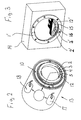
Figur 2 - in gegenüber Figur 1 kleinerem Maßstab ein Wechselobjektiv mit einem Bajonettaufsatz gemäß Figur 1 und
-
Figur 3 - in schematischer Darstellung ein Kameragehäuse mit einer Bajonettaufnahme.
- Figure 1
- a connection device of an interchangeable lens designed as a bayonet attachment,
- Figure 2
- on a smaller scale compared to FIG. 1, an interchangeable lens with a bayonet attachment according to FIGS. 1 and
- Figure 3
- a schematic representation of a camera housing with a bayonet mount.
Ein Bajonettaufsatz 1 kann über Schraubenlöcher 10 an dem Körper
eines Wechselobjektivs 13 befestigt werden. Der Bajonettaufsatz
1 weist in bekannter Weise radial nach außen ragende Vorsprünge
11 auf und kann in einer Bajonettaufnahme 1' eines Kameragehäuses
14 einer Systemkamera, wie z.B. einer Spiegelreflexkamera
oder einer Suchsystemkamera, angerenkt werden. An einer Anschlussfläche
12 des Bajonettaufsatzes 1 sind elektrische Anschlusskontakte
2, 3 angeordnet. Neben ihnen sind eine Infrarot-Leuchtdiode
(IR-LED) 4 und eine Infrarot-Fotodiode 5 in der Anschlussfläche
12 vorgesehen. Die Anschlusskontakte 2, 3 und die
als optische Anschlussmittel dienende Leuchtdiode 4 und Fotodiode
5 sind innerhalb der Anschlussfläche 12 ringförmig voneinander
beabstandet. Bei Befestigung des Bajonettaufsatzes 1 an dem
Objektivkörper können die Leuchtdiode 4 über die Stifte 6, 7 und
die Fotodiode 5 über die Stifte 8, 9 an den Objektivkörper angeschlossen
werden. Die elektrischen Anschlusskontakte 2, 3 werden
mit dem Objektivkörper ebenfalls über nicht gezeigte elektrische
Kontakte verbunden.A bayonet attachment 1 can be
An einer entsprechenden Anlagefläche 12' in der Bajonettaufnahme
1' des Kameragehäuses 14 sind eine IR-Leuchtdiode 15, eine IR-Fotodiode
16 und zwei Stromversorgungskontakte 2', 3' derartig
angeordnet, dass bei Einbau des Objektivbajonetts 1 in das Kameragehäuse
14 die gehäuseseitige Leuchtdiode 15 der Fotodiode 5,
die gehäuseseitige Fotodiode 16 der Leuchtdiode 4 und die Stromversorgungskontakte
2', 3' den Anschlusskontakten 2, 3 gegenüberliegen.
Somit kann eine Stromversorgung für elektrische
Stelleinrichtungen im Wechselobjektiv, wie zum Beispiel eine
elektrisch betätigbare Fokusverstelleinrichtung 17 und/oder eine
elektrisch betätigbare Blendenverstelleinrichtung 18 über die
Anschlusskontakte 2, 3 gewährleistet werden. Die vom Wechselobjektiv
13 auszusendenden elektrischen Signale werden über die
Stifte 6, 7 der Leuchtdiode 4 zugeführt, in optische bzw. IR-Signale
umgewandelt, die von der Fotodiode 16 des Kameragehäuses
14 aufgenommen und in elektrische Signale umgewandelt werden;
entsprechend werden von der Leuchtdiode (LED) 15 des Kameragehäuses
14 ausgesendete (IR-)Lichtsignale von der Fotodiode 5
aufgenommen, in elektrische Signale umgewandelt und über die
Stifte 8, 9 zu den Stelleinrichtungen 17, 18 weitergeleitet. Da
die Signalaufnahme des Wechselobjektivs 13 über die Fotodiode 5
und die Signalabgabe über die Leuchtdiode 4 voneinander getrennt
sind, ist eine schnelle Datenübertragung gewährleistet.On a corresponding contact surface 12 'in the bayonet holder
1 'of the
Das Wechselobjektiv 13 mit Bajonettaufsatz 1 wird in bekannter
Weise an die Bajonettaufnahme 1' des Kameragehäuses 14 angerenkt,
indem es zunächst axial aufgesetzt und anschließend verdreht
wird.The
Claims (5)
- Camera, in particular system camera, with a camera housing (14) and an interchangeable lens (13), which can be interchangeably fitted by means of a connection device (1), in particular a bayonet attachment, in a connecting device (1') of the camera housing (14), in particular a bayonet receptacle, in which, for supplying power to electrical actuating devices (17, 18) in the interchangeable lens (13), the connecting device (1') of the camera housing (14) has only two power supply contacts (2', 3'), to which two connection contacts (2, 3) are assigned in the connection device (1) of the interchangeable lens (13), characterized in that exclusively one optocoupling is provided in the interface (1, 1') for the purpose of transmitting control signals from the interchangeable lens (13) to the camera housing (14) and/or vice versa, said optocoupling in each case having an optical signal transmitter (4, 15) and a signal pickup (5, 16) assigned thereto.
- Camera according to claim 1, characterized in that the optical signal transmitter has at least one light emitting diode (4, 15) and the optical signal pickup has at least one photodiode (5, 16).
- Camera according to claim 1 or 2, characterized in that the optical signal transmitter (4) and/or signal pickup (5) arranged in the connection device (1) of the interchangeable lens (13) are electrically connected to the lens body via electrical contacts (6, 7, 8, 9), preferably pin contacts.
- Camera according to claim 1, 2, or 3, characterized in that the interchangeable lens (13) has an electrically actuable focus adjusting device (17).
- Camera according to one of the preceding claims, characterized in that the interchangeable lens (13) has an electrically actuable aperture adjusting device (18).
Applications Claiming Priority (2)
| Application Number | Priority Date | Filing Date | Title |
|---|---|---|---|
| DE19855977A DE19855977C2 (en) | 1998-12-04 | 1998-12-04 | Lens for a camera |
| DE19855977 | 1998-12-04 |
Publications (2)
| Publication Number | Publication Date |
|---|---|
| EP1006397A1 EP1006397A1 (en) | 2000-06-07 |
| EP1006397B1 true EP1006397B1 (en) | 2004-03-03 |
Family
ID=7889969
Family Applications (1)
| Application Number | Title | Priority Date | Filing Date |
|---|---|---|---|
| EP99124103A Expired - Lifetime EP1006397B1 (en) | 1998-12-04 | 1999-12-02 | Camera lens |
Country Status (5)
| Country | Link |
|---|---|
| US (1) | US6269222B1 (en) |
| EP (1) | EP1006397B1 (en) |
| JP (1) | JP2000171848A (en) |
| DE (2) | DE19855977C2 (en) |
| TW (1) | TW535018B (en) |
Cited By (2)
| Publication number | Priority date | Publication date | Assignee | Title |
|---|---|---|---|---|
| DE102006019449A1 (en) * | 2006-04-24 | 2007-10-25 | Leica Camera Ag | Interchangeable lens identification method, involves arranging defined optical radiation of two or more, preferably six light emitters, and forming binary coded signal for identification of lens |
| US7625144B2 (en) | 2006-01-17 | 2009-12-01 | Leica Camera Ag | Interchangeable lens with optically readable marking |
Families Citing this family (15)
| Publication number | Priority date | Publication date | Assignee | Title |
|---|---|---|---|---|
| US7567290B2 (en) * | 2004-03-29 | 2009-07-28 | Fujifilm Corporation | Camera system, camera body, imaging lens unit, and interchangeable lens camera |
| US20100068718A1 (en) * | 2008-08-22 | 2010-03-18 | Hooper Dennis G | Methods and Compositions for Identifying Yeast |
| US9131134B2 (en) * | 2013-05-24 | 2015-09-08 | Sony Corporation | Camera and optical apparatus |
| US9429818B2 (en) | 2014-04-04 | 2016-08-30 | Here Global B.V. | Accessory identification and configuration and corresponding accessory |
| US9848773B2 (en) | 2015-01-26 | 2017-12-26 | Visunex Medical Systems Co. Ltd. | Disposable cap for an eye imaging apparatus and related methods |
| DE102017106588A1 (en) * | 2017-03-28 | 2018-10-04 | Carl Zeiss Microscopy Gmbh | Transmission of data in an optical system |
| TWI709808B (en) | 2017-05-31 | 2020-11-11 | 日商佳能股份有限公司 | Mount apparatus and accessories |
| RU2714847C2 (en) | 2017-05-31 | 2020-02-19 | Кэнон Кабусики Кайся | Image capturing device and accessories |
| JP6552681B2 (en) | 2017-05-31 | 2019-07-31 | キヤノン株式会社 | Accessories, imaging device |
| CN208479765U (en) | 2017-05-31 | 2019-02-05 | 佳能株式会社 | Picture pick-up device, lens apparatus and intermediate accessory |
| JP6548780B2 (en) | 2017-05-31 | 2019-07-24 | キヤノン株式会社 | Lens device, imaging device, intermediate accessory device |
| RU2714842C2 (en) | 2017-05-31 | 2020-02-19 | Кэнон Кабусики Кайся | Image capturing device and accessories |
| EP3410193B1 (en) | 2017-05-31 | 2020-03-04 | Canon Kabushiki Kaisha | Imaging apparatus, lens apparatus, and intermediate accessory |
| DE102017113411B4 (en) * | 2017-06-19 | 2019-08-01 | Carl Zeiss Industrielle Messtechnik Gmbh | Illumination system for a coordinate measuring machine, coordinate measuring machine and method |
| USD1036535S1 (en) * | 2022-12-12 | 2024-07-23 | Fei Lei | Camera lens mount adapter |
Family Cites Families (7)
| Publication number | Priority date | Publication date | Assignee | Title |
|---|---|---|---|---|
| JPS6235071Y2 (en) * | 1981-04-21 | 1987-09-07 | ||
| JPS58105130A (en) * | 1981-12-17 | 1983-06-22 | Asahi Optical Co Ltd | Lens side information transmission mechanism using optical fiber |
| DE3227404A1 (en) * | 1982-07-22 | 1984-01-26 | Ernst Leitz Wetzlar Gmbh, 6330 Wetzlar | METHOD AND DEVICES FOR TRANSMITTING INFORMATION |
| DE3438322A1 (en) * | 1984-10-19 | 1986-04-24 | Ernst Leitz Wetzlar Gmbh, 6330 Wetzlar | Method and device for transmitting signal data |
| DE3443443A1 (en) * | 1984-10-19 | 1986-05-28 | Ernst Leitz Wetzlar Gmbh, 6330 Wetzlar | Device for transmitting signal data |
| JPS6189821U (en) * | 1984-11-19 | 1986-06-11 | ||
| US5079578A (en) * | 1988-10-13 | 1992-01-07 | Canon Kabushiki Kaisha | Camera system |
-
1998
- 1998-12-04 DE DE19855977A patent/DE19855977C2/en not_active Expired - Fee Related
-
1999
- 1999-11-10 TW TW088119651A patent/TW535018B/en not_active IP Right Cessation
- 1999-11-30 JP JP11340560A patent/JP2000171848A/en active Pending
- 1999-12-02 EP EP99124103A patent/EP1006397B1/en not_active Expired - Lifetime
- 1999-12-02 DE DE59908718T patent/DE59908718D1/en not_active Expired - Fee Related
- 1999-12-03 US US09/453,443 patent/US6269222B1/en not_active Expired - Fee Related
Cited By (4)
| Publication number | Priority date | Publication date | Assignee | Title |
|---|---|---|---|---|
| US7625144B2 (en) | 2006-01-17 | 2009-12-01 | Leica Camera Ag | Interchangeable lens with optically readable marking |
| DE102006019449A1 (en) * | 2006-04-24 | 2007-10-25 | Leica Camera Ag | Interchangeable lens identification method, involves arranging defined optical radiation of two or more, preferably six light emitters, and forming binary coded signal for identification of lens |
| EP1852741A1 (en) * | 2006-04-24 | 2007-11-07 | Leica Camera AG | Method and device for identifying interchangeable lenses |
| US7848634B2 (en) | 2006-04-24 | 2010-12-07 | Leica Camera Ag | Method and apparatus for identifying interchangeable lenses |
Also Published As
| Publication number | Publication date |
|---|---|
| DE19855977A1 (en) | 2000-06-21 |
| JP2000171848A (en) | 2000-06-23 |
| EP1006397A1 (en) | 2000-06-07 |
| DE59908718D1 (en) | 2004-04-08 |
| US6269222B1 (en) | 2001-07-31 |
| DE19855977C2 (en) | 2002-06-27 |
| TW535018B (en) | 2003-06-01 |
Similar Documents
| Publication | Publication Date | Title |
|---|---|---|
| EP1006397B1 (en) | Camera lens | |
| DE3744342C2 (en) | ||
| DE69022708T2 (en) | Housing for a pair of optical devices. | |
| DE68923049T2 (en) | Camera system. | |
| EP0463214B1 (en) | Transmitting- and receiving module for a bidirectional optical communication- and signal-transmission | |
| EP1353412B1 (en) | Modular connector | |
| DE69215215T2 (en) | Integrated semiconductor circuit board of an electrical connector | |
| DE10154834A1 (en) | Plug and plug receptacle for an opto-electronic plug system | |
| DE69511079T2 (en) | SELF-TESTING A WIRELESS CONNECTION IN A NUMERICALLY CONTROLLED MACHINE | |
| DE102007002145A1 (en) | endoscope | |
| DE19943120A1 (en) | Connection system for an electronic endoscope has switch element in first or second power supply lines that is switched from off to the on state when two connector halves are fully engaged | |
| DE102018102905A1 (en) | Sensor attachment structure and sensor adapter | |
| EP3035665B1 (en) | Camera system having a modular printed circuit board arrangement | |
| DE112007000658T5 (en) | Camera module and method for its assembly | |
| EP2951059B1 (en) | Connection module with light indicators | |
| DE102012203170B4 (en) | A fixed connection (FC) type optoelectronic device and a method of using such device | |
| EP1846793B1 (en) | Led-module used for illumination in a microscope | |
| DE102018212116A1 (en) | Lens body, lens and lens system | |
| EP1543365A1 (en) | Connector device for the detachable connection of at least one light wave guide to at least one optoelectronic component and method for assembly of such a connector device | |
| EP1456602B1 (en) | Sensor for the visual position detection (component, substrate) comprising a modular lighting device | |
| EP0120457A2 (en) | Optical transmitter and receiver | |
| DE102004048960B4 (en) | Active optical connector | |
| DE3126349C2 (en) | Converter for photographic cameras that can be inserted between the lens and the camera body | |
| DE102006005308B4 (en) | System for controlling a charge-coupled device | |
| DE102018129122A1 (en) | Charging connector with a diffusing element for emitting and / or receiving light |
Legal Events
| Date | Code | Title | Description |
|---|---|---|---|
| PUAI | Public reference made under article 153(3) epc to a published international application that has entered the european phase |
Free format text: ORIGINAL CODE: 0009012 |
|
| AK | Designated contracting states |
Kind code of ref document: A1 Designated state(s): DE FR GB |
|
| AX | Request for extension of the european patent |
Free format text: AL;LT;LV;MK;RO;SI |
|
| 17P | Request for examination filed |
Effective date: 20000420 |
|
| AKX | Designation fees paid |
Free format text: DE FR GB |
|
| GRAH | Despatch of communication of intention to grant a patent |
Free format text: ORIGINAL CODE: EPIDOS IGRA |
|
| GRAS | Grant fee paid |
Free format text: ORIGINAL CODE: EPIDOSNIGR3 |
|
| GRAA | (expected) grant |
Free format text: ORIGINAL CODE: 0009210 |
|
| AK | Designated contracting states |
Kind code of ref document: B1 Designated state(s): DE FR GB |
|
| REG | Reference to a national code |
Ref country code: GB Ref legal event code: FG4D Free format text: NOT ENGLISH |
|
| REF | Corresponds to: |
Ref document number: 59908718 Country of ref document: DE Date of ref document: 20040408 Kind code of ref document: P |
|
| GBT | Gb: translation of ep patent filed (gb section 77(6)(a)/1977) |
Effective date: 20040322 |
|
| PG25 | Lapsed in a contracting state [announced via postgrant information from national office to epo] |
Ref country code: GB Free format text: LAPSE BECAUSE OF NON-PAYMENT OF DUE FEES Effective date: 20041202 |
|
| ET | Fr: translation filed | ||
| PLBE | No opposition filed within time limit |
Free format text: ORIGINAL CODE: 0009261 |
|
| STAA | Information on the status of an ep patent application or granted ep patent |
Free format text: STATUS: NO OPPOSITION FILED WITHIN TIME LIMIT |
|
| 26N | No opposition filed |
Effective date: 20041206 |
|
| PG25 | Lapsed in a contracting state [announced via postgrant information from national office to epo] |
Ref country code: DE Free format text: LAPSE BECAUSE OF NON-PAYMENT OF DUE FEES Effective date: 20050701 |
|
| GBPC | Gb: european patent ceased through non-payment of renewal fee |
Effective date: 20041202 |
|
| PG25 | Lapsed in a contracting state [announced via postgrant information from national office to epo] |
Ref country code: FR Free format text: LAPSE BECAUSE OF NON-PAYMENT OF DUE FEES Effective date: 20050831 |
|
| REG | Reference to a national code |
Ref country code: FR Ref legal event code: ST |