JP6548780B2 - Lens device, imaging device, intermediate accessory device - Google Patents
Lens device, imaging device, intermediate accessory device Download PDFInfo
- Publication number
- JP6548780B2 JP6548780B2 JP2018103884A JP2018103884A JP6548780B2 JP 6548780 B2 JP6548780 B2 JP 6548780B2 JP 2018103884 A JP2018103884 A JP 2018103884A JP 2018103884 A JP2018103884 A JP 2018103884A JP 6548780 B2 JP6548780 B2 JP 6548780B2
- Authority
- JP
- Japan
- Prior art keywords
- voltage
- lens
- terminal
- electrical contact
- communication
- Prior art date
- Legal status (The legal status is an assumption and is not a legal conclusion. Google has not performed a legal analysis and makes no representation as to the accuracy of the status listed.)
- Active
Links
Images


Classifications
-
- H—ELECTRICITY
- H04—ELECTRIC COMMUNICATION TECHNIQUE
- H04N—PICTORIAL COMMUNICATION, e.g. TELEVISION
- H04N23/00—Cameras or camera modules comprising electronic image sensors; Control thereof
- H04N23/60—Control of cameras or camera modules
- H04N23/66—Remote control of cameras or camera parts, e.g. by remote control devices
- H04N23/663—Remote control of cameras or camera parts, e.g. by remote control devices for controlling interchangeable camera parts based on electronic image sensor signals
-
- G—PHYSICS
- G03—PHOTOGRAPHY; CINEMATOGRAPHY; ANALOGOUS TECHNIQUES USING WAVES OTHER THAN OPTICAL WAVES; ELECTROGRAPHY; HOLOGRAPHY
- G03B—APPARATUS OR ARRANGEMENTS FOR TAKING PHOTOGRAPHS OR FOR PROJECTING OR VIEWING THEM; APPARATUS OR ARRANGEMENTS EMPLOYING ANALOGOUS TECHNIQUES USING WAVES OTHER THAN OPTICAL WAVES; ACCESSORIES THEREFOR
- G03B17/00—Details of cameras or camera bodies; Accessories therefor
- G03B17/02—Bodies
- G03B17/12—Bodies with means for supporting objectives, supplementary lenses, filters, masks, or turrets
- G03B17/14—Bodies with means for supporting objectives, supplementary lenses, filters, masks, or turrets interchangeably
-
- G—PHYSICS
- G03—PHOTOGRAPHY; CINEMATOGRAPHY; ANALOGOUS TECHNIQUES USING WAVES OTHER THAN OPTICAL WAVES; ELECTROGRAPHY; HOLOGRAPHY
- G03B—APPARATUS OR ARRANGEMENTS FOR TAKING PHOTOGRAPHS OR FOR PROJECTING OR VIEWING THEM; APPARATUS OR ARRANGEMENTS EMPLOYING ANALOGOUS TECHNIQUES USING WAVES OTHER THAN OPTICAL WAVES; ACCESSORIES THEREFOR
- G03B17/00—Details of cameras or camera bodies; Accessories therefor
- G03B17/56—Accessories
- G03B17/565—Optical accessories, e.g. converters for close-up photography, tele-convertors, wide-angle convertors
-
- G—PHYSICS
- G03—PHOTOGRAPHY; CINEMATOGRAPHY; ANALOGOUS TECHNIQUES USING WAVES OTHER THAN OPTICAL WAVES; ELECTROGRAPHY; HOLOGRAPHY
- G03B—APPARATUS OR ARRANGEMENTS FOR TAKING PHOTOGRAPHS OR FOR PROJECTING OR VIEWING THEM; APPARATUS OR ARRANGEMENTS EMPLOYING ANALOGOUS TECHNIQUES USING WAVES OTHER THAN OPTICAL WAVES; ACCESSORIES THEREFOR
- G03B7/00—Control of exposure by setting shutters, diaphragms or filters, separately or conjointly
- G03B7/20—Control of exposure by setting shutters, diaphragms or filters, separately or conjointly in accordance with change of lens
-
- H—ELECTRICITY
- H04—ELECTRIC COMMUNICATION TECHNIQUE
- H04N—PICTORIAL COMMUNICATION, e.g. TELEVISION
- H04N23/00—Cameras or camera modules comprising electronic image sensors; Control thereof
- H04N23/50—Constructional details
- H04N23/55—Optical parts specially adapted for electronic image sensors; Mounting thereof
Description
本発明は、相互に通信が可能なレンズ装置、撮像装置、中間アクセサリ装置に関する。 The present invention relates to a lens device, an imaging device, and an intermediate accessory device that can communicate with each other.
撮像装置に対して着脱可能な交換レンズなどのアクセサリ装置は、撮像装置から電源の供給を受けたり、撮像装置と通信を行ったりすることで動作する。このため、撮像装置のマウント部とアクセサリ装置のマウント部には共に複数の電気接点が設けられている。撮像装置にアクセサリ装置が装着されると撮像装置側の電気接点とアクセサリ装置側の電気接点が接触し、撮像装置とアクセサリ装置が電気的に接続される。 An accessory device such as an interchangeable lens that is attachable to and detachable from an imaging device operates by receiving power supply from the imaging device and communicating with the imaging device. For this reason, a plurality of electrical contacts are provided on both the mount portion of the imaging device and the mount portion of the accessory device. When the accessory device is attached to the imaging device, the electrical contact on the imaging device side contacts the electrical contact on the accessory device side, and the imaging device and the accessory device are electrically connected.
撮像装置に動作電圧の異なる複数種類のアクセサリ装置が装着され得る場合、撮像装置は装着されたアクセサリ装置の種類を適切に判別する必要がある。 When multiple types of accessory devices having different operating voltages can be attached to the imaging device, the imaging device needs to appropriately determine the type of the attached accessory device.
特許文献1には、装着されたアクセサリ装置の種類を判別するための電気接点を有する撮像装置が記載されている。特許文献1の撮像装置は、この電気接点の電圧値を読み取ることで装着されたアクセサリ装置の種類を判別できる。
アクセサリ装置の判別のための電気接点が他の電気接点とショートすると、撮像装置が装着されたアクセサリ装置の種類を誤判別してしまう場合がある。アクセサリ装置の種類が誤判別されると、アクセサリ装置に定格外の電圧が印加されてしまうおそれがある。しかしながら、特許文献1にはアクセサリ装置の判別のための電気接点が他の電気接点とショートした場合について考慮されていない。
If the electrical contact for discriminating the accessory device is shorted with another electrical contact, the type of the accessory device to which the imaging device is attached may be erroneously discriminated. If the type of the accessory device is misjudged, there is a possibility that an unrated voltage may be applied to the accessory device. However,
本発明の目的は、アクセサリ装置の装着状況を適切に判別できる撮像装置を提供することである。 An object of the present invention is to provide an imaging device capable of appropriately determining the mounting state of an accessory device.
本発明の撮像装置は、第1の電圧により通信を行う第1のレンズ装置と、前記第1の電圧とは異なる第2の電圧により通信を行う第2のレンズ装置が着脱可能に装着される撮像装置であって、装着されたレンズ装置の種類を判別する判別手段と、複数の電気接点が配列されたマウント部と、を有し、前記複数の電気接点は、装着されたレンズ装置に前記第1の電圧および前記第2の電圧の少なくとも一方と異なる第3の電圧の電力を供給するための第1の電気接点と、前記第1の電気接点のグラウンドレベルとなる第2の電気接点と、前記判別手段による前記撮像装置に装着されたレンズ装置の種類の判別に用いられる第3の電気接点と、を含み、前記第1の電気接点と前記第2の電気接点は、前記複数の電気接点の配列において、共に前記第3の電気接点の隣に配置されており、前記第3の電気接点の電圧が前記第3の電圧および前記第2の電気接点の電圧を共に含まない第1の電圧範囲の電圧である場合、前記判別手段は前記撮像装置に装着されたレンズ装置を前記第1のレンズ装置であると判別し、前記第3の電気接点の電圧が、前記第1の電圧範囲と前記第3の電圧と前記第2の電気接点の電圧を含まない第2の電圧範囲の電圧である場合、前記判別手段は前記撮像装置に装着されたレンズ装置を前記第2のレンズ装置であると判別することを特徴とする。 In the imaging apparatus according to the present invention, a first lens device performing communication with a first voltage and a second lens device performing communication with a second voltage different from the first voltage are detachably mounted. It is an imaging device, and it has a judgment part which judges a kind of lens device with which it was equipped, and a mount part in which a plurality of electrical contacts are arranged, and the plurality of electrical contacts are attached to the lens device attached. A first electrical contact for supplying power of a third voltage different from at least one of a first voltage and the second voltage, and a second electrical contact serving as a ground level of the first electrical contact A third electric contact used to determine the type of lens apparatus mounted on the image pickup apparatus by the judging means, the first electric contact and the second electric contact comprising the plurality of electric contacts In the arrangement of the contacts, both If the voltage of the third electrical contact is arranged next to the third electrical contact and the voltage of the third electrical contact does not include both the third voltage and the second electrical contact, The determination means determines that the lens device mounted on the imaging device is the first lens device, and the voltage of the third electric contact is the first voltage range, the third voltage, and the third voltage. In the case of the voltage of the second voltage range not including the voltage of the second electrical contact, the determination means determines that the lens device mounted on the imaging device is the second lens device. Do.
また、本発明の他の撮像装置は、第1の電圧により通信を行う第1のレンズ装置と、前記第1の電圧とは異なる第2の電圧により通信を行う第2のレンズ装置が着脱可能に装着される撮像装置であって、装着されたレンズ装置の種類を判別する判別手段と、複数の電気接点が配列されたマウント部と、を有し、前記複数の電気接点は、前記レンズ装置に前記第1の電圧および前記第2の電圧の少なくとも一方と異なる第3の電圧の電力を供給するための第1の電気接点と、前記第1のカメラ側電気接点のグラウンドレベルとなる第2の電気接点と、前記判別手段による前記撮像装置に装着されたレンズ装置の種類の判別に用いられる第3の電気接点と、を含み、前記第1の電気接点と前記第2の電気接点は、前記複数の電気接点の配列において、共に前記第3の電気接点の隣に配置されており、前記第3の電気接点の電圧が、前記第3の電圧を含む第3の電圧範囲または前記第2の電気接点の電圧を含む第4の電圧範囲である場合、装着されたレンズ装置と通信を行なわないことを特徴とする。 Further, in the other imaging apparatus according to the present invention, the first lens device performing communication by the first voltage and the second lens device performing communication by the second voltage different from the first voltage can be detached. An image pickup apparatus mounted on the lens apparatus, the image pickup apparatus including: a determination unit that determines a type of the mounted lens apparatus; and a mount unit in which a plurality of electrical contacts are arranged, the plurality of electrical contacts being the lens apparatus A first electrical contact for supplying power of a third voltage different from at least one of the first voltage and the second voltage, and a second electrical potential at the ground level of the first camera side electrical contact And a third electrical contact used to determine the type of lens apparatus mounted on the imaging device by the determining means, the first electrical contact and the second electrical contact comprising: Array odor of the plurality of electrical contacts A third voltage range including the third voltage or a voltage of the second electrical contact, both of which are disposed next to the third electrical contact. In the case of the voltage range of 4, it is characterized in that communication with the attached lens device is not performed.
本発明によれば、アクセサリ装置の装着状況を適切に判別できる撮像装置を提供することができる。 According to the present invention, it is possible to provide an imaging device capable of appropriately determining the mounting state of the accessory device.
本発明の実施形態に関する説明に先立ち、本願明細書における種々の用語に関して説明する。 Prior to describing the embodiments of the present invention, various terms in the specification will be described.
アクセサリ装置とは、撮像装置に装着可能な装置を言う。撮像装置とアクセサリ装置は、互いの有するマウント部を結合することにより装着される。アクセサリ装置は、撮影光学系を有するレンズ装置を含む。また、アクセサリ装置はレンズ装置と撮像装置本体の間に装着される中間アクセサリ装置を含む。 An accessory device refers to a device that can be attached to an imaging device. The imaging device and the accessory device are mounted by coupling the mounts of each other. The accessory device includes a lens device having an imaging optical system. The accessory device also includes an intermediate accessory device mounted between the lens device and the imaging device body.
マウント部とは、撮像装置とアクセサリ装置のそれぞれに設けられる結合部である。撮像装置のマウント部およびアクセサリ装置のマウント部には、それぞれ電気接点が設けられ、撮像装置にアクセサリ装置が装着されると互いのマウント部に設けられた電気接点同士が接触する。すなわち、マウント部は撮像装置本体とアクセサリ装置を機械的に結合する機能だけでなく、撮像装置本体とアクセサリ装置を電気的に接続する機能も有する。 The mount portion is a coupling portion provided to each of the imaging device and the accessory device. The mount portion of the imaging device and the mount portion of the accessory device are respectively provided with electrical contacts, and when the accessory device is mounted on the imaging device, the electrical contacts provided on the mount portions of each other are in contact with each other. That is, the mounting unit not only has a function of mechanically coupling the imaging device body and the accessory device, but also has a function of electrically connecting the imaging device body and the accessory device.
次に、本実施形態の撮像装置、レンズ装置、中間アクセサリ装置の相互関係について、図1を用いて説明する。図1は本実施形態の撮像装置としてのカメラ本体100と、本実施形態のレンズ装置200と、本実施形態の中間アクセサリ装置400および500と、本実施形態のレンズ装置とは異なる構成である従来例のレンズ装置300との相互関係を表している。図1中の矢印で示された装置同士は、互いのマウント部を結合して装着することができることを表している。レンズ装置200は撮影光学系280を有し、レンズ装置300は撮影光学系380を有する。カメラ本体100はCMOSセンサやCCDセンサ等の撮像素子を有する。カメラ本体100にレンズ装置200またはレンズ装置300を装着することで被写体を撮影することができる。
Next, the relationship between the imaging device, the lens device, and the intermediate accessory device according to the present embodiment will be described with reference to FIG. FIG. 1 is a block diagram of a
レンズ装置200と、中間アクセサリ装置500と、中間アクセサリ装置400は、カメラ本体100に直接装着することができる。すなわち、レンズ装置200のマウント部250と、中間アクセサリ装置500のマウント部550aと、中間アクセサリ装置400のマウント部450aは、カメラ本体100のマウント部150に結合可能な形状を有する。
The
また、中間アクセサリ装置500はカメラ本体100に装着可能な第1のアクセサリマウント部としてのマウント部550aの他に、カメラ本体100のマウント部150と同様の形状の第2のアクセサリマウント部としてのマウント部550bを備えている。そのため、レンズ装置200は中間アクセサリ装置500にも装着することができる。換言すると、レンズ装置200は中間アクセサリ装置500を介してカメラ本体100に装着することができる。なお、レンズ装置200と中間アクセサリ装置500の間に他の中間アクセサリ装置(不図示)を装着しても良い。この場合、レンズ装置200とカメラ本体100の間には2つの中間アクセサリ装置が装着されることになる。
In addition to the
一方、マウント部150の形状はレンズ装置300のマウント部350を結合できないような形状となっている。そのため、レンズ装置300はカメラ本体100に直接装着することができない。ただし、レンズ装置300は、マウント部(第1のアクセサリマウント部)450aとレンズ装置300を装着可能なマウント部(第2のアクセサリマウント部)450bとを有する中間アクセサリ装置400を介してカメラ本体100に装着できる。
On the other hand, the shape of the
このように、カメラ本体100にはレンズ装置200とレンズ装置300を含む複数のレンズ装置のいずれかが選択的に装着される。
As described above, one of a plurality of lens devices including the
後述するように、レンズ装置200とレンズ装置300は共にカメラ本体100と第1の通信を行なうことができる。ただし、第1のレンズ装置としてのレンズ装置200はカメラ本体と第1の電圧で第1の通信を行ない、第2のレンズ装置としてのレンズ装置300は第1の電圧とは異なる第2の電圧でカメラ本体100と第1の通信を行なう。すなわち、レンズ装置200とレンズ装置300は、カメラ本体100と第1の通信を行なう際の電圧が互いに異なる。
As described later, both the
次に、図2を用いて、カメラ本体100、レンズ装置200、レンズ装置300、中間アクセサリ装置500、中間アクセサリ装置400のそれぞれのマウント部について説明する。図2(a)は被写体側から見たカメラ本体100のマウント部150の概略図であり、図2(b)は像面側から見たレンズ装置200のマウント部250の概略図である。また、図2(c)は被写体側から見た中間アクセサリ装置400のマウント部450bの概略図であり、図2(d)は像面側から見たレンズ装置300のマウント部350の概略図である。
Next, respective mount portions of the
マウント部150は、カメラ本体100の前側(被写体側)に設けられている。マウント部150は、所定のフランジバックを確保するためのリング状のマウント基準面151を備える。マウント基準面151の内側には周方向の3箇所にバヨネット爪152a乃至152cが設けられている。また、マウント部150には、アクセサリ装置のマウント部をマウント部150にバヨネット結合する際の位置決めのためのロックピン153が、マウント基準面151に対して突出および引込み可能に設けられている。装着が完了する位置までマウント部150とアクセサリ装置のマウント部が相対回転すると、アクセサリ装置のマウント部に設けられた嵌合穴とロックピン153が係合する。
The
また、バヨネット爪152a乃至152cよりも内側の領域には、カメラ側接点保持部154が設けられている。カメラ側接点保持部154は電気接点(カメラ側電気接点)1001乃至1012を保持している。
Further, a camera side
中間アクセサリ装置500のマウント部550bは図2(a)に示すマウント部150と同様の構成である。
The
マウント部250は、レンズ装置200の後端部(像面側)に固定されている。マウント部250は、フランジバックの基準面であるリング状のマウント基準面251を備える。マウント基準面251の内側には周方向の3箇所にバヨネット爪252a乃至252cが設けられている。また、マウント部250には、嵌合穴253が設けられている。嵌合穴253は、カメラ本体100にレンズ装置200の装着が完了した際にロックピン153と係合する。
The
また、バヨネット爪252a乃至252cよりも内側の領域には、アクセサリ側接点保持部254が設けられている。アクセサリ側接点保持部254は電気接点(レンズ側電気接点)2001乃至2012を保持している。
Further, an accessory side
中間アクセサリ装置500のマウント部550aおよび中間アクセサリ装置400のマウント部450aは図2(b)に示すマウント部250と同様の構成である。すなわち、マウント部550aおよびマウント部450aは電気接点(アクセサリ側電気接点)2001乃至2012を保持するアクセサリ側接点保持部を有する。
The
マウント部450は、マウント部150と同様に、マウント基準面451、バヨネット爪452a乃至452c、接点保持部454を有する。ただし、バヨネット爪452a乃至452cの長さおよびバヨネット爪同士の間隔はマウント部150のバヨネット爪152a乃至152cとは異なる。
Similar to the mounting
マウント部350は、マウント部250と同様に、マウント基準面351、バヨネット爪352a乃至352c、接点保持部354を有する。ただし、バヨネット爪352a乃至352cの長さおよび隣接するバヨネット爪間の間隔はマウント部250のバヨネット爪252a乃至252cとは異なる。
Similar to the mounting
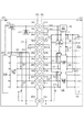
次に、図3を用いて、カメラ本体100にレンズ装置200を装着した場合について説明する。図3は、カメラ本体100にレンズ装置200が接続された状態での回路構成を示すブロック図である。レンズ装置200とカメラ本体100は、マウント部150およびマウント部250に設けられた複数の電気接点のうちの一部が形成する通信路を介して通信可能となっている。レンズ装置200とカメラ本体100は後述する第1の通信、第2の通信、第3の通信を行うことができる。
Next, the case where the
カメラ制御手段としてのカメラ制御部101は、マウント部150に設けられた電気接点の出力を制御したり、電気接点に入力された信号を処理したりすることで、カメラ本体100に装着されたアクセサリ装置と行われる通信を制御する。
The
カメラ電源部103は、カメラ本体100の各部およびカメラ本体100に装着されたアクセサリ装置の動作に用いられる電源である。カメラ電源部103は複数の異なる電圧を生成し、カメラ本体100の各部またはカメラ本体100に装着されたアクセサリ装置に各電圧の電源を供給する。
The camera
電源切り替え部104は、第1通信用I/F(インターフェース)部102aへ電源を供給する。電源切り替え部104には電源部103から電圧値の異なる2つの電源が供給されており、カメラ制御部101の制御の下で第1通信用I/F(インターフェース)部102aへ供給する電源を切り替え可能である。
The power
レンズ制御手段としてのレンズ制御部201は、マウント部250に設けられた電気接点の出力を制御したり、電気接点に入力された信号を処理したりすることで、カメラ本体100とレンズ装置200の間で行われる通信を制御する。
The
レンズ電源部203は、カメラ本体100から供給された電源から所定の電圧の電源を生成し、レンズ制御部201およびレンズ側通信用I/F部202に供給する。
The lens
電気接点1001および電気接点2001は、主にカメラ本体100とレンズ装置200との間で行われる通信の制御に用いられる電力(通信電力)をカメラ本体100の電源部103からレンズ装置200に供給するために用いられる端子である。以下、電気接点1001および電気接点2001をVDD端子1001およびVDD端子2001とも称する。本実施形態において、VDD端子1001によってレンズ装置200に供給される電力の電圧(以下、VDD電圧と称する)は5.0Vである。
The
電気接点(第1のカメラ側電気接点。第1の電気接点とも称する)1002および電気接点2002は主にモータ等の駆動系の動作に用いられる電力(駆動電力)をカメラ本体100からレンズ装置200に供給するために用いられる端子である。以下、電気接点1002および電気接点2002をVBAT端子1002およびVBAT端子2002とも称する。本実施形態において、VBAT端子1002によってレンズ装置200に供給される電力の電圧(以下、VBAT電圧と称する)は4.5Vである。VBAT電圧は第3の電圧に相当する。また、VDD端子とVBAT端子を総称して電源系端子とも称する。
The electrical contacts (first camera side electrical contacts; also referred to as first electrical contacts) 1002 and the
電気接点1012および電気接点2012は、カメラ本体100とレンズ装置200の通信制御系回路をグラウンド(グラウンドレベル)に接続する端子である。つまり、VDD端子に対応した接地端子である。以下、電気接点1012および電気接点2012をDGND端子1012およびDGND端子2012とも称する。
The
電気接点(第2のカメラ側電気接点。第2の電気接点とも称する)1004および電気接点2004は、カメラ本体100とレンズ装置200に設けられたモータ等を含む駆動系回路をグラウンド(グラウンドレベル)に接続するための端子である。つまり、VBAT端子に対応した接地端子である。以下、電気接点1004および電気接点2004をPGND端子1004およびPGND端子2004とも称する。また、DGND端子とPGND端子を総称してグラウンド端子とも称する。
The electrical contacts (second camera side electrical contacts; also referred to as second electrical contacts) 1004 and the
電気接点1005および電気接点2005は、カメラ本体100にレンズ装置が装着されたことを検出するための端子である。カメラ制御部101は、電気接点1005の電圧レベルに応じてカメラ本体100にレンズ装置の着脱を検出する。カメラ制御部101がレンズ装置の装着を検出すると、VDD端子1001およびVBAT端子1002を介してレンズ装置への電源供給を開始する。以下、電気接点1005および電気接点2005をMIF端子1005およびMIF端子2005とも称する。
The
電気接点(第3のカメラ側電気接点。第3の電気接点とも称する)1003および電気接点(第1のレンズ側電気接点。第4の電気接点とも称する)2003は、カメラ本体100に装着されたアクセサリ装置の種類を判別するための端子である。電気接点1003は、カメラ本体100内において、カメラ制御部101に供給される電源と同電圧に抵抗(第1の抵抗)125を介してプルアップされている。また、電気接点2003は、レンズ装置200内において抵抗222を介してグラウンド(DGND)にプルダウンされている。抵抗222は、レンズ装置200と同一の種類のレンズ装置に共通して定められた抵抗値を有する。このため、電気接点2003は電気接点1003と接続することで、電気接点1003の電圧をレンズ装置200の種類に対応した電圧に変化させることができる。カメラ制御部101は、電気接点1003の電圧値を検出し、検出された電圧値に基づいてカメラ本体100に装着されたアクセサリ装置の種類を判別する。すなわち、カメラ制御部101は装着されたアクセサリ装置の種類を判別する判別手段としても機能する。また、カメラ制御部101は、電源切り替え部104を制御してカメラ本体100に装着されたアクセサリ装置の種類に応じて電源切り替え部104によって第1通信用I/F部102aに供給される電源を切り替える。これによって、カメラ本体100とカメラ本体100に装着されたアクセサリ装置は適切な通信電圧で通信できる。以下、電気接点1003および電気接点2003をTYPE端子1003およびTYPE端子2003とも称する。
The electrical contacts (third camera side electrical contacts; also referred to as third electrical contacts) 1003 and the electrical contacts (first lens side electrical contacts; also referred to as fourth electrical contacts) 2003 are mounted on the
電気接点1006乃至1008および電気接点2006乃至2008は、後述する第1の通信に用いられる端子である。電気接点1006乃至1008の入出力は第1通信用I/F部102aを介してカメラ制御部101によって制御される。電気接点2006乃至2008の入出力は、レンズ側通信用I/F部202を介してレンズ制御部201によって制御される。
The
電気接点1008および電気接点2008は、第1の通信に用いられるクロック信号をカメラ本体100からレンズ装置200に出力可能な端子である。また、電気接点1008および電気接点2008はレンズ装置200がカメラ本体100に対して通信待機要求を通知するためにも用いられる。以下、電気接点1008および電気接点2008をLCLK端子1008およびLCLK端子2008とも称する。LCLK端子1008はカメラ本体100内で抵抗120を介して第1通信用I/F部102aのインターフェース電圧と同電位にプルアップされている。また、LCLK端子2008はレンズ装置200内で抵抗220を介してレンズ側通信用I/F部202のインターフェース電圧と同電位にプルアップされている。
The
電気接点1006および電気接点2006は、第1の通信によってカメラ本体100からレンズ装置200にデータを送信可能な端子である。以下、電気接点1006および電気接点2006をDCL端子1006およびDCL端子2006とも称する。DCL端子2006はレンズ装置200内で抵抗221を介してレンズ側通信用I/F部202のインターフェース電圧と同電位にプルアップされている。
The
電気接点1007および電気接点2007は、第1の通信によってレンズ装置200からカメラ本体100にデータを送信可能な端子である。以下、電気接点1007および電気接点2007をDLC端子1007およびDLC端子2007とも称する。DLC端子1007はカメラ本体100内で抵抗121を介して第1通信用I/F部102aのインターフェース電圧と同電位にプルアップされている。
The
以下では、第1の通信に用いられるLCLK端子1008、DCL端子1006、DLC端子1007を第1のカメラ側電気接点群とも称する。また、LCLK端子2008、DCL端子2006、DLC端子2007を第1のレンズ側電気接点群とも称する。
Hereinafter, the
電気接点1009および電気接点2009は後述する第2の通信に用いられる。電気接点1009および電気接点2009は、第2の通信によってレンズ装置200からカメラ本体100にデータを送信可能な端子である。以下、電気接点1009および電気接点2009をDLC2端子1009およびDLC2端子2009とも称する。DLC2端子1009はカメラ本体100内で抵抗122を介してDGND端子と同電位にプルダウンされている。
The
電気接点1010、1011および電気接点2010、2011は、後述する第3の通信に用いられる端子である。
The
電気接点1010および電気接点2010は、カメラ本体100とレンズ装置200の間で第3の通信によって双方向にデータを送受信可能な端子である。以下、電気接点1010および電気接点2010をDCA端子1010およびDCA端子2010とも称する。DCA端子1010はカメラ本体100内で抵抗124を介して第2・第3通信用I/F部102bのインターフェース電圧と同電位にプルアップされている。また、DCA端子1010はCMOSタイプの入出力インターフェースを介してカメラ制御部101に接続されている。同様に、DCA端子2010はCMOSタイプの入出力インターフェースを介してレンズ制御部201に接続されている。これによって、カメラ制御部101およびレンズ制御部201は、DCA端子1010および2010を用いて高速なデータの送受信を行うことができる。
The
電気接点1011および電気接点2011は、カメラ本体100とレンズ装置200の間で第3の通信に関する後述する所定のタイミングを通知するために用いられる端子である。以下、電気接点1011および電気接点2011をCS端子1011およびCS端子2011とも称する。CS端子1011はカメラ本体100内で抵抗123を介して第2・第3通信用I/F部102bのインターフェース電圧と同電位にプルアップされている。また、CS端子2011はレンズ装置200内で抵抗224を介してレンズ側通信用I/F部202のインターフェース電圧と同電位にプルアップされている。また、CS端子1011はオープンタイプの出力インターフェースを介してカメラ制御部101に接続されている。同様に、CS端子2011はオープンタイプの出力インターフェースを介してレンズ制御部201に接続されている。ここで、オープンタイプの出力インターフェースとは、オープンドレインまたはオープンコレクタである出力インターフェースを言う。
The
本実施形態において、カメラ本体100にレンズ装置200が装着された場合、第1通信用I/F部102aおよび第2・第3通信用I/F部102bのインターフェース電圧は3.0V(第1の電圧)に設定される。また、レンズ側通信用I/F部202のインターフェース電圧は3.0V(第1の電圧)に設定される。以下、LCLK端子、DCL端子、DLC端子、DLC2端子、CS端子、DCA端子を総称して通信系端子とも称する。
In the present embodiment, when the
次に、図4(a)、(b)を用いて、マウント部150およびマウント部250のカメラ側接点保持部154およびアクセサリ側接点保持部254の形状について述べる。
Next, the shapes of the camera side
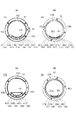
図4(a)は、カメラ本体100にレンズ装置200が装着された状態でのカメラ側接点保持部154およびアクセサリ側接点保持部254を光軸と垂直な方向から見た場合の概略図である。図4(b)は、カメラ本体100にレンズ装置200が完全に装着されていない状態でのカメラ側接点保持部154およびアクセサリ側接点保持部254を光軸と垂直な方向から見た場合の概略図である。図4(a)、(b)にはカメラ側接点保持部154およびアクセサリ側接点保持部254をそれぞれ平面に示している。ただし実際には、カメラ側接点保持部154およびアクセサリ側接点保持部254のそれぞれの形状はマウント部150およびマウント部250の周方向に沿って湾曲している。また、図4(a)、(b)において、カメラ本体100の電気接点をピン、レンズ装置200の電気接点を接片としているが、カメラ本体100の電気接点を接片、レンズ装置200の電気接点をピンとしても良い。
FIG. 4A is a schematic view of the camera side
図4(a)に示す矢印Aは、カメラ本体100からレンズ装置200を取り外す際の、カメラ本体100に対するレンズ装置200の移動方向(回転方向)を示している。レンズ装置200を取り外す際、例えばVDD端子2001はVBAT端子1002に接触した後にTYPE端子1003に接触する。
Arrow A shown in FIG. 4A indicates the moving direction (rotational direction) of the
また、図4(b)に示す矢印Bは、カメラ本体100にレンズ装置200を装着する際のカメラ本体100に対するレンズ装置200の移動方向(回転方向)を示している。レンズ装置200を装着する際、例えばVDD端子2001はVBAT端子1002に接触した後にVDD端子1001に接続される。
Further, an arrow B shown in FIG. 4B indicates the moving direction (rotational direction) of the
また、図4に示すように、カメラ側接点保持部154およびアクセサリ側接点保持部254は光軸方向に段差のある形状となっている。電気接点1001乃至1004と電気接点1005乃至1012は異なる段に設けられている。同様に、電気接点2001乃至2004と電気接点2005乃至2012は異なる段に設けられている。これにより、カメラ本体100にレンズ装置200を着脱する際に、電気接点2001乃至2004と電気接点1005乃至1012とを接触させないようにすることができる。したがって、カメラ本体100にレンズ装置200を着脱する際の電気接点の摩耗量を低減させることができる。
Further, as shown in FIG. 4, the camera side
さらに、本実施形態のカメラ本体100では、電気接点数が少ない方の段に電源系端子を設けている。同様に、本実施形態のレンズ装置200では、電気接点数が少ない方の段に電源系端子を設けている。これによって、カメラ本体100にレンズ装置200を着脱する際の電源系端子の摩耗量をより低減させ、接触インピーダンスの上昇を抑えることができる。結果として、長期間にわたって安定した電源供給を行うことができる。
Furthermore, in the
なお、安定した電源供給のためには、グラウンド端子も電気接点数が少ない方の段に設けることが好ましい。 In addition, in order to supply a stable power supply, it is preferable to provide a ground terminal also in the stage having a smaller number of electrical contacts.
一方、内部回路に対する静電気の影響を低減するためには、DGND端子1012およびDGND端子2012はマウント部150およびマウント部250の金属部分に接触させることが好ましい。この場合、マウント部150の加工を容易にするために、DGND端子1012を電気接点1001乃至1012の配列において端に配置することが好ましい。同様に、マウント部250の加工を容易にするために、DGND端子2012を電気接点2001乃至2012の配列において端に配置することが好ましい。
On the other hand, in order to reduce the influence of static electricity on the internal circuit, it is preferable that the
本実施形態ではこれらを鑑みて、PGND端子1004は保持している電気接点数が少ない方の段に設け、DGND端子1012は電気接点1001乃至1012の配列における端に設けている。同様に、PGND端子2004を保持している電気接点数が少ない方の段に設け、DGND端子2012を電気接点2001乃至2012の配列における端に設けている。
In the present embodiment, in view of these, the
次に、カメラ側接点保持部154およびアクセサリ側接点保持部254における電気接点の並び順について説明する。
Next, the order of arrangement of the electrical contacts in the camera side
本実施形態において、カメラ側接点保持部154の電気接点数が少ない方の段にはレンズ装置200の装着方向(図4(b)の矢印Bの方向)に順に、PGND端子1004、TYPE端子1003、VBAT端子1002、VDD端子1001が配置されている。同様に、アクセサリ側接点保持部254の電気接点数が少ない方の段には、レンズ装置200の装着方向(図4(b)の矢印Bの方向)に順に、PGND端子2004、TYPE端子2003、VBAT端子2002、VDD端子2001が配置されている。
In the present embodiment, the
導電性の異物がカメラ側接点保持部154およびアクセサリ側接点保持部254の間に挟まったり、電気接点が変形したりすると、隣接した電気接点同士がショートしてしまう場合がある。特に、電源系端子(VDD端子、VBAT端子)とグラウンド端子(PGND端子)がショートした場合、電源回路に大電流が流れ得る。これに対して、電源系端子とグラウンド端子の間に他の電気接点を設けることで、ショートによる電源回路への影響を低減できる。
When the conductive foreign matter is caught between the camera side
なお、電源系端子とグラウンド端子の間に設ける端子はカメラ本体100およびレンズ装置200の動作中に信号レベルが略一定である端子であることが好ましい。通常、電源系端子に隣接する端子とカメラ制御部101の間には、ショートした際にカメラ本体100の内部回路を保護するための保護素子が設けられる。仮に電源系端子とグラウンド端子の間にカメラ本体100およびレンズ装置200の動作中に信号レベルが変化する端子(通信系端子)を設ける場合、該端子の配線容量は保護素子によって増加してしまう。そのため、該端子を介して送信または受信される信号波形に影響を及ぼし得る。一方、カメラ本体100およびレンズ装置200の動作中に信号レベルが略一定である端子であれば、保護素子を設けることによる影響が少ない。動作中の信号レベルが略一定である端子としてはTYPE端子とMIF端子があるが、MIF端子は後述のように電気接点数が多い方の段の端に設けることが好ましいため、電源系端子とグラウンド端子の間にはTYPE端子を設けることが好ましい。なお、本実施形態では、TYPE端子1003とカメラ制御部101の間には、保護素子としての抵抗(第2の抵抗)126が設けられている。抵抗126の抵抗値は、抵抗125の抵抗値よりも小さい。
The terminal provided between the power supply system terminal and the ground terminal is preferably a terminal whose signal level is substantially constant during the operation of the
また、本実施形態において、MIF端子1005は、カメラ側接点保持部154の電気接点数の多い方の段における電気接点数が少ない方の段に最も近い位置に配置されている。これに対応して、MIF端子2005は、アクセサリ側接点保持部254の電気接点数が多い方の段における電気接点数が少ない方の段に最も近い位置に配置されている。
Further, in the present embodiment, the
このような位置にMIF端子1005を配置することで、カメラ本体100にレンズ装置200を着脱する際にMIF端子1005と接触する電気接点をMIF端子2005のみとすることができる。これによって、MIF端子1005の摩耗を低減できる。これによって、MIF端子1005の接触不良を生じにくくすることができ、レンズ装置の装着を適切に検出することができる。
By disposing the
なお、カメラ本体100にレンズ装置200を着脱する際、MIF端子2005は電気接点1006乃至1012と接触するため、MIF端子2005は摺動による摩耗量の多い位置に配置されていると言える。しかし、図1に示すようにカメラ本体100には複数の種類のカメラアクセサリが装着されるため、レンズ装置200の電気接点の摩耗量はカメラ本体100に比べて少ない。このため、本実施形態ではカメラ本体100のMIF端子1005の摩耗量が少なくなるように電気接点を配列している。
When the
さらに、カメラ本体100にレンズ装置200を装着する際にMIF端子1005に他の電気接点が接触すると、MIF端子1005の電圧レベルが変化し、カメラ制御部101がレンズ装置の装着を誤検出してしまうおそれがある。レンズ装置200の装着が完了していないにも関わらずレンズ装置200の装着を誤検出してしまうと、電源系端子による電源供給が開始されてしまい、レンズ装置200の誤動作やレンズ装置200の内部回路への影響を及ぼし得る。これに対して、本実施形態のようにMIF端子1005を配置することで、MIF端子同士が接続される前に(すなわちレンズ装置200の装着が完了する前に)電源供給が開始されることを抑制できる。
Furthermore, when another electric contact contacts the
なお、レンズ装置200のMIF端子2005のマウント部250の周方向の長さは、他の電気接点よりも短いことが好ましい。これによって、カメラ本体100にレンズ装置200を装着する際、複数の電気接点の中でMIF端子1005が最後に接続されるようにすることができる。この場合、他の電気接点同士の接続が完了した後にカメラ本体100からレンズ装置200への電源供給を行わせることができる。また、カメラ本体100からレンズ装置200を取り外す際、複数の電気接点の中でMIF端子1005が最初に切断されるようにすることができる。この場合、カメラ本体100からレンズ装置200を取り外す際、即座にカメラ本体100からレンズ装置200への電源供給を停止させることができる。なお、MIF端子2005のマウント部250の周方向の長さとしては、他の電気接点よりも中心角1°に相当する分だけ短ければ十分である。
The circumferential length of the
また本実施形態において、通信系端子の並び順は、各端子の役割を鑑みて適切に定められている。具体的には、DGND端子1012に隣接してCS端子1011を配置し、CS端子1011を挟んでDGND端子1012とは反対側にDCA端子1010を配置している。同様に、DGND端子2012に隣接してCS端子2011を配置し、CS端子2011を挟んでDGND端子2012とは反対側にDCA端子2010を配置している。これによって、後述のように、第3の通信の通信速度を高速にしつつ、意図しない電気接点同士が接続された際のカメラ本体100およびレンズ装置200への電気的な影響を低減している。
In the present embodiment, the arrangement order of the communication system terminals is appropriately determined in consideration of the role of each terminal. Specifically, the
また、DCA端子1010とLCLK端子1008の間には第2の通信に用いられるDLC2端子1009が設けられている。同様に、DCA端子2010とLCLK端子2008の間には第2の通信に用いられるDLC2端子2009を設けている。これによって、後述のように、意図しない電気接点同士が接続された際のカメラ本体100およびレンズ装置200への電気的な影響を低減している。
In addition, a
さらに、第1のカメラ側電気接点群を、DLC2端子1009、DCA端子1010、CS端子1011のいずれよりもMIF端子1005に近い位置に配置している。すなわち、アクセサリ装置の着脱によって第1のカメラ側電気接点群の各電気接点が受ける摺動量はDLC2端子1009、DCA端子1010、CS端子1011のいずれよりも少ない。これによって、後述のように、電気接点の摩耗による通信不良の発生を低減している。
Furthermore, the first camera side electric contact group is disposed at a position closer to the
次に、図5を用いて、カメラ本体100に中間アクセサリ装置500を介してレンズ装置200を装着する場合について説明する。中間アクセサリ装置500はカメラ本体100と第3の通信を行うことができる。
Next, the case of mounting the
図5は、カメラ本体100に、中間アクセサリ装置500を介してレンズ装置200が装着されている場合のブロック図である。前述のように、中間アクセサリ装置500はマウント部550aと550bを備える。また、中間アクセサリ装置500は、カメラ本体100との通信を制御したり、中間アクセサリ装置500に設けられた操作部材(不図示)の操作に応じた処理を行ったりするアクセサリ制御部501を有する。操作部材の操作は、アダプタ操作入力部502を介してアクセサリ制御部501に伝えられる。なお、操作部材の一例としては、絞り値の設定が可能なファンクションリングを挙げることができる。
FIG. 5 is a block diagram of the case where the
マウント部550aは、前述したレンズ装置200のマウント部250と同様である。また、マウント部550bは、前述したカメラ本体100のマウント部150と同様である。マウント部550aに設けられた電気接点2001乃至2012は、中間アクセサリ装置500内においてマウント部550bに設けられた電気接点1001乃至1012まで配線されている。
The
なお、中間アクセサリ装置500内においてVDD端子2001はアクセサリ電源部503にも接続されており、中間アクセサリ装置500にも電源を供給するように構成されている。本実施形態では、アクセサリ電源部503は3.0Vの電源を生成してアクセサリ制御部501やアクセサリ操作入力部502に供給する。また、中間アクセサリ装置500内において第3の通信に用いられるDCA端子2010およびCS端子2011はアクセサリ制御部501にも接続されており、中間アクセサリ装置500とカメラ本体100は第3の通信を行なうことができる。
In the
カメラ本体100に中間アクセサリ装置500を介してレンズ装置200が装着された場合、第1通信用I/F部102aおよび第2・第3通信用I/F部102bのインターフェース電圧は3.0Vに設定される。また、レンズ側通信用I/F部202のインターフェース電圧は3.0Vに設定される。
When the
以上では、カメラ本体100にレンズ装置200を装着する場合について説明した。
In the above, the case where the
次に、図6を用いて、カメラ本体100にレンズ装置300を装着する場合について説明する。前述のように、レンズ装置300は従来例のレンズ装置であり、本実施形態のレンズ装置200とは異なる。レンズ装置300はカメラ本体と第2の通信、第3の通信を行うことはできないが、第1の通信を行うことができる。また、中間アクセサリ装置400はカメラ本体と第3の通信を行うことができる。
Next, the case where the
図6は、カメラ本体100に、中間アクセサリ装置400を介してレンズ装置300が装着されている場合のブロック図である。前述のように、中間アクセサリ装置400はマウント部450aと450bを備える。また、中間アクセサリ装置400は、カメラ本体100と通信したり、不図示の操作部材の操作に応じた処理を行ったりするアダプタ制御部401を有する。操作部材の操作は、アダプタ操作入力部402を介してアダプタ制御部401に伝えられる。
FIG. 6 is a block diagram of the case where the
マウント部450aは、前述したレンズ装置200のマウント部250と同様である。ただし、中間アクセサリ装置400の内部回路とレンズ装置200の内部回路は異なる。具体的には、第1の通信に用いられるDCL端子2006、DLC端子2007、LCLK端子2008は中間アクセサリ装置400内でアダプタ制御部401に接続されておらず、マウント部450bの対応する電気接点までスルー配線されている。一方、第3の通信に用いられるDCA端子2010およびCS端子2011は中間アクセサリ装置400内でアダプタ制御部401に接続されている。これは、中間アクセサリ装置400はカメラ本体100と第1の通信を行わず第3の通信を行うためである。
The
また、第2の通信に用いられるDLC2端子2009は中間アクセサリ装置400内で抵抗を介してDGND端子2012と同レベルにプルダウンされている。これは、レンズ装置300とカメラ本体100は第2の通信を行わないためである。
Also, the
また、TYPE端子2003は中間アクセサリ装置400内で抵抗422を介してDGND端子2012と同レベルにプルダウンされている。抵抗422はレンズ装置200の抵抗222とは異なる抵抗値を有する。これによって、カメラ本体100に中間アクセサリ400を介してレンズ装置300が装着された場合とレンズ装置200が装着された場合とで、TYPE端子1003の電圧を互いに異ならせることができる。すなわち、中間アクセサリ装置400のTYPE端子は、カメラ本体100のTYPE端子1003と接続することで、電気接点1003の電圧をレンズ装置300の種類に対応した電圧に変化させる。
Further, the
次に、マウント部450bおよびマウント部350に設けられた電気接点について説明する。
Next, the electrical contacts provided on the
電気接点3001および電気接点4001は、駆動電力をカメラ本体100のVBAT端子1002からレンズ装置300に供給するために用いられる端子である。中間アクセサリ装置400においてVBAT端子2002は電気接点4001までスルー配線されている。以下、電気接点3001および電気接点4001をVBAT端子3001およびVBAT端子4001とも称する。なお、本実施形態において、VBAT端子1002によってレンズ装置300に供給される電力の電圧は4.5Vである。
The
電気接点3004および電気接点4004は、カメラ本体100のVDD端子1001からレンズ装置300に通信電力を供給するために用いられる端子である。中間アクセサリ装置400においてVDD端子2001は電気接点4004までスルー配線されると共に、中間アクセサリ装置400内のアダプタ電源部403にも接続されている。アダプタ電源部403はアダプタ制御部401およびアダプタ操作入力部に供給する電源として3.0Vの電源を生成する。以下、電気接点3004および電気接点4004をVDD端子3004およびVDD端子4004とも称する。なお、本実施形態において、VDD端子1001によってレンズ装置200に供給される電力の電圧は5.0Vである。
The
電気接点3003および電気接点4003は、カメラ本体100とレンズ装置300の駆動系をグラウンドに接続するための端子である。つまり、VBAT端子に対応した接地端子である。中間アクセサリ装置400においてPGND端子2004は電気接点4003までスルー配線されている。以下、電気接点3003および電気接点4003をPGND端子3003およびPGND端子4003とも称する。
The
電気接点3008および電気接点4008は、カメラ本体100とレンズ装置300の通信制御系をグラウンドに接続するための端子である。つまり、VDD端子に対応した接地端子である。中間アクセサリ装置400においてDGND端子2012は電気接点4008までスルー配線されている。以下、電気接点3008および電気接点4008をDGND端子3008およびDGND端子4008とも称する。
The
電気接点3002および電気接点4002は、カメラ本体100に中間アクセサリ装置400を介してレンズ装置300が装着されたことを検出するために用いられる端子である。カメラ制御部101はレンズ装置300の装着を検出すると、レンズ装置300への電源供給を開始する。中間アクセサリ装置400においてMIF端子2005は電気接点4002までスルー配線されている。以下、電気接点3002および電気接点4002をMIF端子3002およびMIF端子4002とも称する。
The
電気接点3005乃至3007および電気接点4005乃至4007は、後述する第1の通信に用いられる端子である。電気接点3005乃至3007の入出力はレンズ側通信用I/F部302を介してレンズ制御部301によって制御される。以下、電気接点3005、3006、3007をDCL端子3005、DLC端子3006、LCLK端子3007とも称する。また、電気接点4005、4006、4007をDCL端子4005、DLC端子4006、LCLK端子4007とも称する。
The
中間アクセサリ装置400を介してレンズ装置300が装着されている場合、第1通信用I/F部102aおよびレンズ側通信用I/F部302のインターフェース電圧はVDD端子から供給される電圧と同じ電圧である5.0V(第2の電圧)に設定される。第2の電圧は第1の電圧とは異なる電圧である。
When the
一方、第2・第3通信用I/F部102bのインターフェース電圧は3.0Vに設定される。すなわち、カメラ本体100に中間アクセサリ装置400を介してレンズ装置300が装着されている場合、第1の通信の通信電圧と第3の通信の通信電圧は互いに異なる。なお、後述のように、カメラ本体100に中間アクセサリ装置400を介してレンズ装置300が装着されている場合、第2の通信は行われない。
On the other hand, the interface voltage of the second and third communication I /
以上、カメラ本体100およびカメラ本体100に装着可能なアクセサリ装置の構成について説明した。次に、TYPE端子1003の機能について詳しく説明する。
The configurations of the
以下では、TYPE端子1003がカメラ本体内でプルアップされる電源電圧は3.3Vであるとする。また、抵抗125の抵抗値は100kΩ、抵抗126の抵抗値は1kΩ、抵抗222の抵抗値は33kΩ、抵抗422の抵抗値は300kΩであるとする。また、TYPE_IN端子に入力される電圧値は、不図示のAD変換器により10bitの分解能でデジタル信号に変換されるものとする。
In the following, it is assumed that the power supply voltage at which the
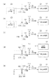
図7(a)は、カメラ本体100にレンズ装置200が装着された状態におけるTYPE端子1003の周辺回路を図示したものである。この場合、カメラ制御部101のTYPE_IN端子に入力される値は、電源電圧(3.3V)を抵抗125と抵抗222で分圧した電圧値をAD変換した値であり、おおよそ「0x0103」となる。
FIG. 7A illustrates a peripheral circuit of the
また、図7(b)はカメラ本体100に中間アクセサリ装置400を介してレンズ装置300が装着された状態におけるTYPE端子1003の周辺回路を図示したものである。この場合、カメラ制御部101のTYPE_IN端子に入力される値は、電源電圧(3.3V)を抵抗125と抵抗422で分圧した電圧値をAD変換した値であり、おおよそ「0x0300」となる。
Further, FIG. 7B illustrates a peripheral circuit of the
このように、中間アクセサリ装置400の抵抗422の抵抗値とレンズ装置200の抵抗222の抵抗値を異ならせることで、カメラ本体100に装着されたアクセサリ装置の種類に応じてTYPE_IN端子に入力される値を異ならせることができる。このため、カメラ制御部101はTYPE_IN端子の入力値を用いてカメラ本体100に装着されたアクセサリ装置の種類を判別することができる。
As described above, by making the resistance value of the
しかしながら、TYPE端子1003とTYPE端子2003の接続状態に何らかの異常が生じた場合、TYPE_IN端子に本来想定されない値が入力される場合がある。アクセサリ装置の装着状態に何らかの異常があるにも関わらず、カメラ制御部101がカメラ本体100に何らかのアクセサリ装置が装着されていると判定してしまうと、アクセサリ装置に定格外の電圧を印加してしまうおそれがあるため好ましくない。そこで、図7(c)、(d)、(e)を用いて、TYPE端子1003とTYPE端子2003の接続状態に何らかの異常が生じた場合について考える。
However, when an abnormality occurs in the connection state of the
図7(c)は、カメラ本体100にアクセサリ装置の装着が完了しているにも関わらず、接触不良などによりTYPE端子1003とTYPE端子2003が接触しなかった場合のTYPE端子1003の周辺回路を図示したものである。この場合、TYPE_IN端子に入力される電圧値はカメラ本体100内の抵抗125(100kΩ)のみで決まり、AD変換後の値はおおよそ「0x03FF」となる。
FIG. 7C shows a peripheral circuit of the
図7(d)はTYPE端子1003とVBAT端子1002がショートした場合のTYPE端子1003の周辺回路を図示したものである。ここで、カメラ本体100に装着されたアクセサリ装置の種類の判定をVBAT端子1002およびVBAT端子2002への電源供給より前に行う場合について考える。電源供給を行っていないときのVBAT端子1002およびVBAT端子2002の電圧がPGND端子と同じである場合、TYPE端子1003とVBAT端子1002がショートするとTYPE端子1003の電圧はPGND端子の電圧と略等しくなる。このとき、TYPE_IN端子に入力される値は、カメラ本体100内の抵抗125(100kΩ)と抵抗126(1kΩ)の分圧比で決まり、おおよそ「0x000A」となる。
FIG. 7D illustrates a peripheral circuit of the
次に、カメラ本体100に装着されたアクセサリ装置の種類の判定をVBAT端子1002およびVBAT端子2002への電源供給より後に行う場合について考える。この場合、TYPE端子1003とVBAT端子1002がショートしてしまうと、VBAT電圧(本実施形態では4.5V)がTYPE端子1003に印加されることになる。このとき、TYPE_IN端子に入力される値はおおよそ「0x03FF」となる。
Next, consider the case where the type of the accessory device attached to the
図7(e)はTYPE端子1003とPGND端子1004がショートした場合のTYPE端子1003の周辺回路を図示したものである。TYPE端子1003とPGND端子1004がショートした場合、TYPE端子1003の電圧はPGND端子1004の電圧(VBAT電圧の基準電位(グラウンドレベル)の電圧)と略等しくなる。このとき、TYPE_IN端子に入力される値はカメラ本体100内の抵抗125(100kΩ)と抵抗126(1kΩ)との分圧比で決まり、おおよそ「0x000A」となる。
FIG. 7E shows a peripheral circuit of the
以上説明したように、TYPE端子1003とTYPE端子2003の接続状態に何らかの異常が生じた場合、TYPE端子1003の電圧は、VBAT電圧またはPGND端子1004の電圧と略等しくなる。そこで本実施形態では、カメラ本体100に適切にレンズ装置が装着されたと判定されるTYPE端子1003の電圧の範囲として、VBAT電圧およびPGND端子1004の電圧を含まない電圧範囲を設定している。表1に、本実施形態におけるTYPE_IN端子の入力値とカメラ制御部101による装着状況の判別結果の対応表を示す。
As described above, when an abnormality occurs in the connection state of the

表1に示すように、TYPE_IN端子の入力値が「0x0080〜0x017F」の範囲内であれば、カメラ制御部101はカメラ本体100にレンズ装置200が装着されていると判定するようにしている。「0x0080〜0x017F」は、TYPE端子1003の電圧がVBAT電圧およびPGND端子1004の電圧を含まない電圧範囲(第1の電圧範囲)の電圧である場合に対応したTYPE_IN端子の入力値である。したがって、カメラ本体100にレンズ装置200が適切に装着された場合にのみ、カメラ制御部101はカメラ本体100にレンズ装置200が装着されたと判定することができる。レンズ装置200が装着されたと判定された場合、カメラ制御部101は通信電圧3.0Vでレンズ装置200と通信を行なう。
As shown in Table 1, when the input value of the TYPE_IN terminal is in the range of “0x0080 to 0x017F”, the
同様に、TYPE_IN端子の入力値が「0x0280〜0x037F」の範囲内であれば、カメラ制御部101はカメラ本体100にレンズ装置300が装着されていると判定するようにしている。「0x0280〜0x037F」は、TYPE端子1003の電圧が第1の電圧範囲、VBAT電圧、PGND端子1004の電圧を含まない電圧範囲(第2の電圧範囲)の電圧である場合に対応したTYPE_IN端子の入力値である。したがって、カメラ本体100にレンズ装置300が適切に装着された場合にのみ、カメラ制御部101はカメラ本体100にレンズ装置300が装着されたと判定することができる。レンズ装置300が装着されたと判定された場合、カメラ制御部101は通信電圧5.0Vでレンズ装置300と通信を行なう。
Similarly, when the input value of the TYPE_IN terminal is in the range of “0x0280 to 0x037F”, the
以上のように、TYPE_IN端子の入力値とカメラ制御部101による装着状況の判別結果の対応関係を予め定めておくことで、装着されたレンズ装置の種類を適切に判別することができる。
As described above, by predetermining the correspondence between the input value of the TYPE_IN terminal and the determination result of the mounting condition by the
なお、TYPE_IN端子の入力値が「0x0000〜0x007F」の範囲内である場合、カメラ制御部101はカメラ本体100とアクセサリ装置の装着状態に何らかの異常が生じていると判定する。「0x0000〜0x007F」は、TYPE端子1003の電圧がPGND端子1004の電圧を含み第1の電圧範囲および第2の電圧範囲を含まない第4の電圧範囲である場合に対応したTYPE_IN端子の入力値である。この場合、カメラ制御部101はカメラ本体に装着されたレンズ装置と通信を行なわない。これによって、TYPE端子の接続状態に異常が生じた場合に、アクセサリ装置に定格外の電圧を印加してしまうことを防ぐことができる。
When the input value of the TYPE_IN terminal is in the range of “0x0000 to 0x007F”, the
また、TYPE_IN端子の入力値が「0x0380〜0x03FF」の範囲内である場合、カメラ制御部101はカメラ本体100とアクセサリ装置の装着状態に何らかの異常が生じていると判定する。「0x0380〜0x03FF」は、TYPE端子1003の電圧がVBAT電圧を含み第1の電圧範囲および第2の電圧範囲を含まない第3の電圧範囲である場合に対応したTYPE_IN端子の入力値である。この場合、カメラ制御部101はカメラ本体に装着されたレンズ装置と通信を行なわない。これによって、TYPE端子の接続状態に異常が生じた場合に、アクセサリ装置に定格外の電圧を印加してしまうことを防ぐことができる。
When the input value of the TYPE_IN terminal is in the range of “0x3800 to 0x03FF”, the
次に、図8のフローチャートを用いて、カメラ本体100の動作フローについて説明する。本フローは、カメラ制御部101に格納されているコンピュータプログラムに従って行われる。図8のフローチャートは、カメラ本体100の不図示の電源スイッチの操作によりカメラ本体100の電源をONにした状態からスタートする。なお、フローチャートにおいてSはステップを表す。
Next, the operation flow of the
まず、S601においてカメラ制御部101はMIF_IN端子の電圧値を取得し、不図示のRAM領域に記憶させる。
First, in step S601, the
次に、S602において、カメラ制御部101はS601で記憶させたMIF_IN端子の電圧値がLowレベルに相当するか否か判定する。MIF_IN端子の電圧値がLowレベルでない場合、カメラ本体100にはレンズ装置が装着されていない状態であるため、S601に戻る(S602のNo)。MIF_IN端子の電圧値がLowレベルである場合、カメラ本体100にレンズ装置が装着された状態であると判定し、S603に進む。
Next, in step S602, the
S603では、カメラ制御部101は、TYPE_INの電圧値を取得し、不図示のRAM領域に記憶させる。
In S603, the
S604では、S603で記憶させたTYPE_INの値が0x0080以上0x017F以下の範囲であるか否か判定する。S604がYesの場合、カメラ制御部101は装着されたレンズ装置がレンズ装置200であると判定する。この場合、S605に進む。
In S604, it is determined whether the value of TYPE_IN stored in S603 is in the range of 0x0080 or more and 0x017F or less. When S604 is Yes, the
S605では、第1通信用I/F部102aに供給される電源電圧が3.0Vとなるようにカメラ制御部101が電源切り替え部104を制御する。
In S605, the
その後、S606で電源部103によるVDD端子1001への電源供給を開始し、S607でレンズ装置200と第1の通信による通信を開始する。
After that, the power supply to the
一方、S604がNoだった場合、S608に進む。S608では、S603で記憶したTYPE_INの値が0x0180以上0x02FF以下の範囲であるか否か判定する。S608がYesの場合、カメラ制御部101は装着されたレンズ装置がレンズ装置300であると判定する。この場合、S609に進む。
On the other hand, when S604 is No, it progresses to S608. In S608, it is determined whether the value of TYPE_IN stored in S603 is in the range of 0x0180 or more and 0x02FF or less. If S608 is Yes, the
S609では、第1通信用I/F部102aに供給される電源電圧が5.0Vとなるようにカメラ制御部101が電源切り替え部104を制御する。
In step S609, the
その後、S610で電源部103によるVDD端子1001への電源供給を開始し、S611でレンズ装置300と第1の通信による通信を開始する。
After that, the power supply to the
一方、S608がNoだった場合、S612に進む。この場合、カメラ制御部101は装着されたアクセサリ装置がカメラ本体100では制御できないアクセサリ装置である、または、装着状態に異常が生じていると判定し、S613に進む。
On the other hand, when S608 is No, it progresses to S612. In this case, the
S613では、カメラ制御部101はアクセサリとの通信を行なわず、カメラ本体100に設けられた不図示の表示部に接続エラーであることを表示する。
In step S613, the
S614では、カメラ本体100の電源スイッチの操作によりカメラ本体100の電源がOFFにされたかどうかを判定する。電源スイッチがOFFにされたと判定した場合は電源OFFの処理を行う。そうでない場合は、S615に進む。
In step S614, it is determined whether the power of the
S615では、カメラ制御部101がMIF_IN端子の電圧値を読み込み、不図示のRAM領域に記憶する。
In S615, the
S616では、S615で記憶したMIF_INの電圧値がHighレベルに相当するか判定する。MIF_INの電圧値がHighの場合、カメラ本体100に装着されていたレンズ装置が取り外されたと判定する。一方、MIF_INの電圧値がLowレベルの場合は、レンズ装置が装着されたままであると判定して、S614に戻る。
In S616, it is determined whether the voltage value of MIF_IN stored in S615 corresponds to the High level. If the voltage value of MIF_IN is High, it is determined that the lens device mounted on the
S617では、カメラ制御部101はレンズ装置との通信を停止し、S618で電源部103によるVDD端子1001への電源供給を停止する。その後、S601に進む。
In step S617, the
次に、カメラ本体100に装着されたアクセサリ装置と、カメラ本体100との間で行われる通信について説明する。
Next, communication performed between the accessory device mounted on the
まず、第1の通信について説明する。第1の通信とは、カメラ本体100とカメラ本体100に装着されたレンズ装置との間で行われる通信の1つである。第1の通信は、LCLK端子、DCL端子、DLC端子を用いて行われる。また、第1の通信はクロック同期式の通信方式で行われる。なお、第1の通信は調歩同期式の通信方式で行っても良い。その場合、LCLK端子はデータ送信要求をカメラ本体100からレンズ装置に通知するための端子として用いられる。
First, the first communication will be described. The first communication is one of communication performed between the
レンズ装置200とレンズ装置300は、共に第1の通信に対応している。ただし、前述のように第1の通信の通信電圧はレンズ装置200とレンズ装置300で異なる。
The
カメラ本体100は、レンズ装置を制御するための制御コマンドを第1の通信によってレンズ装置に送信する。制御コマンドはレンズ装置の駆動部(不図示)を駆動させるためのコマンドを含む。なお、レンズ装置の駆動部としてはフォーカスレンズ、ズームレンズ、絞り羽を例示することができる。
The
第1の通信によって送信された制御コマンドを受信したレンズ装置は、命令に応じた動作を行う。また、レンズ装置は制御コマンドに応答して自身の状態に関する情報(状態情報)を第1の通信によってカメラ本体100へ送信する。ここで言う状態に関する情報とは、フォーカスレンズの位置、焦点距離、絞り値に関する情報を含む。
The lens apparatus having received the control command transmitted by the first communication performs an operation according to the command. Further, in response to the control command, the lens apparatus transmits information (state information) related to its own state to the
以上のように、第1の通信は、主としてレンズ装置を制御するために用いられる通信である。 As described above, the first communication is a communication that is mainly used to control the lens device.
次に、第2の通信について説明する。第2の通信とは、カメラ本体100とカメラ本体100に装着されたレンズ装置200との間で行われる通信の1つであり、DLC2端子1009および2009を用いて行われる非同期式の通信である。なお、レンズ装置300はDLC2端子を有さないため、カメラ本体100にレンズ装置300が装着された場合第2の通信は行われない。ゆえに、カメラ本体100にレンズ装置300が装着された場合、DLC2端子1009は使用されない。
Next, the second communication will be described. The second communication is one of the communication performed between the
第2の通信では、レンズ装置200が通信マスターとなり、レンズ装置200におけるフォーカスレンズの位置、ズームレンズの位置、絞り値、防振レンズの状態等の光学データをカメラ本体100に送信する。第2の通信によってレンズ装置200がカメラ本体100に送信するデータの種類や順番は、カメラ本体100から第1の通信によって指定される。
In the second communication, the
ここで、図9を用いて、第2の通信のフローについて説明する。図9のフローチャートは、撮像制御が開始されたタイミングからスタートする。なお、フローチャートにおけるSはステップを表す。 Here, the flow of the second communication will be described using FIG. The flowchart of FIG. 9 starts from the timing at which imaging control is started. In the flowchart, S represents a step.
S1401において、カメラ本体100は、第2の通信を開始することを要求する開始要求を、第1の通信によってレンズ装置200に送信する。S1401において送信される開始要求には、カメラ本体100が第2の通信でレンズ装置200から受信したいデータの種類と、受信する順番が予め登録されている登録通信コマンドが含まれている。
In S1401, the
S1411において、レンズ装置200はカメラ本体100から開始要求を受信する。S1412において、レンズ装置200は開始要求に含まれる登録通信コマンドで指定された種類のデータを指定された順番で生成する。
In S1411, the
S1413において、レンズ装置200はS1412で生成したデータをカメラ本体100に第2の通信によって送信する。すなわち、レンズ装置200は、S1412で生成したデータをカメラ本体100にDLC2端子2009を用いて送信する。
In S1413, the
カメラ本体100はS1402においてレンズ装置200から第2の通信によって送信されたデータを受信する。
The
S1402またはS1413の後に再び撮像制御が開始された場合、再び図9に示す制御を開始する。 If imaging control is started again after S1402 or S1413, control shown in FIG. 9 is started again.
このように、第2の通信の開始要求は第1の通信によって行われ、第2の通信によるレンズ装置200からカメラ本体100へのデータ送信は、DLC2端子2009を用いて行われる。よって、第1の通信に用いられる電気接点とは別にDLC2端子2009を設けて第2の通信を行うことにより、第1の通信で行う必要のある他の通信を妨げることなく、レンズ装置200からカメラ本体100へ光学データを送信することができる。
As described above, the request for starting the second communication is made by the first communication, and the data transmission from the
なお、第2の通信の開始要求は第1の通信によって行われるため、第1の通信が成立していない場合に第2の通信を行うことはできない。 In addition, since the start request of the second communication is performed by the first communication, the second communication can not be performed when the first communication is not established.
次に、第3の通信について説明する。第3の通信とは、レンズ装置200、中間アクセサリ装置400、中間アクセサリ装置500とカメラ本体100の間で行われる通信であり、DCA端子およびCS端子を用いて行われる非同期式の通信である。
Next, the third communication will be described. The third communication is communication performed between the
前述のように、レンズ装置300はDCA端子およびCS端子を有さないため、カメラ本体100に中間アクセサリ装置400を介してレンズ装置300が装着された場合、カメラ本体100とレンズ装置300は第3の通信を行わない。ただし、この場合カメラ本体100と中間アクセサリ装置400は第3の通信を行なっても良い。
As described above, since the
第3の通信において、通信マスターはカメラ本体100であり、通信スレーブはレンズ装置200、中間アクセサリ装置400、中間アクセサリ装置500である。なお、図5にはカメラ本体100とレンズ装置200の間に1つの中間アクセサリ装置500のみが装着されている場合を例示しているが、カメラ本体100とレンズ装置200に複数の中間アクセサリ装置が装着されることもある。したがって、第3の通信では、1つの通信マスターに対して複数の通信スレーブが直列に接続される場合がある。このため、第3の通信では、カメラ本体100が複数のスレーブに対して一斉に信号を送信するブロードキャスト通信モードと、特定のスレーブを指定して通信を行うP2Pモードとで通信を行なうことができる。
In the third communication, the communication master is the
第3の通信におけるブロードキャスト通信モードとP2Pモードにおいて、DCA端子は共にデータを送受信するための端子として機能する。一方、CS端子の機能はブロードキャスト通信モードとP2Pモードで異なる。以下では、カメラ本体100に中間アクセサリ装置500を介してレンズ装置200が装着されている場合を例にして、ブロードキャスト通信モードとP2PモードにおけるCS端子の機能について説明する。
In the broadcast communication mode and the P2P mode in the third communication, both DCA terminals function as terminals for transmitting and receiving data. On the other hand, the function of the CS terminal is different between the broadcast communication mode and the P2P mode. In the following, the function of the CS terminal in the broadcast communication mode and the P2P mode will be described by taking the case where the
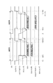
図10は、カメラ制御部101とレンズ制御部201とアクセサリ制御部501との間でやり取りされるブロードキャスト通信における通信制御タイミングを示している。カメラ制御部101、レンズ制御部201、アクセサリ制御部501のCS端子の出力をそれぞれCS(カメラ)、CS(レンズ)、CS(アクセサリ)と表している。また、カメラ制御部101、レンズ制御部201、アクセサリ制御部501のDCA端子の出力をそれぞれDCA(カメラ)、DCA(レンズ)、DCA(アクセサリ)と表している。また、CS端子が構成する信号線(CS信号線)の信号波形とDCA端子が構成する信号線(DCA信号線)の信号波形を、それぞれCS、DCAと表している。図10は、カメラ制御部101からレンズ制御部201およびアクセサリ制御部501へのブロードキャスト通信に応答する形でアクセサリ制御部501からカメラ制御部101およびレンズ制御部201へのブロードキャスト通信を行う場合を示している。
FIG. 10 illustrates communication control timing in broadcast communication exchanged among the
まず、図10に示した(1)のタイミングで、通信マスターであるカメラ制御部101は、ブロードキャスト通信を開始することを通信スレーブであるレンズ制御部201およびアクセサリ制御部501に通知するために、CS端子にLowを出力する。次に、図10に示した(2)のタイミングで、カメラ制御部101は送信するデータをDCA端子に出力する。
First, at the timing (1) shown in FIG. 10, the
図10の(3)のタイミングで、レンズ制御部201とアクセサリ制御部501はDCA端子から入力された信号のスタートビットSTを検出すると、CS端子へのLow出力を開始する。なお、この時点ではすでに(1)のタイミングでカメラ制御部101がCS端子へのLow出力を行っているので、CS信号線のレベルは変化しない。
At timing (3) in FIG. 10, when the
図10の(4)のタイミングで、送信するデータのストップビットSPまで出力が完了したら、カメラ制御部101は(5)のタイミングで、CS端子へのLow出力を解除する。一方、レンズ制御部201とアクセサリ制御部501はストップビットSPまで受信したら、受信したデータの解析および受信したデータに関する内部処理を行う。内部処理が完了し、次のデータを受信するための準備が整った場合、レンズ制御部201およびアクセサリ制御部501は、それぞれ(6)、(7)のタイミングで、CS端子へのLow出力を解除する。
When the output of the stop bit SP of the data to be transmitted is completed at the timing (4) in FIG. 10, the
このとき、受信したデータの解析および受信したデータに関する内部処理に要する時間は各制御部の処理能力に依って異なる。したがって、次の通信を適切に行うためには、各制御部は、他の全てのマイコンにおいて、受信したデータに関する内部処理が完了したタイミングを把握する必要がある。 At this time, the time required for the analysis of the received data and the internal processing for the received data varies depending on the processing capability of each control unit. Therefore, in order to appropriately perform the next communication, each control unit needs to grasp the timing at which the internal processing related to the received data is completed in all the other microcomputers.
本実施形態では、前述のとおりCS端子はオープンタイプの出力端子である。このため、CS信号線のレベルは、カメラ制御部101、レンズ制御部201、アクセサリ制御部501の全てがそれぞれのCS端子へのLow出力を解除した場合にHighとなる。すなわち、ブロードキャスト通信に関与する各制御部は、CS信号線のレベルがHighとなることを確認することで、他の制御部における次の通信を行うための準備が整ったことを判断することができるため、適切に次の通信を行うことができる。
In the present embodiment, as described above, the CS terminal is an open type output terminal. Therefore, the level of the CS signal line becomes High when all of the
(8)のタイミングで、アクセサリ制御部501はブロードキャスト通信を開始することをカメラ制御部101およびレンズ制御部201に通知するために、CS端子へのLow出力を開始する。次に、(9)のタイミングで、アクセサリ制御部501は送信するデータをDCA端子に出力する。
At timing (8), the
カメラ制御部101とレンズ制御部201は、DCA端子から入力されたスタートビットSTを検出すると、(10)のタイミングでCS端子へのLow出力を開始する。なお、この時点ではすでにアクセサリ制御部501がCS端子へのLow出力を開始しているので、CS信号線のレベルは変化しない。次に、アクセサリ制御部501は(11)のタイミングで、ストップビットSPの出力を完了した後、(12)のタイミングでCS端子へのLow出力を解除する。
When the
カメラ制御部101とレンズ制御部201はDCA端子から入力されたストップビットSPを受信したのち、受信したデータの解析および受信したデータに紐づけられた内部処理を行う。カメラ制御部101とレンズ制御部201は次のデータを受信するための準備が整ったあとに、それぞれ(13)、(14)のタイミングで、CS端子へのLow出力を解除する。
After receiving the stop bit SP input from the DCA terminal, the
以上のように、ブロードキャスト通信におけるCS端子は、電圧値の変化によって、ブロードキャスト通信を開始するタイミングと、全てのマイコンにおいて信号の受信準備が完了したタイミングを通知する。 As described above, the CS terminal in the broadcast communication notifies the timing at which the broadcast communication is started and the timing at which the preparation for the reception of the signal in all the microcomputers is completed by the change of the voltage value.
次に、P2P通信におけるCS端子の機能を説明する。図11は、カメラ制御部101、レンズ制御部201、アクセサリ制御部501との間でやり取りされるP2P通信の通信制御タイミングを表している。ここでは、カメラ制御部101からレンズ制御部201に対して1バイト分のデータを送信し、そのデータに応答する形でレンズ制御部201からカメラ制御部101に対して2バイト分のデータを送信する例を示す。
Next, the function of the CS terminal in P2P communication will be described. FIG. 11 shows communication control timing of P2P communication exchanged between the
まず、カメラ制御部101は、DCA端子を用いて、図11に示した(1)のタイミングで、特定のデータを送信させるための命令をレンズ制御部201に送信する。ストップビットSPの出力まで完了した(2)のタイミングの後、(3)のタイミングでカメラ制御部101はCS端子へのLow出力を開始する。カメラ制御部101は、CS端子にLowを出力している間にデータを受信する準備を行い、準備が整った(4)のタイミングで、CS端子へのLow出力を解除する。
First, the
一方、レンズ制御部201は、カメラ制御部101が出力したCS端子のLow信号を検出したのち、カメラ制御部101から受信した命令を解析し、該命令に関する内部処理を行う。レンズ制御部201は、CS端子のLow出力解除を確認した後、カメラ制御部101から受信した命令に応じたデータを(5)のタイミングで、DCA端子から送信する。レンズ制御部201は2バイト目のストップビットSPの出力まで終了した(6)のタイミングの後、(7)のタイミングでCS端子へのLow出力を開始する。
On the other hand, after detecting the Low signal of the CS terminal output from the
その後、レンズ制御部201は次のデータの受信準備が整った(8)のタイミングでCS端子へのLow出力を解除する。なお、P2P通信の通信相手として指定されていないアクセサリ制御部501は、CS信号線およびDCA信号線の操作には一切関与しない。
Thereafter, the
以上のように、P2PモードにおいてCS端子は、電圧値の変化によって、データ送信側の装置においてデータ送信が完了したタイミングと、データ受信側の装置においてデータの受信準備が完了したタイミングを通知する。 As described above, in the P2P mode, the CS terminal notifies the timing at which data transmission has been completed in the device on the data transmission side and the timing at which the device on the data reception side has completed the preparation for reception of data.
以上説明したように、第3の通信では、ブロードキャスト通信モードとP2PモードでCS端子の機能を異ならせている。これによって、2本の信号線のみでブロードキャスト通信モードとP2Pモードを実現している。さらに、第3の通信におけるデータの送受信は入出力インターフェースがCMOSタイプであるDCA端子で行われる。ゆえに、第3通信における種々のタイミングを単に通知するために用いられるCS端子の出力インターフェースをオープンタイプとしたとしても、高速な通信を実現することができる。 As described above, in the third communication, the function of the CS terminal is made different between the broadcast communication mode and the P2P mode. Thus, the broadcast communication mode and the P2P mode are realized by only two signal lines. Furthermore, transmission and reception of data in the third communication are performed at a DCA terminal whose input / output interface is a CMOS type. Therefore, high speed communication can be realized even if the output interface of the CS terminal used to merely notify various timings in the third communication is an open type.
次に、第1乃至第3の通信の通信電圧について説明する。以上で述べたように、カメラ本体100にレンズ装置200が装着された場合、第1の通信、第2の通信、第3の通信が行われ得る。一方、カメラ本体100にレンズ装置300が装着された場合、第1の通信と第3の通信が行われ得る。すなわち、カメラ本体100にレンズ装置200が装着された場合の方が、レンズ装置300が装着された場合と比較して、行う通信の種類が多い。ゆえに、カメラ本体100にレンズ装置200が装着された場合の通信電圧はなるべく低い方が、消費電力を低減させる上で好ましい。このため、本実施形態では、レンズ装置200が装着された場合の第1の通信の通信電圧(3.0V)をレンズ装置300が装着された場合の通信電圧(5.0V)よりも小さくしている。
Next, communication voltages of the first to third communication will be described. As described above, when the
また、本実施形態のように、レンズ装置200が装着された場合の第3の通信の通信電圧とレンズ装置300が装着された場合の通信電圧を同じにすることで、第2・第3通信用I/F部202bの構成を簡略化することができる。その際、第3の通信の通信電圧はレンズ装置200が装着された場合の第1の通信の通信電圧とレンズ装置300が装着された場合の第1の通信の通信電圧のうち低い方と等しくすることが好ましい。これにより第3の通信を行なう際の消費電力を低減させることができる。
In addition, as in the present embodiment, the communication voltage for the third communication when the
次に、これまで説明してきたカメラ本体100、レンズ装置200、中間アクセサリ装置400および500の回路構成や各電気接点の役割を踏まえ、電気接点の並び順について説明する。
Next, based on the circuit configurations of the
上述したように、レンズ装置200およびレンズ装置300の駆動制御や状態情報の取得は、第1の通信によって行われる。したがって、仮に電気接点同士の接触不良によって第2の通信や第3の通信が行えなくなったとしても、第1の通信が成立していればレンズ装置200及びレンズ装置300の主要な制御を行うことができる。反対に、電気接点同士の接触不良によって第1の通信が行えなくなった場合、カメラ本体100はレンズ装置200およびレンズ装置300を制御することができなくなってしまう。ゆえに、撮像動作を行う上で、第1の通信に用いられる電気接点は、第2の通信や第3の通信に用いられる電気接点と比較して、より重要であると言える。
As described above, the drive control of the
そこで本実施形態では、アクセサリ装置の着脱による第1のカメラ側電気接点群の摩耗量が、第2の通信または第3の通信に用いられる電気接点1009乃至1011と比較して、少なくなるように電気接点を配列している。これについて、図4を用いて説明する。
Therefore, in the present embodiment, the wear amount of the first camera-side electric contact group due to attachment and detachment of the accessory device is reduced compared to the
カメラ本体100にレンズ装置200を装着する際、レンズ装置200はカメラ本体100に対して図4(b)に示す位置から図4(a)に示す位置まで移動(回転)する。その際、カメラ側接点保持部154に保持された電気接点のそれぞれは、アクセサリ側接点保持部254に保持された電気接点と少なくとも1回接触する。アクセサリ側接点保持部254に保持された電気接点と接触する回数が多い電気接点ほど摩耗量が多くなる。
When mounting the
レンズ装置200をカメラ本体100に装着し始めてから完了するまでの間で、電気接点1001乃至1012がアクセサリ側接点保持部254に保持された電気接点と接触し始めるタイミングはそれぞれ異なる。
The timing at which the
例えば、DGND端子1012は、レンズ装置200をカメラ本体100に装着する際に電気接点1001乃至1012の中で最も早くアクセサリ側接点保持部254に保持された電気接点と接触する。DGND端子1012はレンズ装置200の装着が完了するまでに電気接点2005乃至2012と接触するため、DGND端子1012がアクセサリ側接点保持部254に保持された電気接点と接触する回数は8回である。一方、レンズ装置200をカメラ本体100に装着する際、DGND端子1012の次にアクセサリ側接点保持部254に保持された電気接点と接触するCS端子1011は、レンズ装置200の装着が完了するまでに電気接点2005乃至2011と接触する。したがって、CS端子1011がアクセサリ側接点保持部254に保持された電気接点と接触する回数は7回であり、DGND端子1012よりも少なくなる。
For example, when the
このように、レンズ装置200をカメラ本体100に装着する際に、アクセサリ側接点保持部254に保持された電気接点と接触し始めるタイミングが早い電気接点ほど、アクセサリ側接点保持部254に保持された電気接点との接触回数が多くなる。
As described above, when the
本実施形態の電気接点の配列では、レンズ装置200を装着する際、第2または第3の通信に用いられる電気接点1009乃至1011は第1の通信に用いられる電気接点1006乃至1008より前にアクセサリ側接点保持部に設けられた電気接点と接触する。
In the arrangement of the electrical contacts of this embodiment, when mounting the
このように電気接点を配列することで、第1の通信に用いられる第1のカメラ側電気接点群の摩耗量を第2または第3の通信に用いられる電気接点1009乃至1011と比較して低減させられる。これにより、電気接点の摩耗による通信不良の発生を低減させることができる。
By arranging the electrical contacts in this manner, the amount of wear of the first camera side electrical contact group used for the first communication is reduced compared to the
なお、第1のレンズ側電気接点群である電気接点2006乃至2008は、電気接点2009乃至2011よりもカメラ本体100にレンズ装置200を着脱する際の摩耗量が多くなる位置に配置されていると言える。しかし、図1に示すようにカメラ本体100には複数の種類のカメラアクセサリが装着されるため、レンズ装置200の電気接点の摩耗量はカメラ本体100に比べて少ない。このため本実施形態では、電気接点がより摩耗しやすいカメラ本体100側の電気接点に着目して、第1のカメラ側電気接点群の摩耗量が少なくなるように電気接点を配列している。
Note that the
次に、DGND端子、CS端子、DCA端子の並び順について図12を用いて説明する。 Next, the arrangement order of the DGND terminal, the CS terminal, and the DCA terminal will be described with reference to FIG.
まず、比較例として、DGND端子に隣接してDCA端子が配置されている場合について考える。この場合のCS端子、DCA端子、DGND端子の周辺回路を図12(a)に示す。前述のように、DCA端子はCMOSタイプの入出力インターフェースの端子である。図12(a)において、カメラ本体とアクセサリ装置の間に導電性の異物が挟まる等してDGND端子とDCA端子がショートした場合、DCA端子にHighレベルが出力されるとDCA端子からDGND端子に向かって大電流が流れてしまう。これは、Highレベルを出力する際のCMOSタイプのインターフェースの抵抗が低いためである。この場合、第3の通信を行なっているアクセサリ装置およびカメラ本体に大電流が流れ込み、内部回路に影響を及ぼすおそれがある。 First, as a comparative example, the case where a DCA terminal is disposed adjacent to the DGND terminal will be considered. The peripheral circuit of the CS terminal, the DCA terminal, and the DGND terminal in this case is shown in FIG. As mentioned above, the DCA terminal is a terminal of a CMOS type input / output interface. In FIG. 12 (a), when a conductive foreign object is pinched between the camera body and the accessory device to short the DGND terminal and the DCA terminal, if a high level is output to the DCA terminal, the DCA terminal to the DGND terminal. A large current will flow towards it. This is because the resistance of the CMOS type interface at the time of outputting High level is low. In this case, a large current may flow into the accessory device and the camera body performing the third communication, which may affect the internal circuit.
これに対して、本実施形態では、DCA端子とDGND端子の間にCS端子を配置している。本実施形態のカメラ本体100およびアクセサリ装置としてのレンズ装置200におけるCS端子、DCA端子、DGND端子の周辺回路を図12(b)に示す。前述のように、CS端子はオープンタイプの出力端子である。ゆえに、図12(b)において、DGND端子とCS端子がショートしたとしても、DGND端子には微小な電流しか流れ込まない。これは、CS端子が抵抗器を介して電源電位にプルアップされているためである。
On the other hand, in the present embodiment, the CS terminal is disposed between the DCA terminal and the DGND terminal. FIG. 12B shows peripheral circuits of the CS terminal, the DCA terminal, and the DGND terminal in the
以上より、DGND端子に隣接する電気接点を、オープンタイプの出力端子であるCS端子とすることで、意図しない電気接点同士が接続された場合のアクセサリ装置やカメラ本体100の内部回路への電気的な影響を低減できる。
From the above, by setting the electrical contact adjacent to the DGND terminal as the CS terminal, which is an open type output terminal, electrical connection to the accessory device or the internal circuit of the
本実施形態では第1の通信に用いる電気接点群に隣接してDLC2端子を配置している。すなわちLCLK端子に隣接してDLC2端子を配置している。この理由について、第1の通信に用いる電気接点群にCS端子またはDCA端子が配置された場合と比較して説明する。以下では、カメラ本体と第3の通信が可能な中間アクセサリ装置を介してレンズ装置300がカメラ本体に装着されているものとする。したがって、第1の通信の通信電圧は5.0Vである。また、第3の通信の通信電圧は3.0Vである。また、第2の通信は行われない。
In the present embodiment, the
図13(a)はLCLK端子に隣接してCS端子が配置されている場合のLCLK端子とCS端子の周辺回路を示している。LCLK端子はカメラ本体内およびレンズ装置300内のそれぞれにおいて第1の通信の通信電圧である5.0Vにプルアップされている。一方、CS端子はカメラ本体内及び中間アクセサリ装置内で第3の通信の通信電圧である3.0Vにプルアップされている。ここで、LCLK端子とCS端子の間に導電性の異物90が挟まってLCLK端子とCS端子が短絡すると、CS端子に3.0Vを超える電圧が印加されるおそれがある。このとき、カメラ本体の第2・第3通信用I/F部や中間アクセサリ装置のアクセサリ制御部に動作電圧(3.0V)を超える電圧が印加されてしまうため好ましくない。
FIG. 13A shows a peripheral circuit of the LCLK terminal and the CS terminal in the case where the CS terminal is disposed adjacent to the LCLK terminal. The LCLK terminal is pulled up to 5.0 V which is the communication voltage of the first communication in each of the camera body and the
図13(b)はLCLK端子に隣接してDCA端子が配置されている場合のLCLK端子とDCA端子の周辺回路を示している。DCA端子はカメラ本体内及び中間アクセサリ装置内で第3の通信の通信電圧である3.0Vにプルアップされている。ここで、LCLK端子とDCA端子の間に導電性の異物90が挟まってLCLK端子とDCA端子が短絡すると、DCA端子に3.0V以上の電圧が印加されるおそれがある。このとき、カメラ本体の第2・第3通信用I/F部や中間アクセサリ装置のアクセサリ制御部に動作電圧(3.0V)以上の電圧が印加されてしまうため好ましくない。
FIG. 13B shows a peripheral circuit of the LCLK terminal and the DCA terminal when the DCA terminal is disposed adjacent to the LCLK terminal. The DCA terminal is pulled up to 3.0 V which is the communication voltage of the third communication in the camera body and in the intermediate accessory device. Here, when the conductive
図13(c)は本実施形態のカメラ本体100に中間アクセサリ装置400を介してレンズ装置300が装着されている場合のLCLK端子とDLC2端子の周辺回路を示している。このとき、第2の通信は行われないため、DLC2端子は使用されない。このため、本実施形態ではLCLK端子とDLC2端子が短絡したとしても、カメラ本体100または中間アクセサリ装置400の内部回路に対する影響は生じにくい。
FIG. 13C shows a peripheral circuit of the LCLK terminal and the
なお、カメラ本体100にレンズ装置200が装着される場合、第2の通信が行われるが第1の通信と第2の通信の通信電圧は共に3.0Vである。このため、LCLK端子とDLC2端子がショートしたとしても、カメラ本体100またはレンズ装置200の内部回路に過大な電圧が印加されることはない。
When the
以上より、第1の通信に用いる電気接点群に隣接する電気接点は、レンズ装置300が装着された場合に用いられないDLC2端子であることが好ましいと言える。
From the above, it can be said that the electric contact adjacent to the electric contact group used for the first communication is preferably the DLC2 terminal which is not used when the
さらに、カメラ本体100にレンズ装置200が装着される場合、第2の通信と第3の通信が同時に行われ得る。この場合、DLC2端子がDCA端子とショートしたとしても、第2の通信および第3の通信の通信電圧は共に3.0Vであるため、カメラ本体100またはレンズ装置200の内部回路に過大な電圧が印加されることはない。したがって、DLC2端子の隣には、CS端子またはDCA端子を配置することが好ましい。またこの場合、LCLK端子とCS端子またはDCA端子の間にDLC2端子が配置されることになるため、LCLK端子とCS端子またはDCA端子の短絡を生じにくくすることができる。これによって、カメラ本体100に中間アクセサリ装置400を介してレンズ装置300が装着された場合に、異なる通信電圧で通信を行なう電気接点同士が短絡することを防ぐことができる。
Furthermore, when the
また、前述した実施形態では、カメラマウントとアクセサリマウントの何れかを備えた機器を他方のマウントを備えた機器に対して実際に回転させることで、双方の機器同士をバヨネット結合する構成について説明したが、これに限定されるものではない。例えば、カメラマウントとアクセサリマウント同士を相対的に回転させる構成を採用して、カメラマウントとアクセサリマウント同士のバヨネット結合を可能とする構成であってもよい。以下、この詳細について具体的に説明する。 Further, in the above-described embodiment, the configuration is described in which the device including either the camera mount or the accessory mount is bayonet coupled to each other by actually rotating the device including the other mount with respect to the other device. However, it is not limited to this. For example, a configuration in which the camera mount and the accessory mount are relatively rotated may be adopted to enable bayonet coupling between the camera mount and the accessory mount. The details will be specifically described below.
図14は、本発明の変形例に係るマウント機構5000の分解斜視図である。図15は、本発明の変形例に係るマウント機構5000の非結合状態について例示的に説明する図である。図16は、本発明の変形例に係るマウント機構5000の結合状態について例示的に説明する図である。なお、図14〜16においては、説明のために、マウント機構5000の可動マウント部5010とバヨネット結合が可能なマウント部250を同時に図示している。また、前述した実施形態と同一の部材については説明を省略し同一の符号を付す。
FIG. 14 is an exploded perspective view of a
図14に図示するように、本変形例のマウント機構5000は、光軸3000を中心軸として、マウント部250が取り付けられる側から順に、操作部材5030、固定マウント部5020、可動マウント部5010、接点保持部材154が配されている。操作部材5030は、中心軸を中心に回転可能なリング状の操作手段であって、腕部5040により、可動マウント部5010とビスで固定されている。なお、本変形例では、中心軸に対して直交方向に配された2つの腕部5040を用いて、操作部材5030と可動マウント部5010とが計2箇所で固定されている。この構成により、操作部材5030が回転操作されることに応じて、可動マウント部5010も一体的に中心軸を中心として回転する。
As illustrated in FIG. 14, in the
可動マウント部5010には、マウント部250に設けられたバヨネット爪252a〜252cとそれぞれバヨネット結合が可能な可動マウント爪部5011a、5011b、5011cが設けられている。また、可動マウント部5010には、中心軸回りにねじ切りされたねじ部5012が設けられており、可動マウント部5010の中心軸回りの回転に伴って、後述する固定マウント部5020のねじ部5022との螺合状態が変化する。
The
固定マウント部5020には、マウント部250のマウント面と当接するカメラマウント面5021と、前述した可動マウント部5010のねじ部5012と螺合するねじ部5022が備えられている。固定マウント部5020は、前述した可動マウント部5010とは異なり、操作部材5030の回転操作に応じて、中心軸回りに回転することはない。
The fixed
次に、図15、16を参照して、本変形例に係るマウント機構のバヨネット結合方法について説明する。なお、マウント部250に設けられた各バヨネット爪は、操作部材5030の開口部分および固定マウント部5020の開口部分を挿通した状態で、可動マウント5010の可動マウント爪部5011a〜cと係合可能な状態となる。図15に図示する状態は、操作部材5030が非ロック位置に位置する状態である。この状態では、マウント部250のレンズマント面と固定マウント部5020のカメラマウント面5021とを当接するが、中心軸方向から見て、マウント部250および可動マウント5010のそれぞれの爪部同士が互いに係合せず重ならない。この状態から、操作部材5030を回転操作した状態のマウント機構5000を例示するのが図16である。
Next, with reference to FIGS. 15 and 16, the bayonet coupling method of the mounting mechanism according to the present modification will be described. The bayonet claws provided on the
図16に図示する状態は、操作部材5030がロック位置に位置する状態である。この状態では、中心軸方向から見て、マウント部250および可動マウント5010のそれぞれの爪部同士が互いに重なることで中心軸方向において係合する。そして、この状態では、操作部材5030の回転操作に伴って、固定マウント部5020のねじ部5022と可動マウント部5010のねじ部との螺合状態が変化し、可動マウント部5010が中心軸方向において、撮像装置側へと移動する。この構成により、マウント部250側のバヨネット爪と係合した状態の可動マウント爪部5011a〜5011cのそれぞれが、撮像装置側へと移動する。
The state illustrated in FIG. 16 is a state in which the
以上説明したように、本変形例のマウント機構5000は、レンズマウント側の爪部と係合可能な爪部を備えた可動マウント部が中心軸回りに回転することにより、可動マウント部を固定マウント部に対して中心軸方向に移動させることが出来る。この構成により、本変形例のマウント機構5000は、レンズマウントとカメラ側のマウントとの結合状態において、両者の間に生じる隙間(ガタ)の発生を低減することが出来る。
As described above, in the
なお、上述した変形例では、撮像装置側にマウント機構5000を設ける構成について説明したが、例えば、交換レンズなどのカメラアクセサリ側にマウント機構5000を備える構成に適用可能である。
In the above-described modified example, the configuration in which the
以上、本発明の好ましい実施形態について説明したが、本発明はこれらの実施形態に限定されず、その要旨の範囲内で種々の変形及び変更が可能である。 As mentioned above, although the preferable embodiment of this invention was described, this invention is not limited to these embodiment, A various deformation | transformation and change are possible within the range of the summary.
100 カメラ本体
200 レンズ装置
400、500 中間アクセサリ装置
101 カメラ制御部
201 レンズ制御部
150、250、450a、550a マウント部
DESCRIPTION OF
Claims (14)
前記第1の電圧とは異なる第2の電圧により通信を行う第2のレンズ装置が着脱可能に装着される撮像装置であって、
装着されたレンズ装置の種類を判別する判別手段と、
複数の電気接点が配列されたマウント部と、
を有し、
前記複数の電気接点は、
装着されたレンズ装置に前記第1の電圧および前記第2の電圧の少なくとも一方と異なる第3の電圧の電力を供給するための第1の電気接点と、
前記第1の電気接点のグラウンドレベルとなる第2の電気接点と、
前記判別手段による前記撮像装置に装着されたレンズ装置の種類の判別に用いられる第3の電気接点と、
を含み、
前記第1の電気接点と前記第2の電気接点は、前記複数の電気接点の配列において、共に前記第3の電気接点の隣に配置されており、
前記第3の電気接点の電圧が前記第3の電圧および前記第2の電気接点の電圧を共に含まない第1の電圧範囲の電圧である場合、前記判別手段は前記撮像装置に装着されたレンズ装置を前記第1のレンズ装置であると判別し、
前記第3の電気接点の電圧が、前記第1の電圧範囲と前記第3の電圧と前記第2の電気接点の電圧を含まない第2の電圧範囲の電圧である場合、前記判別手段は前記撮像装置に装着されたレンズ装置を前記第2のレンズ装置であると判別することを特徴とする撮像装置。 A first lens device communicating with a first voltage;
An imaging apparatus to which a second lens device that performs communication using a second voltage different from the first voltage is detachably mounted.
Discrimination means for discriminating the type of lens device attached;
A mounting unit in which a plurality of electrical contacts are arranged;
Have
The plurality of electrical contacts are
A first electrical contact for supplying the mounted lens apparatus with a third voltage different from at least one of the first voltage and the second voltage;
A second electrical contact to be a ground level of the first electrical contact;
A third electric contact used to determine the type of lens apparatus mounted on the imaging device by the determination means;
Including
The first electrical contact and the second electrical contact are both arranged next to the third electrical contact in the arrangement of the plurality of electrical contacts,
When the voltage of the third electrical contact is a voltage in a first voltage range that does not include both the third voltage and the voltage of the second electrical contact, the determination unit is a lens attached to the imaging device. Determine that the device is the first lens device;
If the voltage of the third electrical contact is a voltage of a second voltage range not including the first voltage range, the third voltage, and the voltage of the second electrical contact, the determination unit determines that the voltage of the third electrical contact is the second voltage range. An imaging apparatus characterized by determining that the lens apparatus mounted on the imaging apparatus is the second lens apparatus.
前記第1の電圧とは異なる第2の電圧により通信を行う第2のレンズ装置が着脱可能に装着される撮像装置であって、
装着されたレンズ装置の種類を判別する判別手段と、
複数の電気接点が配列されたマウント部と、を有し、
前記複数の電気接点は、
前記レンズ装置に前記第1の電圧および前記第2の電圧の少なくとも一方と異なる第3の電圧の電力を供給するための第1の電気接点と、
前記第1のカメラ側電気接点のグラウンドレベルとなる第2の電気接点と、
前記判別手段による前記撮像装置に装着されたレンズ装置の種類の判別に用いられる第3の電気接点と、
を含み、
前記第1の電気接点と前記第2の電気接点は、前記複数の電気接点の配列において、共に前記第3の電気接点の隣に配置されており、
前記第3の電気接点の電圧が、前記第3の電圧を含む第3の電圧範囲または前記第2の電気接点の電圧を含む第4の電圧範囲である場合、装着されたレンズ装置と通信を行なわないことを特徴とする撮像装置。 A first lens device communicating with a first voltage;
An imaging apparatus to which a second lens device that performs communication using a second voltage different from the first voltage is detachably mounted.
Discrimination means for discriminating the type of lens device attached;
And a mount unit in which a plurality of electrical contacts are arranged,
The plurality of electrical contacts are
A first electrical contact for supplying the lens apparatus with a third voltage different from at least one of the first voltage and the second voltage;
A second electrical contact to be a ground level of the first camera side electrical contact;
A third electric contact used to determine the type of lens apparatus mounted on the imaging device by the determination means;
Including
The first electrical contact and the second electrical contact are both arranged next to the third electrical contact in the arrangement of the plurality of electrical contacts,
If the voltage of the third electrical contact is a third voltage range that includes the third voltage or a fourth voltage range that includes the voltage of the second electrical contact, communication with the attached lens device may be performed. An imaging device characterized by not performing.
前記第3の電気接点は、前記制御手段の動作電圧である第4の電圧に第1の抵抗を介してプルアップされていることを特徴とする請求項1乃至4のいずれか一項に記載の撮像装置。 Having control means for controlling communication with the attached lens device;
The said 3rd electrical contact is pulled up to the 4th voltage which is an operating voltage of the said control means via 1st resistance, It is described in any one of the Claims 1 thru | or 4 characterized by the above-mentioned. Imaging device.
前記第1乃至第3の電気接点は、前記接点保持部において、保持している電気接点の数が少ない方の段に保持されていることを特徴とする請求項1乃至6のいずれか一項に記載の撮像装置。 A contact holding unit provided on the mount unit for holding the plurality of electrical contacts, the contact holding unit including two stages for holding different numbers of electrical contacts;
The said 1st thru | or 3rd electric contact is hold | maintained at the step in the one with few numbers of electric contacts hold | maintained in the said contact holding part, The any one of the Claims 1 thru | or 6 characterized by the above-mentioned. The imaging device according to.
前記撮像装置は、
第1の電圧により通信を行う第1のレンズ装置と、
前記第1の電圧とは異なる第2の電圧により通信を行う第2のレンズ装置が着脱可能に装着される撮像装置であって、
装着されたレンズ装置の種類を判別する判別手段と、
複数の電気接点が配列されたマウント部と、
を有し、
前記複数の電気接点は、
装着されたレンズ装置に前記第1の電圧および前記第2の電圧の少なくとも一方と異なる第3の電圧の電力を供給するための第1の電気接点と、
前記第1の電気接点のグラウンドレベルとなる第2の電気接点と、
前記判別手段による前記撮像装置に装着されたレンズ装置の種類の判別に用いられる第3の電気接点と、
を含み、
前記第1の電気接点と前記第2の電気接点は、前記複数の電気接点の配列において、共に前記第3の電気接点の隣に配置されており、
前記判別手段は、
前記第3の電気接点の電圧が、前記第3の電圧および前記第2の電気接点の電圧を共に含まない第1の電圧範囲の電圧である場合に装着されたレンズ装置を前記第1のレンズ装置であると判別し、前記第3の電気接点の電圧が、前記第1の電圧範囲と前記第3の電圧と前記第2の電気接点の電圧を含まない第2の電圧範囲の電圧である場合に装着されたレンズ装置を前記第2のレンズ装置であると判別するように構成され、
前記レンズ装置は、
前記第3の電気接点と接続することで前記第3の電気接点の電圧を前記レンズ装置の種類に対応した電圧にする第4の電気接点を有することを特徴とするレンズ装置。 A lens device that can be attached to an imaging device,
The imaging device is
A first lens device communicating with a first voltage;
An imaging apparatus to which a second lens device that performs communication using a second voltage different from the first voltage is detachably mounted.
Discrimination means for discriminating the type of lens device attached;
A mounting unit in which a plurality of electrical contacts are arranged;
Have
The plurality of electrical contacts are
A first electrical contact for supplying the mounted lens apparatus with a third voltage different from at least one of the first voltage and the second voltage;
A second electrical contact to be a ground level of the first electrical contact;
A third electric contact used to determine the type of lens apparatus mounted on the imaging device by the determination means;
Including
The first electrical contact and the second electrical contact are both arranged next to the third electrical contact in the arrangement of the plurality of electrical contacts,
The judging means
The lens apparatus mounted in the case where the voltage of the third electrical contact is a voltage of a first voltage range not including both the third voltage and the voltage of the second electrical contact, the first lens It is determined that the device is a device, and the voltage of the third electrical contact is a voltage of a second voltage range not including the first voltage range, the third voltage, and the voltage of the second electrical contact. And is configured to determine that the lens apparatus mounted in the case is the second lens apparatus,
The lens device is
A lens apparatus comprising: a fourth electric contact which makes the voltage of the third electric contact a voltage corresponding to the type of the lens apparatus by being connected to the third electric contact.
前記撮像装置は、
第1の電圧により通信を行う第1のレンズ装置と、
前記第1の電圧とは異なる第2の電圧により通信を行う第2のレンズ装置が着脱可能に装着される撮像装置であって、
装着されたレンズ装置の種類を判別する判別手段と、
複数の電気接点が配列されたマウント部と、
を有し、
前記複数の電気接点は、
装着されたレンズ装置に前記第1の電圧および前記第2の電圧の少なくとも一方と異なる第3の電圧の電力を供給するための第1の電気接点と、
前記第1の電気接点のグラウンドレベルとなる第2の電気接点と、
前記判別手段による前記撮像装置に装着されたレンズ装置の種類の判別に用いられる第3の電気接点と、
を含み、
前記第1の電気接点と前記第2の電気接点は、前記複数の電気接点の配列において、共に前記第3の電気接点の隣に配置されており、
前記判別手段は、
前記第3の電気接点の電圧が、前記第3の電圧および前記第2の電気接点の電圧を共に含まない第1の電圧範囲の電圧である場合に装着されたレンズ装置を前記第1のレンズ装置であると判別し、前記第3の電気接点の電圧が、前記第1の電圧範囲と前記第3の電圧と前記第2の電気接点の電圧を含まない第2の電圧範囲の電圧である場合に装着されたレンズ装置を前記第2のレンズ装置であると判別するように構成され、
前記中間アクセサリ装置は、
前記マウント部に結合可能な第1のアクセサリマウント部と、前記第2のレンズ装置を装着可能な第2のアクセサリマウント部とを有し、
前記第1のアクセサリマウント部には、前記第3の電気接点と接続することで前記第3の電気接点の電圧を前記第2のレンズ装置の種類に対応した電圧にする第4の電気接点が設けられていることを特徴とする中間アクセサリ装置。 An intermediate accessory device that can be attached to an imaging device,
The imaging device is
A first lens device communicating with a first voltage;
An imaging apparatus to which a second lens device that performs communication using a second voltage different from the first voltage is detachably mounted.
Discrimination means for discriminating the type of lens device attached;
A mounting unit in which a plurality of electrical contacts are arranged;
Have
The plurality of electrical contacts are
A first electrical contact for supplying the mounted lens apparatus with a third voltage different from at least one of the first voltage and the second voltage;
A second electrical contact to be a ground level of the first electrical contact;
A third electric contact used to determine the type of lens apparatus mounted on the imaging device by the determination means;
Including
The first electrical contact and the second electrical contact are both arranged next to the third electrical contact in the arrangement of the plurality of electrical contacts,
The judging means
The lens apparatus mounted in the case where the voltage of the third electrical contact is a voltage of a first voltage range not including both the third voltage and the voltage of the second electrical contact, the first lens It is determined that the device is a device, and the voltage of the third electrical contact is a voltage of a second voltage range not including the first voltage range, the third voltage, and the voltage of the second electrical contact. And is configured to determine that the lens apparatus mounted in the case is the second lens apparatus,
The intermediate accessory device is
A first accessory mount that can be coupled to the mount, and a second accessory mount that can mount the second lens device;
In the first accessory mount, there is a fourth electrical contact which is connected to the third electrical contact to make the voltage of the third electrical contact a voltage corresponding to the type of the second lens device. An intermediate accessory device characterized in that it is provided.
Applications Claiming Priority (2)
| Application Number | Priority Date | Filing Date | Title |
|---|---|---|---|
| JP2017108259 | 2017-05-31 | ||
| JP2017108259 | 2017-05-31 |
Related Child Applications (1)
| Application Number | Title | Priority Date | Filing Date |
|---|---|---|---|
| JP2019118804A Division JP7086897B2 (en) | 2017-05-31 | 2019-06-26 | Lens device, image pickup device, intermediate accessory device |
Publications (3)
| Publication Number | Publication Date |
|---|---|
| JP2018205729A JP2018205729A (en) | 2018-12-27 |
| JP2018205729A5 JP2018205729A5 (en) | 2019-04-25 |
| JP6548780B2 true JP6548780B2 (en) | 2019-07-24 |
Family
ID=62554976
Family Applications (2)
| Application Number | Title | Priority Date | Filing Date |
|---|---|---|---|
| JP2018103884A Active JP6548780B2 (en) | 2017-05-31 | 2018-05-30 | Lens device, imaging device, intermediate accessory device |
| JP2019118804A Active JP7086897B2 (en) | 2017-05-31 | 2019-06-26 | Lens device, image pickup device, intermediate accessory device |
Family Applications After (1)
| Application Number | Title | Priority Date | Filing Date |
|---|---|---|---|
| JP2019118804A Active JP7086897B2 (en) | 2017-05-31 | 2019-06-26 | Lens device, image pickup device, intermediate accessory device |
Country Status (4)
| Country | Link |
|---|---|
| US (2) | US10602048B2 (en) |
| EP (2) | EP3410197B1 (en) |
| JP (2) | JP6548780B2 (en) |
| CN (4) | CN113126393A (en) |
Families Citing this family (15)
| Publication number | Priority date | Publication date | Assignee | Title |
|---|---|---|---|---|
| US10539859B2 (en) * | 2017-03-27 | 2020-01-21 | Canon Kabushiki Kaisha | Accessory apparatus for communicating with an image pickup apparatus,image pickup apparatus for communicating with an accessory appparatus, and imaging system providing techniques for communicating between an accessory apparatus and an image pickup apparatus |
| RU2714842C2 (en) | 2017-05-31 | 2020-02-19 | Кэнон Кабусики Кайся | Image capturing device and accessories |
| RU2714847C2 (en) | 2017-05-31 | 2020-02-19 | Кэнон Кабусики Кайся | Image capturing device and accessories |
| US10656504B2 (en) | 2017-05-31 | 2020-05-19 | Canon Kabushiki Kaisha | Image capturing apparatus and accessories |
| JP6548780B2 (en) | 2017-05-31 | 2019-07-24 | キヤノン株式会社 | Lens device, imaging device, intermediate accessory device |
| CN108989625B (en) | 2017-05-31 | 2021-02-19 | 佳能株式会社 | Accessory and image pickup apparatus |
| CN108989656B (en) * | 2017-05-31 | 2021-01-05 | 佳能株式会社 | Image pickup apparatus, lens apparatus, accessory, and camera system |
| TWI709808B (en) | 2017-05-31 | 2020-11-11 | 日商佳能股份有限公司 | Mount apparatus and accessories |
| JP6866236B2 (en) * | 2017-05-31 | 2021-04-28 | キヤノン株式会社 | Accessory device |
| EP3410192B1 (en) | 2017-05-31 | 2020-01-22 | Canon Kabushiki Kaisha | Imaging apparatus, lens apparatus, and intermediate accessory |
| CN108076273A (en) * | 2017-12-26 | 2018-05-25 | 浙江大华技术股份有限公司 | A kind of image capture device, the method and device for identifying camera lens |
| JP2021071578A (en) * | 2019-10-30 | 2021-05-06 | キヤノン株式会社 | Lens device and imaging system |
| JP2022016903A (en) * | 2020-07-13 | 2022-01-25 | キヤノン株式会社 | Exchange lens and accessory |
| JP7208203B2 (en) * | 2020-09-16 | 2023-01-18 | キヤノン株式会社 | Intermediate accessory device, imaging device, imaging system, processing method, and program |
| JP2022049384A (en) * | 2020-09-16 | 2022-03-29 | エスゼット ディージェイアイ テクノロジー カンパニー リミテッド | Imaging apparatus, control method, and program |
Family Cites Families (83)
| Publication number | Priority date | Publication date | Assignee | Title |
|---|---|---|---|---|
| US6183145B1 (en) | 1986-02-13 | 2001-02-06 | Canon Kabushiki Kaisha | Camera system |
| JPS62195633A (en) | 1986-02-24 | 1987-08-28 | Canon Inc | Connector for connecting electric circuit in switching lens type camera |
| US4924249A (en) * | 1986-12-27 | 1990-05-08 | Canon Kabushiki Kaisha | Power supply device for camera |
| GB2199668B (en) | 1986-12-27 | 1991-05-22 | Canon Kk | Connector for a camera |
| US4922283A (en) | 1988-02-12 | 1990-05-01 | Canon Kabushiki Kaisha | Optical instrument |
| JPH0734093B2 (en) | 1988-10-13 | 1995-04-12 | キヤノン株式会社 | Camera system |
| US5079578A (en) | 1988-10-13 | 1992-01-07 | Canon Kabushiki Kaisha | Camera system |
| JP2790249B2 (en) | 1988-11-17 | 1998-08-27 | オリンパス光学工業株式会社 | Camera system |
| EP0372459B1 (en) | 1988-12-05 | 1995-05-03 | Canon Kabushiki Kaisha | Optical apparatus |
| US5177520A (en) | 1988-12-05 | 1993-01-05 | Canon Kabushiki Kaisha | Optical apparatus |
| DE69025441T2 (en) | 1989-08-25 | 1996-08-08 | Canon Kk | Optical device with a carrier |
| JPH0424736U (en) | 1990-06-21 | 1992-02-27 | ||
| JP3082951B2 (en) | 1991-01-31 | 2000-09-04 | キヤノン株式会社 | Camera device with detachable lens |
| JPH0937119A (en) | 1995-07-20 | 1997-02-07 | Canon Inc | Video camera system and optical accessories |
| FR2774485B1 (en) * | 1997-12-05 | 2000-08-25 | Asahi Optical Co Ltd | CAMERA CASE, PHOTOGRAPHIC LENS AND CAMERA SYSTEM |
| DE19855977C2 (en) * | 1998-12-04 | 2002-06-27 | Rollei Fototechnic Gmbh | Lens for a camera |
| JP4343333B2 (en) | 1999-06-25 | 2009-10-14 | キヤノン株式会社 | Imaging apparatus and computer-readable storage medium |
| JP2002258381A (en) * | 2001-02-28 | 2002-09-11 | Asahi Optical Co Ltd | Lens interchangeable camera, its camera body and photographic lens |
| JP2003015011A (en) * | 2001-07-02 | 2003-01-15 | Minolta Co Ltd | Interchangeable lens and lens interchangeable type camera |
| JP4411037B2 (en) * | 2002-09-09 | 2010-02-10 | キヤノン株式会社 | Lens apparatus and photographing system |
| JP4555556B2 (en) * | 2003-10-09 | 2010-10-06 | オリンパス株式会社 | Interchangeable lens camera system |
| CN1716715A (en) | 2004-06-14 | 2006-01-04 | 乐金电子(天津)电器有限公司 | Terminal structure |
| US7668455B2 (en) | 2004-12-20 | 2010-02-23 | Fujifilm Corporation | Image capturing apparatus, image capturing method, reproducing apparatus, reproducing method and program |
| JP4574489B2 (en) | 2005-08-12 | 2010-11-04 | 富士フイルム株式会社 | Imaging apparatus, imaging method, and program |
| JP2007101656A (en) | 2005-09-30 | 2007-04-19 | Fujifilm Corp | Electronic device system and electronic device |
| JP2007171506A (en) | 2005-12-21 | 2007-07-05 | Fujifilm Corp | Camera system |
| JP2007295091A (en) | 2006-04-21 | 2007-11-08 | Fujifilm Corp | Digital camera and control program thereof, and digital camera system |
| US8390733B2 (en) | 2007-02-15 | 2013-03-05 | Panasonic Corporation | Imaging device with interchangeable lens and camera body for imaging device |
| KR101406800B1 (en) | 2007-09-06 | 2014-06-12 | 삼성전자주식회사 | Camera system and method for controlling thereof |
| US7874747B2 (en) * | 2008-04-28 | 2011-01-25 | Panasonic Corporation | Intermediate adapter, camera body and imaging system |
| KR101617792B1 (en) | 2008-12-31 | 2016-05-18 | 삼성전자주식회사 | Camera having detachable lens |
| JP2010282101A (en) | 2009-06-05 | 2010-12-16 | Nikon Corp | Camera body and camera accessory |
| JP5665107B2 (en) | 2009-06-25 | 2015-02-04 | Nec東芝スペースシステム株式会社 | Imaging device, imaging method, and imaging circuit |
| WO2011064850A1 (en) | 2009-11-25 | 2011-06-03 | キヤノン株式会社 | Image pickup device and interchangeable lens |
| JP2011170194A (en) | 2010-02-19 | 2011-09-01 | Olympus Imaging Corp | Photographing device and photographing control method |
| JP4998624B2 (en) * | 2010-03-18 | 2012-08-15 | 株式会社ニコン | interchangeable lens |
| JP2012013730A (en) | 2010-06-29 | 2012-01-19 | Kowa Co | Telephoto lens unit |
| JP5854623B2 (en) * | 2010-08-06 | 2016-02-09 | キヤノン株式会社 | Imaging apparatus, accessory, and imaging apparatus system |
| JP2012075078A (en) | 2010-08-31 | 2012-04-12 | Panasonic Corp | Camera body, imaging apparatus, camera body control method, program, and recording medium with program recorded thereon |
| JP5041081B2 (en) | 2010-09-06 | 2012-10-03 | 株式会社ニコン | Camera accessories, accessory side mount, camera body and body side mount |
| JP4952845B2 (en) | 2010-09-09 | 2012-06-13 | 株式会社ニコン | Interchangeable lenses, camera bodies and electronic equipment |
| CN202102220U (en) * | 2010-09-09 | 2012-01-04 | 株式会社尼康 | Replaceable lens, main body of camera and electronic equipment |
| JP5247859B2 (en) | 2010-10-27 | 2013-07-24 | キヤノン株式会社 | Imaging device and control method thereof, accessory and control method thereof, and imaging device system |
| JP5762011B2 (en) | 2011-01-21 | 2015-08-12 | キヤノン株式会社 | Imaging device, interchangeable lens, and imaging device system |
| JP4978745B1 (en) | 2011-02-25 | 2012-07-18 | 株式会社ニコン | Accessories, camera body and camera system |
| JP5821347B2 (en) * | 2011-07-08 | 2015-11-24 | リコーイメージング株式会社 | Shutter control device |
| JP5866914B2 (en) | 2011-07-22 | 2016-02-24 | 株式会社ニコン | Adapter, camera system, camera body, adapter control program, and camera body control program |
| US8814449B2 (en) * | 2011-07-22 | 2014-08-26 | Nikon Corporation | Adapter, camera system, and adapter control program |
| US8755684B2 (en) | 2011-07-22 | 2014-06-17 | Nikon Corporation | Adapter, camera system, and adapter control program |
| JP5894397B2 (en) | 2011-08-29 | 2016-03-30 | キヤノン株式会社 | Imaging apparatus, accessory, and imaging system |
| JP2013064867A (en) | 2011-09-16 | 2013-04-11 | Nikon Corp | Accessory and connector |
| US8714844B2 (en) * | 2011-09-20 | 2014-05-06 | Nikon Corporation | Intermediate adapter, camera accessory, and exchangeable lens |
| US8649677B2 (en) | 2011-09-20 | 2014-02-11 | Nikon Corporation | Exchangeable lens |
| JP2013068833A (en) | 2011-09-22 | 2013-04-18 | Sony Corp | Accessory, imaging apparatus and detecting method |
| WO2013099588A1 (en) | 2011-12-28 | 2013-07-04 | 富士フイルム株式会社 | Interchangeable lens camera, camera body, lens unit, and busy signal control method |
| CN103959161B (en) | 2011-12-28 | 2016-02-03 | 富士胶片株式会社 | Decision method installed by interchangeable lenses formula camera, camera body and camera lens |
| JP2013172195A (en) | 2012-02-17 | 2013-09-02 | Nikon Corp | Camera accessory, interchangeable lens, and adaptor |
| KR101723563B1 (en) | 2012-03-15 | 2017-04-05 | 한화테크윈 주식회사 | Mount apparatus of camera |
| JP5822861B2 (en) | 2012-04-04 | 2015-11-25 | キヤノン株式会社 | Camera accessories and cameras |
| US9151929B2 (en) | 2012-04-04 | 2015-10-06 | Canon Kabushiki Kaisha | Image pickup apparatus and lens unit |
| JP5490280B2 (en) * | 2012-04-04 | 2014-05-14 | キヤノン株式会社 | Imaging device and lens unit |
| WO2013151183A1 (en) | 2012-04-04 | 2013-10-10 | Canon Kabushiki Kaisha | Camera and camera accessory |
| US9684229B2 (en) | 2012-04-04 | 2017-06-20 | Canon Kabushiki Kaisha | Camera accessory and camera |
| JP5705158B2 (en) * | 2012-04-04 | 2015-04-22 | キヤノン株式会社 | Camera accessories and cameras |
| EP2648043B1 (en) * | 2012-04-04 | 2019-06-12 | Canon Kabushiki Kaisha | Camera and camera accessory |
| WO2013168742A1 (en) | 2012-05-08 | 2013-11-14 | 株式会社ニコン | Accessory, camera body |
| JP5943752B2 (en) * | 2012-07-18 | 2016-07-05 | キヤノン株式会社 | Imaging device, interchangeable lens, and camera system |
| JP6041561B2 (en) | 2012-07-19 | 2016-12-07 | キヤノン株式会社 | Image processing apparatus and control method thereof |
| JP5643788B2 (en) | 2012-07-20 | 2014-12-17 | キヤノン株式会社 | Imaging apparatus, control method therefor, and lens unit |
| JP5701267B2 (en) | 2012-07-20 | 2015-04-15 | キヤノン株式会社 | Cameras and camera accessories |
| JP5755204B2 (en) | 2012-09-12 | 2015-07-29 | キヤノン株式会社 | Imaging apparatus and control method thereof, and lens unit and control method thereof |
| JP6192275B2 (en) | 2012-09-13 | 2017-09-06 | キヤノン株式会社 | Optical equipment accessories and optical equipment |
| US9361060B2 (en) | 2013-02-08 | 2016-06-07 | Samsung Electronics Co., Ltd. | Distributed rendering synchronization control for display clustering |
| CN105190430B (en) | 2013-03-19 | 2018-04-06 | 富士胶片株式会社 | Camera apparatus, camera body, the method for controlling operation for exchanging camera lens and camera body |
| CN105705995B (en) * | 2013-11-08 | 2018-07-27 | 富士胶片株式会社 | Camera system, replaces camera lens and communication means at camera body |
| JP2015148720A (en) | 2014-02-06 | 2015-08-20 | オリンパス株式会社 | Accessory apparatus attachment device and support table unit attachable to accessory apparatus attachment device |
| JP6465555B2 (en) | 2014-03-25 | 2019-02-06 | キヤノン株式会社 | Imaging apparatus, electronic device, camera system, control method, and program |
| JP6305372B2 (en) * | 2015-05-28 | 2018-04-04 | キヤノン株式会社 | Imaging device and lens unit |
| CN108139652B (en) | 2015-10-20 | 2020-08-11 | 富士胶片株式会社 | Interchangeable lens, camera system, communication method, and program |
| JP6838928B2 (en) | 2016-10-18 | 2021-03-03 | キヤノン株式会社 | Imaging device and mount adapter |
| JP6577153B2 (en) | 2017-01-27 | 2019-09-18 | 富士フイルム株式会社 | Camera system, camera, lens, accessory, and accessory detection method for camera system |
| RU2714842C2 (en) | 2017-05-31 | 2020-02-19 | Кэнон Кабусики Кайся | Image capturing device and accessories |
| JP6548780B2 (en) | 2017-05-31 | 2019-07-24 | キヤノン株式会社 | Lens device, imaging device, intermediate accessory device |
-
2018
- 2018-05-30 JP JP2018103884A patent/JP6548780B2/en active Active
- 2018-05-30 US US15/992,644 patent/US10602048B2/en active Active
- 2018-05-30 EP EP18175083.7A patent/EP3410197B1/en active Active
- 2018-05-30 CN CN202110360261.4A patent/CN113126393A/en active Pending
- 2018-05-30 CN CN201810541780.9A patent/CN108983532B/en active Active
- 2018-05-30 CN CN202110360788.7A patent/CN113109982A/en active Pending
- 2018-05-30 CN CN201820871461.XU patent/CN208721969U/en active Active
- 2018-05-30 EP EP19217530.5A patent/EP3667411B1/en active Active
-
2019
- 2019-06-26 JP JP2019118804A patent/JP7086897B2/en active Active
-
2020
- 2020-02-11 US US16/787,476 patent/US11310408B2/en active Active
Also Published As
| Publication number | Publication date |
|---|---|
| EP3410197A1 (en) | 2018-12-05 |
| CN108983532A (en) | 2018-12-11 |
| CN208721969U (en) | 2019-04-09 |
| EP3410197B1 (en) | 2020-02-05 |
| JP2018205729A (en) | 2018-12-27 |
| CN113109982A (en) | 2021-07-13 |
| US11310408B2 (en) | 2022-04-19 |
| JP7086897B2 (en) | 2022-06-20 |
| US20180352140A1 (en) | 2018-12-06 |
| US10602048B2 (en) | 2020-03-24 |
| CN108983532B (en) | 2021-04-16 |
| CN113126393A (en) | 2021-07-16 |
| EP3667411B1 (en) | 2022-02-23 |
| EP3667411A1 (en) | 2020-06-17 |
| US20200177793A1 (en) | 2020-06-04 |
| JP2019168722A (en) | 2019-10-03 |
Similar Documents
| Publication | Publication Date | Title |
|---|---|---|
| JP6548780B2 (en) | Lens device, imaging device, intermediate accessory device | |
| JP6598925B2 (en) | Imaging device, lens device, intermediate accessory device | |
| JP6552681B2 (en) | Accessories, imaging device | |
| JP7086916B2 (en) | Imaging equipment, lens equipment, accessories, camera systems | |
| KR20180131488A (en) | Image capturing apparatus and accessories | |
| KR20180131486A (en) | Image capturing apparatus and accessories | |
| KR20180131487A (en) | Image capturing apparatus and accessories | |
| JP6866236B2 (en) | Accessory device | |
| JP7327915B2 (en) | Imaging device | |
| CN112654921B (en) | Mounting apparatus and fitting | |
| JP7208242B2 (en) | Imaging devices, lens devices, accessories, camera systems |
Legal Events
| Date | Code | Title | Description |
|---|---|---|---|
| A521 | Request for written amendment filed |
Free format text: JAPANESE INTERMEDIATE CODE: A523 Effective date: 20190315 |
|
| A621 | Written request for application examination |
Free format text: JAPANESE INTERMEDIATE CODE: A621 Effective date: 20190315 |
|
| A871 | Explanation of circumstances concerning accelerated examination |
Free format text: JAPANESE INTERMEDIATE CODE: A871 Effective date: 20190315 |
|
| TRDD | Decision of grant or rejection written | ||
| A975 | Report on accelerated examination |
Free format text: JAPANESE INTERMEDIATE CODE: A971005 Effective date: 20190523 |
|
| A01 | Written decision to grant a patent or to grant a registration (utility model) |
Free format text: JAPANESE INTERMEDIATE CODE: A01 Effective date: 20190528 |
|
| A61 | First payment of annual fees (during grant procedure) |
Free format text: JAPANESE INTERMEDIATE CODE: A61 Effective date: 20190625 |
|
| R151 | Written notification of patent or utility model registration |
Ref document number: 6548780 Country of ref document: JP Free format text: JAPANESE INTERMEDIATE CODE: R151 |