EP1006014A2 - Kraftstoffbehälter und Verfahren zur Montage von Leitungen in einem Kraftstoffbehälter - Google Patents
Kraftstoffbehälter und Verfahren zur Montage von Leitungen in einem Kraftstoffbehälter Download PDFInfo
- Publication number
- EP1006014A2 EP1006014A2 EP99123081A EP99123081A EP1006014A2 EP 1006014 A2 EP1006014 A2 EP 1006014A2 EP 99123081 A EP99123081 A EP 99123081A EP 99123081 A EP99123081 A EP 99123081A EP 1006014 A2 EP1006014 A2 EP 1006014A2
- Authority
- EP
- European Patent Office
- Prior art keywords
- fuel tank
- lines
- spring element
- wall
- fuel
- Prior art date
- Legal status (The legal status is an assumption and is not a legal conclusion. Google has not performed a legal analysis and makes no representation as to the accuracy of the status listed.)
- Granted
Links
Images


Classifications
-
- B—PERFORMING OPERATIONS; TRANSPORTING
- B29—WORKING OF PLASTICS; WORKING OF SUBSTANCES IN A PLASTIC STATE IN GENERAL
- B29C—SHAPING OR JOINING OF PLASTICS; SHAPING OF MATERIAL IN A PLASTIC STATE, NOT OTHERWISE PROVIDED FOR; AFTER-TREATMENT OF THE SHAPED PRODUCTS, e.g. REPAIRING
- B29C65/00—Joining or sealing of preformed parts, e.g. welding of plastics materials; Apparatus therefor
- B29C65/56—Joining or sealing of preformed parts, e.g. welding of plastics materials; Apparatus therefor using mechanical means or mechanical connections, e.g. form-fits
-
- B—PERFORMING OPERATIONS; TRANSPORTING
- B29—WORKING OF PLASTICS; WORKING OF SUBSTANCES IN A PLASTIC STATE IN GENERAL
- B29C—SHAPING OR JOINING OF PLASTICS; SHAPING OF MATERIAL IN A PLASTIC STATE, NOT OTHERWISE PROVIDED FOR; AFTER-TREATMENT OF THE SHAPED PRODUCTS, e.g. REPAIRING
- B29C65/00—Joining or sealing of preformed parts, e.g. welding of plastics materials; Apparatus therefor
- B29C65/02—Joining or sealing of preformed parts, e.g. welding of plastics materials; Apparatus therefor by heating, with or without pressure
-
- B—PERFORMING OPERATIONS; TRANSPORTING
- B29—WORKING OF PLASTICS; WORKING OF SUBSTANCES IN A PLASTIC STATE IN GENERAL
- B29C—SHAPING OR JOINING OF PLASTICS; SHAPING OF MATERIAL IN A PLASTIC STATE, NOT OTHERWISE PROVIDED FOR; AFTER-TREATMENT OF THE SHAPED PRODUCTS, e.g. REPAIRING
- B29C66/00—General aspects of processes or apparatus for joining preformed parts
- B29C66/01—General aspects dealing with the joint area or with the area to be joined
- B29C66/05—Particular design of joint configurations
- B29C66/10—Particular design of joint configurations particular design of the joint cross-sections
- B29C66/13—Single flanged joints; Fin-type joints; Single hem joints; Edge joints; Interpenetrating fingered joints; Other specific particular designs of joint cross-sections not provided for in groups B29C66/11 - B29C66/12
- B29C66/131—Single flanged joints, i.e. one of the parts to be joined being rigid and flanged in the joint area
- B29C66/1312—Single flange to flange joints, the parts to be joined being rigid
-
- B—PERFORMING OPERATIONS; TRANSPORTING
- B29—WORKING OF PLASTICS; WORKING OF SUBSTANCES IN A PLASTIC STATE IN GENERAL
- B29C—SHAPING OR JOINING OF PLASTICS; SHAPING OF MATERIAL IN A PLASTIC STATE, NOT OTHERWISE PROVIDED FOR; AFTER-TREATMENT OF THE SHAPED PRODUCTS, e.g. REPAIRING
- B29C66/00—General aspects of processes or apparatus for joining preformed parts
- B29C66/50—General aspects of joining tubular articles; General aspects of joining long products, i.e. bars or profiled elements; General aspects of joining single elements to tubular articles, hollow articles or bars; General aspects of joining several hollow-preforms to form hollow or tubular articles
- B29C66/51—Joining tubular articles, profiled elements or bars; Joining single elements to tubular articles, hollow articles or bars; Joining several hollow-preforms to form hollow or tubular articles
- B29C66/54—Joining several hollow-preforms, e.g. half-shells, to form hollow articles, e.g. for making balls, containers; Joining several hollow-preforms, e.g. half-cylinders, to form tubular articles
-
- B—PERFORMING OPERATIONS; TRANSPORTING
- B29—WORKING OF PLASTICS; WORKING OF SUBSTANCES IN A PLASTIC STATE IN GENERAL
- B29C—SHAPING OR JOINING OF PLASTICS; SHAPING OF MATERIAL IN A PLASTIC STATE, NOT OTHERWISE PROVIDED FOR; AFTER-TREATMENT OF THE SHAPED PRODUCTS, e.g. REPAIRING
- B29C66/00—General aspects of processes or apparatus for joining preformed parts
- B29C66/50—General aspects of joining tubular articles; General aspects of joining long products, i.e. bars or profiled elements; General aspects of joining single elements to tubular articles, hollow articles or bars; General aspects of joining several hollow-preforms to form hollow or tubular articles
- B29C66/61—Joining from or joining on the inside
-
- B—PERFORMING OPERATIONS; TRANSPORTING
- B60—VEHICLES IN GENERAL
- B60K—ARRANGEMENT OR MOUNTING OF PROPULSION UNITS OR OF TRANSMISSIONS IN VEHICLES; ARRANGEMENT OR MOUNTING OF PLURAL DIVERSE PRIME-MOVERS IN VEHICLES; AUXILIARY DRIVES FOR VEHICLES; INSTRUMENTATION OR DASHBOARDS FOR VEHICLES; ARRANGEMENTS IN CONNECTION WITH COOLING, AIR INTAKE, GAS EXHAUST OR FUEL SUPPLY OF PROPULSION UNITS IN VEHICLES
- B60K15/00—Arrangement in connection with fuel supply of combustion engines or other fuel consuming energy converters, e.g. fuel cells; Mounting or construction of fuel tanks
- B60K15/01—Arrangement of fuel conduits
-
- B—PERFORMING OPERATIONS; TRANSPORTING
- B60—VEHICLES IN GENERAL
- B60K—ARRANGEMENT OR MOUNTING OF PROPULSION UNITS OR OF TRANSMISSIONS IN VEHICLES; ARRANGEMENT OR MOUNTING OF PLURAL DIVERSE PRIME-MOVERS IN VEHICLES; AUXILIARY DRIVES FOR VEHICLES; INSTRUMENTATION OR DASHBOARDS FOR VEHICLES; ARRANGEMENTS IN CONNECTION WITH COOLING, AIR INTAKE, GAS EXHAUST OR FUEL SUPPLY OF PROPULSION UNITS IN VEHICLES
- B60K15/00—Arrangement in connection with fuel supply of combustion engines or other fuel consuming energy converters, e.g. fuel cells; Mounting or construction of fuel tanks
- B60K15/03—Fuel tanks
-
- B—PERFORMING OPERATIONS; TRANSPORTING
- B29—WORKING OF PLASTICS; WORKING OF SUBSTANCES IN A PLASTIC STATE IN GENERAL
- B29C—SHAPING OR JOINING OF PLASTICS; SHAPING OF MATERIAL IN A PLASTIC STATE, NOT OTHERWISE PROVIDED FOR; AFTER-TREATMENT OF THE SHAPED PRODUCTS, e.g. REPAIRING
- B29C49/00—Blow-moulding, i.e. blowing a preform or parison to a desired shape within a mould; Apparatus therefor
- B29C49/20—Blow-moulding, i.e. blowing a preform or parison to a desired shape within a mould; Apparatus therefor of articles having inserts or reinforcements ; Handling of inserts or reinforcements
- B29C2049/2008—Blow-moulding, i.e. blowing a preform or parison to a desired shape within a mould; Apparatus therefor of articles having inserts or reinforcements ; Handling of inserts or reinforcements inside the article
-
- B—PERFORMING OPERATIONS; TRANSPORTING
- B29—WORKING OF PLASTICS; WORKING OF SUBSTANCES IN A PLASTIC STATE IN GENERAL
- B29C—SHAPING OR JOINING OF PLASTICS; SHAPING OF MATERIAL IN A PLASTIC STATE, NOT OTHERWISE PROVIDED FOR; AFTER-TREATMENT OF THE SHAPED PRODUCTS, e.g. REPAIRING
- B29C49/00—Blow-moulding, i.e. blowing a preform or parison to a desired shape within a mould; Apparatus therefor
- B29C49/20—Blow-moulding, i.e. blowing a preform or parison to a desired shape within a mould; Apparatus therefor of articles having inserts or reinforcements ; Handling of inserts or reinforcements
- B29C2049/2008—Blow-moulding, i.e. blowing a preform or parison to a desired shape within a mould; Apparatus therefor of articles having inserts or reinforcements ; Handling of inserts or reinforcements inside the article
- B29C2049/2013—Blow-moulding, i.e. blowing a preform or parison to a desired shape within a mould; Apparatus therefor of articles having inserts or reinforcements ; Handling of inserts or reinforcements inside the article for connecting opposite walls, e.g. baffles in a fuel tank
-
- B—PERFORMING OPERATIONS; TRANSPORTING
- B29—WORKING OF PLASTICS; WORKING OF SUBSTANCES IN A PLASTIC STATE IN GENERAL
- B29C—SHAPING OR JOINING OF PLASTICS; SHAPING OF MATERIAL IN A PLASTIC STATE, NOT OTHERWISE PROVIDED FOR; AFTER-TREATMENT OF THE SHAPED PRODUCTS, e.g. REPAIRING
- B29C49/00—Blow-moulding, i.e. blowing a preform or parison to a desired shape within a mould; Apparatus therefor
- B29C49/20—Blow-moulding, i.e. blowing a preform or parison to a desired shape within a mould; Apparatus therefor of articles having inserts or reinforcements ; Handling of inserts or reinforcements
- B29C2049/2021—Inserts characterised by the material or type
- B29C2049/206—Inserts characterised by the material or type being constructed in such a way that the joining between the insert and the preform or parison is avoided
-
- B—PERFORMING OPERATIONS; TRANSPORTING
- B29—WORKING OF PLASTICS; WORKING OF SUBSTANCES IN A PLASTIC STATE IN GENERAL
- B29C—SHAPING OR JOINING OF PLASTICS; SHAPING OF MATERIAL IN A PLASTIC STATE, NOT OTHERWISE PROVIDED FOR; AFTER-TREATMENT OF THE SHAPED PRODUCTS, e.g. REPAIRING
- B29C65/00—Joining or sealing of preformed parts, e.g. welding of plastics materials; Apparatus therefor
- B29C65/02—Joining or sealing of preformed parts, e.g. welding of plastics materials; Apparatus therefor by heating, with or without pressure
- B29C65/14—Joining or sealing of preformed parts, e.g. welding of plastics materials; Apparatus therefor by heating, with or without pressure using wave energy, i.e. electromagnetic radiation, or particle radiation
- B29C65/16—Laser beams
-
- B—PERFORMING OPERATIONS; TRANSPORTING
- B29—WORKING OF PLASTICS; WORKING OF SUBSTANCES IN A PLASTIC STATE IN GENERAL
- B29C—SHAPING OR JOINING OF PLASTICS; SHAPING OF MATERIAL IN A PLASTIC STATE, NOT OTHERWISE PROVIDED FOR; AFTER-TREATMENT OF THE SHAPED PRODUCTS, e.g. REPAIRING
- B29C66/00—General aspects of processes or apparatus for joining preformed parts
- B29C66/80—General aspects of machine operations or constructions and parts thereof
- B29C66/84—Specific machine types or machines suitable for specific applications
- B29C66/861—Hand-held tools
- B29C66/8614—Tongs, pincers or scissors
-
- B—PERFORMING OPERATIONS; TRANSPORTING
- B29—WORKING OF PLASTICS; WORKING OF SUBSTANCES IN A PLASTIC STATE IN GENERAL
- B29L—INDEXING SCHEME ASSOCIATED WITH SUBCLASS B29C, RELATING TO PARTICULAR ARTICLES
- B29L2031/00—Other particular articles
- B29L2031/712—Containers; Packaging elements or accessories, Packages
- B29L2031/7172—Fuel tanks, jerry cans
-
- B—PERFORMING OPERATIONS; TRANSPORTING
- B60—VEHICLES IN GENERAL
- B60K—ARRANGEMENT OR MOUNTING OF PROPULSION UNITS OR OF TRANSMISSIONS IN VEHICLES; ARRANGEMENT OR MOUNTING OF PLURAL DIVERSE PRIME-MOVERS IN VEHICLES; AUXILIARY DRIVES FOR VEHICLES; INSTRUMENTATION OR DASHBOARDS FOR VEHICLES; ARRANGEMENTS IN CONNECTION WITH COOLING, AIR INTAKE, GAS EXHAUST OR FUEL SUPPLY OF PROPULSION UNITS IN VEHICLES
- B60K15/00—Arrangement in connection with fuel supply of combustion engines or other fuel consuming energy converters, e.g. fuel cells; Mounting or construction of fuel tanks
- B60K15/03—Fuel tanks
- B60K15/03177—Fuel tanks made of non-metallic material, e.g. plastics, or of a combination of non-metallic and metallic material
-
- B—PERFORMING OPERATIONS; TRANSPORTING
- B60—VEHICLES IN GENERAL
- B60K—ARRANGEMENT OR MOUNTING OF PROPULSION UNITS OR OF TRANSMISSIONS IN VEHICLES; ARRANGEMENT OR MOUNTING OF PLURAL DIVERSE PRIME-MOVERS IN VEHICLES; AUXILIARY DRIVES FOR VEHICLES; INSTRUMENTATION OR DASHBOARDS FOR VEHICLES; ARRANGEMENTS IN CONNECTION WITH COOLING, AIR INTAKE, GAS EXHAUST OR FUEL SUPPLY OF PROPULSION UNITS IN VEHICLES
- B60K15/00—Arrangement in connection with fuel supply of combustion engines or other fuel consuming energy converters, e.g. fuel cells; Mounting or construction of fuel tanks
- B60K15/03—Fuel tanks
- B60K2015/03111—Swirl pots
-
- B—PERFORMING OPERATIONS; TRANSPORTING
- B60—VEHICLES IN GENERAL
- B60K—ARRANGEMENT OR MOUNTING OF PROPULSION UNITS OR OF TRANSMISSIONS IN VEHICLES; ARRANGEMENT OR MOUNTING OF PLURAL DIVERSE PRIME-MOVERS IN VEHICLES; AUXILIARY DRIVES FOR VEHICLES; INSTRUMENTATION OR DASHBOARDS FOR VEHICLES; ARRANGEMENTS IN CONNECTION WITH COOLING, AIR INTAKE, GAS EXHAUST OR FUEL SUPPLY OF PROPULSION UNITS IN VEHICLES
- B60K15/00—Arrangement in connection with fuel supply of combustion engines or other fuel consuming energy converters, e.g. fuel cells; Mounting or construction of fuel tanks
- B60K15/03—Fuel tanks
- B60K2015/03328—Arrangements or special measures related to fuel tanks or fuel handling
- B60K2015/03453—Arrangements or special measures related to fuel tanks or fuel handling for fixing or mounting parts of the fuel tank together
-
- B—PERFORMING OPERATIONS; TRANSPORTING
- B60—VEHICLES IN GENERAL
- B60K—ARRANGEMENT OR MOUNTING OF PROPULSION UNITS OR OF TRANSMISSIONS IN VEHICLES; ARRANGEMENT OR MOUNTING OF PLURAL DIVERSE PRIME-MOVERS IN VEHICLES; AUXILIARY DRIVES FOR VEHICLES; INSTRUMENTATION OR DASHBOARDS FOR VEHICLES; ARRANGEMENTS IN CONNECTION WITH COOLING, AIR INTAKE, GAS EXHAUST OR FUEL SUPPLY OF PROPULSION UNITS IN VEHICLES
- B60K15/00—Arrangement in connection with fuel supply of combustion engines or other fuel consuming energy converters, e.g. fuel cells; Mounting or construction of fuel tanks
- B60K15/03—Fuel tanks
- B60K2015/03328—Arrangements or special measures related to fuel tanks or fuel handling
- B60K2015/03453—Arrangements or special measures related to fuel tanks or fuel handling for fixing or mounting parts of the fuel tank together
- B60K2015/03467—Arrangements or special measures related to fuel tanks or fuel handling for fixing or mounting parts of the fuel tank together by clip or snap fit fittings
Definitions
- the invention relates to a fuel tank for a Motor vehicle with several for its ventilation or Delivery of fuel lines.
- the invention relates to two methods for assembling Lines in a fuel tank, one of the Blown fuel tank and the other fuel tank made by joining two molded parts becomes.
- Today's fuel tanks for automobiles are mostly intricately shaped plastic parts and have several Angles or chambers.
- the fuel tanks require a large number of pipes for their ventilation during refueling or during operation or at Delivery of fuel by means of suction jet pumps between the different chambers.
- the lines are partially inside the fuel tank and partly for simplification mounting on the outside of the fuel tank misplaced and permanently attached.
- a disadvantage of the known fuel tanks is that the cables are attached to the inside of the Wall of the fuel tank designed very expensive or with particularly complicated shaped fuel tanks is often not possible.
- the invention is based on the problem of a fuel tank of the type mentioned at the beginning that it is particularly easy to assemble and that escape is largely prevented by fuel vapors. Furthermore, two simple methods for Installation of the lines in the fuel tank created become.
- the first-mentioned problem is solved by that the lines by means of at least one spring element against the inside of the wall of the fuel tank are biased.
- the lines within the Fuel tank held by the spring element A additional fastening of the cables on the inside the fuel tank is therefore often not necessary.
- the lines can be together with the preloaded spring element by a anyway existing opening for a conveyor in the Insert the fuel tank.
- the spring element tensions the lines against the wall in front. Because thanks to the invention the lines no longer out of the fuel tank and then again must be returned, for example particularly reliable in an accident of the motor vehicle protected.
- the sealing points are also located and connections of the lines within the fuel tank, so that fuel vapors escape the fuel tank is reliably avoided. For Allow the lines to be pre-tensioned of course, provide several spring elements.
- the lines are on one in the fuel tank arranged baffle or connected to suction jet pumps or they have valves.
- the assembly of the Lines on those to be arranged in the fuel tank Components can be according to an advantageous development the invention simply outside the fuel tank carry out if connected to the lines in the Components of. Arranged inside the fuel tank the spring element against the inside of the wall of the Fuel tank are biased.
- the lines are according to another advantageous one Further development of the invention permanently in its intended Position held when the lines are positive are attached to the inside of the wall.
- the form-fitting fastening of the cables on the inside of the fuel tank is designed according to a another advantageous development of the invention structurally particularly simple if the wall of the Fuel tank recesses for receiving the lines or the components connected to the lines. After inserting the lines into the fuel tank can also the lines or with the lines connected components simply by a lightweight Snap it back and forth into the recesses.
- the spring element can correspond to the shape of the fuel tank be designed almost arbitrarily.
- the spring element can, for example, rigid and flexible sections have and designed in one or more parts his.
- the spring element has an advantageous Development of the invention a very large travel and can also be produced particularly inexpensively, if it is shaped like a bow.
- Fuel tank helps if several of the Lines form a structural unit. This will also the number of spring elements required for pretensioning kept particularly low.
- Fuel tank helps when the lines are made of the same material as the fuel tank. Furthermore, the lines thereby point a high inherent stability, so that very few spring elements are required to pretension. On Another advantage of this design is that there are incompatibilities excluded from different materials become.
- the manufacturing costs of the fuel tank according to the invention are further reduced if the spring element is made of the same material as the fuel tank.
- Fuel tank helps when the spring element is made in one piece with the lines.
- the second problem namely the creation of a first particularly simple method for assembling Lines in a fuel tank, which by a Warm up then inflate a tubular one Blank is produced within a mold solved according to the invention in that the lines at least be attached to a spring element, the spring element then squeezed and together with the lines are inserted into the blank, and that the Fuel tank after relaxing the spring element generated by heating with subsequent inflation becomes.
- any one can be Number of lines and others connected to the lines Components such as suction jet pumps and place valves inside the fuel tank.
- the lines and the components connected to the lines are from the spring elements during inflation reliably against the inside of the wall of the Prestressed fuel tank. When inflated the lines and components of the fuel tank then held in their intended positions. This procedure leads in particular to large quantities of fuel tanks at particularly low manufacturing costs.
- the lines are in accordance with an advantageous development the invention particularly reliable on the inside attached to the wall if the lines and / or that Spring element after joining the molded parts or inflating the fuel tank on the inside welded or glued to the wall of the fuel tank become. Since the lines from the spring elements anyway are braced in the fuel tank are inventively very few welds or glue spots needed. Welding can be done here, for example done with a laser beam.
- the lines can be according to another advantageous one Development of the invention with particularly little Effort with the form of thermally deformable Connect material manufactured fuel tank if after assembling the molded parts or inflating areas of the wall of the fuel tank, against which the cables are biased heated and then to create a mold closure the wall with the lines are plastically deformed.
- This plastic deformation can, for example, with with hot tongs.
- FIG. 1a shows a tubular blank 1 for a fuel tank shown in Figure 1b.
- the blank 1 will be one as a vent line and two Lines 3 - 5 designed as delivery lines are inserted.
- the lines designed as delivery lines 4, 5 are on a suction jet pump 6 and on one Swirl pot 7 connected and are two bow-shaped Spring elements 8, 9 kept at a distance.
- the spring elements 8, 9 have points of attack on the Swirl pot 7 and close to the suction jet pump 6.
- Two the lines 3, 4 are connected to one another via webs 10, 11 connected and thus form a structural unit.
- the spring elements 8, 9 compressed In the the position shown in Figure 1a are the spring elements 8, 9 compressed. In this state the spring elements 8, 9, the baffle 7, the suction jet pump 6 together with the lines 3 - 5 in the blank 1 insert until they are inside the blank 1 and of the spring elements 8, 9 against the inside thereof are biased.
- the blank 1 is in a not shown Mold inserted, heated and inflated.
- the Spring elements 8, 9 tension the during inflation Lines 3 - 5 to the outside. After cooling it can the fuel tank 2 shown in Figure 1b Form can be taken. Lines 3 - 5 and the suction jet pump 6 are permanently from the spring elements 8, 9 against the inside of the wall of the fuel tank 2 biased.
- the wall of the fuel tank 2 has a recess 12 for the baffle 7 on.
- FIG. 2a shows an upper molded part 13 of one in FIG 2b shown, composed of two molded parts 13, 14 Fuel tank 15. On the upper molding 13 are several lines 16 for ventilation or for promotion of fuel, for example in the welding process attached. On the upper molded part 13 are spring elements 17, 18 attached, the free ends of further lines 19 and wear components 20, 21. In Figure 2a are the spring elements 17, 18 shown in the relaxed state.
- the upper molded part 13 has one for welding the lower molding 14 shown in Figure 2b provided Flange 22 on. After welding the two Molded parts 13, 14 are the spring elements 17, 18 in a tense state. Here are the lines 19 and the components 20, 21 in the fuel tank 15 biased against the lower molding 14.
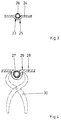
- FIG. 3 shows a recess 23 in a wall 24 of a fuel tank 25 biased line 26.
- the method in which the fuel tank 25 is generated is irrelevant here. Because of the tension in the recess 23, the line 26 is against a lateral Movement positively secured.
- Figure 4 shows a further embodiment of the form-fitting Securing a line 27 to a thermal deformable wall 28 of a fuel tank 29.
- the wall 28 in the area of the line 27 softened by heating and dash-dotted here pliers 30 shown from outside the fuel tank 29 deformed. After cooling it is Line 27 attached to the wall 28 in a form-fitting manner.
Landscapes
- Engineering & Computer Science (AREA)
- Mechanical Engineering (AREA)
- Life Sciences & Earth Sciences (AREA)
- Sustainable Development (AREA)
- Sustainable Energy (AREA)
- Chemical & Material Sciences (AREA)
- Combustion & Propulsion (AREA)
- Transportation (AREA)
- Cooling, Air Intake And Gas Exhaust, And Fuel Tank Arrangements In Propulsion Units (AREA)
Abstract
Description
- Fig.1a, 1b
- schematisch ein erfindungsgemäßes Verfahren zur Herstellung eines Kraftstoffbehälters im Blasverfahren,
- Fig.2a, 2b
- schematisch ein erfindungsgemäßes Verfahren zur Herstellung eines Kraftstoffbehälters aus zwei Formteilen,
- Fig.3
- eine formschlüssige Befestigung einer Leitung in einer Wandung eines Kraftstoffbehälters,
- Fig.4
- eine weitere Ausführungsform der formschlüssigen Befestigung einer Leitung in der Wandung des Kraftstoffbehälters.
Claims (13)
- Kraftstoffbehälter für ein Kraftfahrzeug mit mehreren zu seiner Belüftung oder zur Förderung von Kraftstoff vorgesehenen Leitungen, dadurch gekennzeichnet, daß die Leitungen (3 - 5, 16, 19, 26, 27) von zumindest einem Federelement (8, 9, 17, 18) gegen die Innenseite der Wandung (24, 27) des Kraftstoffbehälters (2, 15, 25, 29) vorgespannt sind.
- Kraftstoffbehälter nach Anspruch 1, dadurch gekennzeichnet, daß an den Leitungen (3 - 5, 16, 19) angeschlossene, im Innern des Kraftstoffbehälters (2, 15) angeordnete Bauteile (Saugstrahlpumpe 6, Schwalltopf 7, 20, 21) von dem Federelement (8, 9) gegen die Innenseite der Wandung des Kraftstoffbehälters (2, 15) vorgespannt sind.
- Kraftstoffbehälter nach Anspruch 1 oder 2, dadurch gekennzeichnet, daß die Leitungen (26, 27) formschlüssig an der Innenseite der Wandung (24, 28) befestigt sind.
- Kraftstoffbehälter nach zumindest einem der vorhergehenden Ansprüche, dadurch gekennzeichnet, daß die Wandung (24) des Kraftstoffbehälters (2, 25) Vertiefungen (12, 23) zur Aufnahme der Leitungen (26) oder der mit den Leitungen (4, 5) verbundenen Bauteile (Saugstrahlpumpe 6, Schwalltopf 7) hat.
- Kraftstoffbehälter nach zumindest einem der vorhergehenden Ansprüche, dadurch gekennzeichnet, daß das Federelement (8, 9, 17, 18) bügelförmig gestaltet ist.
- Kraftstoffbehälter nach zumindest einem der vorhergehenden Ansprüche, dadurch gekennzeichnet, daß mehrere der Leitungen (3 - 5) eine bauliche Einheit bilden.
- Kraftstoffbehälter nach zumindest einem der vorhergehenden Ansprüche, dadurch gekennzeichnet, daß die Leitungen (3 - 5, 16, 19, 26, 27) aus demselben Werkstoff gefertigt sind wie der Kraftstoffbehälter (2, 15, 25, 29).
- Kraftstoffbehälter nach zumindest einem der vorhergehenden Ansprüche, dadurch gekennzeichnet, daß das Federelement (8, 9, 17, 18) aus demselben Werkstoff gefertigt ist wie der Kraftstoffbehälter (2, 15).
- Kraftstoffbehälter nach zumindest einem der vorhergehenden Ansprüche, dadurch gekennzeichnet, daß das Federelement (8, 9, 17, 18) einteilig mit den Leitungen (3 - 5, 16, 19) gefertigt ist.
- Verfahren zur Montage von Leitungen in einem Kraftstoffbehälter, welcher durch ein Erwärmen mit anschließendem Aufblasen eines schlauchförmigen Rohlings innerhalb einer Form erzeugt wird, dadurch gekennzeichnet, daß die Leitungen an zumindest einem Federelement befestigt werden, das Federelement anschließend zusammengedrückt und zusammen mit den Leitungen in den Rohling eingeführt wird, und daß der Kraftstoffbehälter nach einem Entspannen des Federelementes durch das Erwärmen mit anschließendem Aufblasen erzeugt wird.
- Verfahren zur Montage von Leitungen in einem Kraftstoffbehälter, welcher durch Zusammenfügen zweier Formteile erzeugt wird, dadurch gekennzeichnet, daß die Leitungen an zumindest einem Federelement befestigt werden, daß ein Teil der Leitungen und/oder des Federelementes an der Innenseite einer der Formteile befestigt wird und daß die Formteile anschließend gegen die Kraft des Federelementes zusammengefügt werden.
- Verfahren nach Anspruch 10 oder 11, dadurch gekennzeichnet, daß die Leitungen und/oder das Federelement nach dem Zusammenfügen der Formteile oder dem Aufblasen des Kraftstoffbehälters an der Innenseite der Wandung des Kraftstoffbehälters verschweißt oder verklebt werden.
- Verfahren zur Montage von Leitungen in einem thermisch verformbaren Kraftstoffbehälter, nach zumindest einem der vorhergehenden Ansprüche, dadurch gekennzeichnet, daß nach dem Zusammenfügen der Formteile oder dem Aufblasen des Kraftstoffbehälters Bereiche der Wandung des Kraftstoffbehälters, gegen die die Leitungen vorgespannt sind, erwärmt und anschließend zur Erzeugung eines Formschlusses der Wandung mit den Leitungen plastisch verformt werden.
Applications Claiming Priority (2)
| Application Number | Priority Date | Filing Date | Title |
|---|---|---|---|
| DE19855387 | 1998-12-01 | ||
| DE19855387A DE19855387C2 (de) | 1998-12-01 | 1998-12-01 | Kraftstoffbehälter und Verfahren zur Montage von Leitungen in einem Kraftstoffbehälter |
Publications (3)
| Publication Number | Publication Date |
|---|---|
| EP1006014A2 true EP1006014A2 (de) | 2000-06-07 |
| EP1006014A3 EP1006014A3 (de) | 2002-01-23 |
| EP1006014B1 EP1006014B1 (de) | 2003-10-08 |
Family
ID=7889622
Family Applications (1)
| Application Number | Title | Priority Date | Filing Date |
|---|---|---|---|
| EP99123081A Expired - Lifetime EP1006014B1 (de) | 1998-12-01 | 1999-11-22 | Kraftstoffbehälter und Verfahren zur Montage von Leitungen in einem Kraftstoffbehälter |
Country Status (3)
| Country | Link |
|---|---|
| US (1) | US6138857A (de) |
| EP (1) | EP1006014B1 (de) |
| DE (2) | DE19855387C2 (de) |
Cited By (7)
| Publication number | Priority date | Publication date | Assignee | Title |
|---|---|---|---|---|
| WO2006095024A1 (en) * | 2005-03-11 | 2006-09-14 | Inergy Automotive Systems Research (Societe Anonyme) | Method for manufacturing a plastic fuel tank |
| WO2008003387A1 (de) * | 2006-07-07 | 2008-01-10 | Kautex Textron Gmbh & Co. Kg | Formwerkzeug zur herstellung von hohlkörpern aus thermoplastischem kunststoff mit einlegeteilen an der innenseite |
| WO2008061588A1 (en) * | 2006-11-21 | 2008-05-29 | Kautex Textron Gmbh & Co. Kg | Line arrangement in a plastic container |
| WO2008119576A1 (de) * | 2007-03-30 | 2008-10-09 | Robert Bosch Gmbh | Schwapptopf |
| FR2915923A1 (fr) * | 2007-05-10 | 2008-11-14 | Inergy Automotive Systems Res | Procede de fabrication d'un reservoir a carburant muni d'un accessoire interne |
| US7922949B2 (en) | 2006-07-07 | 2011-04-12 | Kautex Textron Gmbh & Co. Kg | Procedure for producing hollow bodies of thermoplastic material |
| US9346211B2 (en) | 2007-05-10 | 2016-05-24 | Plastic Omnium Advanced Innovation And Research | Process for manufacturing a fuel tank equipped with an internal accessory |
Families Citing this family (9)
| Publication number | Priority date | Publication date | Assignee | Title |
|---|---|---|---|---|
| DE10018310B4 (de) * | 2000-04-13 | 2005-07-14 | Daimlerchrysler Ag | Kraftstoffbehälter aus Kunststoff und Verfahren zu dessen Herstellung |
| WO2001083986A2 (en) | 2000-04-28 | 2001-11-08 | Alco Industries, Inc. D/B/A Schroeder Industries | Rotomolded hydraulic reservoir with integral extended length return line |
| US6298540B1 (en) * | 2000-09-28 | 2001-10-09 | Eaton Corporation | Combined fuel pump, level sender and rollover venting valve for a fuel tank |
| US20040144779A1 (en) * | 2003-01-24 | 2004-07-29 | Schulte Kale S. | Mounting clip for plastic containers |
| JP4108663B2 (ja) * | 2004-10-06 | 2008-06-25 | 本田技研工業株式会社 | 車両用燃料タンク |
| US20070235458A1 (en) * | 2006-04-10 | 2007-10-11 | Mann & Hummel Gmbh | Modular liquid reservoir |
| WO2012075355A1 (en) | 2010-12-03 | 2012-06-07 | Salflex Polymers Limited | Deployable fuel tank baffle and fuel tank system |
| US8491833B2 (en) * | 2011-06-17 | 2013-07-23 | Ti Automotive Technology Center Gmbh | Receptacle with integrally molded elongated elements |
| JP6923417B2 (ja) * | 2017-10-26 | 2021-08-18 | トヨタ自動車株式会社 | 燃料タンク |
Family Cites Families (12)
| Publication number | Priority date | Publication date | Assignee | Title |
|---|---|---|---|---|
| US1874008A (en) * | 1930-05-08 | 1932-08-30 | Henig Henry | Automatic spout |
| US2115016A (en) * | 1934-04-17 | 1938-04-26 | Atlantic Refining Co | Filling device |
| US2165357A (en) * | 1938-10-14 | 1939-07-11 | George W Emmert | Vent tube for fuel tanks |
| US2548734A (en) * | 1947-11-05 | 1951-04-10 | Scully Signal Co | Insertable vent pipe |
| DE2605321C3 (de) * | 1976-02-11 | 1979-06-21 | Messer Griesheim Gmbh, 6000 Frankfurt | Abgasleitung für stehende cryogene Behälter |
| FR2351029A1 (fr) * | 1976-05-11 | 1977-12-09 | Ouest Cie Produits Ind | Dispositif de remplissage et de degazage d'un reservoir de carburant, notamment pour vehicule automobile |
| US4224167A (en) * | 1979-03-19 | 1980-09-23 | Philip Buttigieg | Filler tube and filter attachment unit for fuel |
| DE3442149C2 (de) * | 1984-11-17 | 1987-04-23 | Adam Opel AG, 6090 Rüsselsheim | Vorrichtung zur Füllbegrenzung sowie zur Be- und Entlüftung von Kraftstoffbehältern von Kraftfahrzeugen |
| US5343902A (en) * | 1992-09-18 | 1994-09-06 | Solvay Automotive, Inc. | Internal gas removal system for fuel tank and method of making thereof |
| DE69315932T2 (de) * | 1992-09-18 | 1998-07-16 | Solvay Automotive Inc | System zur Abführung von Gasen für einen Kraftstofftank und Verfahren zu seiner Herstellung |
| DE29505421U1 (de) * | 1995-03-30 | 1996-08-01 | O & K Orenstein & Koppel Ag, 13581 Berlin | Behälter zur Aufnahme von Flüssigkeiten, wie Kraftstoffen, Hydraulikmedien o.dgl. |
| JP2986419B2 (ja) * | 1997-02-25 | 1999-12-06 | 本田技研工業株式会社 | 燃料注入装置 |
-
1998
- 1998-12-01 DE DE19855387A patent/DE19855387C2/de not_active Expired - Fee Related
-
1999
- 1999-11-22 EP EP99123081A patent/EP1006014B1/de not_active Expired - Lifetime
- 1999-11-22 DE DE59907277T patent/DE59907277D1/de not_active Expired - Fee Related
- 1999-11-30 US US09/450,627 patent/US6138857A/en not_active Expired - Fee Related
Non-Patent Citations (1)
| Title |
|---|
| None |
Cited By (14)
| Publication number | Priority date | Publication date | Assignee | Title |
|---|---|---|---|---|
| US8163228B2 (en) | 2005-03-11 | 2012-04-24 | Inergy Automotive Systems Research (Societe Anonyme) | Method for manufacturing a plastic fuel tank |
| WO2006095024A1 (en) * | 2005-03-11 | 2006-09-14 | Inergy Automotive Systems Research (Societe Anonyme) | Method for manufacturing a plastic fuel tank |
| US8329082B2 (en) | 2006-07-07 | 2012-12-11 | Kautex Textron Gmbh & Co. Kg | Procedure for producing hollow bodies of thermoplastic material |
| US7922949B2 (en) | 2006-07-07 | 2011-04-12 | Kautex Textron Gmbh & Co. Kg | Procedure for producing hollow bodies of thermoplastic material |
| WO2008003387A1 (de) * | 2006-07-07 | 2008-01-10 | Kautex Textron Gmbh & Co. Kg | Formwerkzeug zur herstellung von hohlkörpern aus thermoplastischem kunststoff mit einlegeteilen an der innenseite |
| WO2008061588A1 (en) * | 2006-11-21 | 2008-05-29 | Kautex Textron Gmbh & Co. Kg | Line arrangement in a plastic container |
| WO2008119576A1 (de) * | 2007-03-30 | 2008-10-09 | Robert Bosch Gmbh | Schwapptopf |
| US8960483B2 (en) | 2007-03-30 | 2015-02-24 | Robert Bosch Gmbh | Slosh pot |
| FR2915923A1 (fr) * | 2007-05-10 | 2008-11-14 | Inergy Automotive Systems Res | Procede de fabrication d'un reservoir a carburant muni d'un accessoire interne |
| WO2008138869A1 (en) * | 2007-05-10 | 2008-11-20 | Inergy Automotive Systems Research (Société Anonyme) | Process for manufacturing a fuel tank equipped with an internal accessory |
| US8282875B2 (en) | 2007-05-10 | 2012-10-09 | Inergy Automotive Systems Research (Societe Anonyme) | Process for manufacturing a fuel tank equipped with an internal accessory |
| US8636943B2 (en) | 2007-05-10 | 2014-01-28 | Inergy Automotive Systems Research (Societe Anonyme) | Process for manufacturing a fuel tank equipped with an internal accessory |
| EP2946907A1 (de) * | 2007-05-10 | 2015-11-25 | Plastic Omnium Advanced Innovation and Research | Verfahren zur herstellung eines mit internem zubehör ausgestatteten brennstofftanks |
| US9346211B2 (en) | 2007-05-10 | 2016-05-24 | Plastic Omnium Advanced Innovation And Research | Process for manufacturing a fuel tank equipped with an internal accessory |
Also Published As
| Publication number | Publication date |
|---|---|
| DE19855387C2 (de) | 2001-07-26 |
| US6138857A (en) | 2000-10-31 |
| DE59907277D1 (de) | 2003-11-13 |
| DE19855387A1 (de) | 2000-06-15 |
| EP1006014B1 (de) | 2003-10-08 |
| EP1006014A3 (de) | 2002-01-23 |
Similar Documents
| Publication | Publication Date | Title |
|---|---|---|
| EP1006014B1 (de) | Kraftstoffbehälter und Verfahren zur Montage von Leitungen in einem Kraftstoffbehälter | |
| DE60105948T2 (de) | Trägerstruktur für Kfz-Kühleranordnung | |
| DE19717473B4 (de) | Energieabsorberelement | |
| DE69908529T2 (de) | Verfahren zum Herstellen eines Tragwerks für die Frontseite von Kraftfahrzeugen ,und Tragwerk für die Frontseite von Kraftfahrzeugen hergestellt durch dieses Verfahren | |
| EP1675766B1 (de) | Verbundbauteil, insbesondere querträger | |
| DE102005041894B4 (de) | Trägerelement, insbesondere in einem Kraftfahrzeug | |
| EP0994768A1 (de) | Kunststoffbehälter und verfahren zu seiner herstellung | |
| EP0999082B1 (de) | Einfüllstutzen für einen Kraftstoffbehälter eines Kraftfahrzeuges | |
| DE102015207835A1 (de) | Kraftstoffbehälter für ein Kraftfahrzeug | |
| DE102012221555A1 (de) | Filteroberschale, Filter und Verfahren zum Herstellen einer Filteroberschale | |
| EP3445640B1 (de) | Strukturbauteil | |
| DE20003652U1 (de) | Strömungsleitvorrichtung zur Führung mindestens eines Gasstroms zur Füllung eines Gassacks und Airbagmodul | |
| EP1075395B1 (de) | Kraftstoffbehälter | |
| DE19902430C2 (de) | Verfahren zur Fertigung eines Behälters aus Kunststoff | |
| DE10147604A1 (de) | Dämpferlager zur Abstützung eines Stoßdämpfers an einem Fahrzeug | |
| EP2741905B1 (de) | Befestigung eines blasformbauteils | |
| DE19547177B4 (de) | Kraftstoffbehälter, der mit einem weiteren Behälter verbunden ist und Verfahren zu dessen Herstellung | |
| DE19732341B4 (de) | Stirnwand | |
| DE4424165A1 (de) | Kraftfahrzeug | |
| DE19602818A1 (de) | Flüssigkeitsbehälter aus Kunststoff | |
| DE102016220376A1 (de) | Radführungseinrichtung | |
| DE4426377A1 (de) | Befestigungsvorrichtung für einen Kühler | |
| DE69803318T2 (de) | Kapsel mit Dämpfervorrichtung zur Montage eines Spiegels in Automobilscheinwerfergehäuse | |
| DE4218797C1 (en) | Method to manufacture stiffener for hollow girder - uses cold extrusion process, and right angle bevelling on carrier ends | |
| EP0990547A2 (de) | Kunststoffbehälter |
Legal Events
| Date | Code | Title | Description |
|---|---|---|---|
| PUAI | Public reference made under article 153(3) epc to a published international application that has entered the european phase |
Free format text: ORIGINAL CODE: 0009012 |
|
| AK | Designated contracting states |
Kind code of ref document: A2 Designated state(s): AT BE CH CY DE DK ES FI FR GB GR IE IT LI LU MC NL PT SE Kind code of ref document: A2 Designated state(s): DE FR GB |
|
| AX | Request for extension of the european patent |
Free format text: AL;LT;LV;MK;RO;SI |
|
| PUAL | Search report despatched |
Free format text: ORIGINAL CODE: 0009013 |
|
| RAP1 | Party data changed (applicant data changed or rights of an application transferred) |
Owner name: SIEMENS AKTIENGESELLSCHAFT |
|
| AK | Designated contracting states |
Kind code of ref document: A3 Designated state(s): AT BE CH CY DE DK ES FI FR GB GR IE IT LI LU MC NL PT SE |
|
| AX | Request for extension of the european patent |
Free format text: AL;LT;LV;MK;RO;SI |
|
| 17P | Request for examination filed |
Effective date: 20020218 |
|
| AKX | Designation fees paid |
Free format text: DE FR GB |
|
| GRAH | Despatch of communication of intention to grant a patent |
Free format text: ORIGINAL CODE: EPIDOS IGRA |
|
| GRAS | Grant fee paid |
Free format text: ORIGINAL CODE: EPIDOSNIGR3 |
|
| GRAA | (expected) grant |
Free format text: ORIGINAL CODE: 0009210 |
|
| AK | Designated contracting states |
Kind code of ref document: B1 Designated state(s): DE FR GB |
|
| REG | Reference to a national code |
Ref country code: GB Ref legal event code: FG4D Free format text: NOT ENGLISH |
|
| REG | Reference to a national code |
Ref country code: IE Ref legal event code: FG4D Free format text: GERMAN |
|
| REF | Corresponds to: |
Ref document number: 59907277 Country of ref document: DE Date of ref document: 20031113 Kind code of ref document: P |
|
| GBT | Gb: translation of ep patent filed (gb section 77(6)(a)/1977) |
Effective date: 20040106 |
|
| REG | Reference to a national code |
Ref country code: IE Ref legal event code: FD4D |
|
| ET | Fr: translation filed | ||
| PLBE | No opposition filed within time limit |
Free format text: ORIGINAL CODE: 0009261 |
|
| STAA | Information on the status of an ep patent application or granted ep patent |
Free format text: STATUS: NO OPPOSITION FILED WITHIN TIME LIMIT |
|
| 26N | No opposition filed |
Effective date: 20040709 |
|
| PGFP | Annual fee paid to national office [announced via postgrant information from national office to epo] |
Ref country code: GB Payment date: 20051108 Year of fee payment: 7 |
|
| PGFP | Annual fee paid to national office [announced via postgrant information from national office to epo] |
Ref country code: FR Payment date: 20051122 Year of fee payment: 7 |
|
| PGFP | Annual fee paid to national office [announced via postgrant information from national office to epo] |
Ref country code: DE Payment date: 20060123 Year of fee payment: 7 |
|
| PG25 | Lapsed in a contracting state [announced via postgrant information from national office to epo] |
Ref country code: DE Free format text: LAPSE BECAUSE OF NON-PAYMENT OF DUE FEES Effective date: 20070601 |
|
| GBPC | Gb: european patent ceased through non-payment of renewal fee |
Effective date: 20061122 |
|
| REG | Reference to a national code |
Ref country code: FR Ref legal event code: ST Effective date: 20070731 |
|
| PG25 | Lapsed in a contracting state [announced via postgrant information from national office to epo] |
Ref country code: GB Free format text: LAPSE BECAUSE OF NON-PAYMENT OF DUE FEES Effective date: 20061122 |
|
| PG25 | Lapsed in a contracting state [announced via postgrant information from national office to epo] |
Ref country code: FR Free format text: LAPSE BECAUSE OF NON-PAYMENT OF DUE FEES Effective date: 20061130 |