EP1005634B1 - Near normal incidence optical assaying method having wavelength and angle sensitivity - Google Patents
Near normal incidence optical assaying method having wavelength and angle sensitivity Download PDFInfo
- Publication number
- EP1005634B1 EP1005634B1 EP98942094A EP98942094A EP1005634B1 EP 1005634 B1 EP1005634 B1 EP 1005634B1 EP 98942094 A EP98942094 A EP 98942094A EP 98942094 A EP98942094 A EP 98942094A EP 1005634 B1 EP1005634 B1 EP 1005634B1
- Authority
- EP
- European Patent Office
- Prior art keywords
- sensor
- angle
- anomaly
- angles
- incident angles
- Prior art date
- Legal status (The legal status is an assumption and is not a legal conclusion. Google has not performed a legal analysis and makes no representation as to the accuracy of the status listed.)
- Expired - Lifetime
Links
- 238000000034 method Methods 0.000 title claims description 16
- 230000003287 optical effect Effects 0.000 title claims description 11
- 230000035945 sensitivity Effects 0.000 title description 7
- 239000000126 substance Substances 0.000 claims description 48
- 238000000926 separation method Methods 0.000 claims description 20
- 238000002198 surface plasmon resonance spectroscopy Methods 0.000 description 29
- 229910052751 metal Inorganic materials 0.000 description 16
- 239000002184 metal Substances 0.000 description 16
- 230000001235 sensitizing effect Effects 0.000 description 12
- 239000000758 substrate Substances 0.000 description 9
- 230000010287 polarization Effects 0.000 description 8
- 238000002310 reflectometry Methods 0.000 description 8
- 230000000694 effects Effects 0.000 description 6
- 230000003993 interaction Effects 0.000 description 5
- 239000000463 material Substances 0.000 description 5
- 239000010409 thin film Substances 0.000 description 5
- 238000003491 array Methods 0.000 description 4
- 238000001514 detection method Methods 0.000 description 4
- 238000005259 measurement Methods 0.000 description 4
- 229910052709 silver Inorganic materials 0.000 description 4
- 239000004332 silver Substances 0.000 description 4
- 239000000427 antigen Substances 0.000 description 3
- 102000036639 antigens Human genes 0.000 description 3
- 108091007433 antigens Proteins 0.000 description 3
- 239000011521 glass Substances 0.000 description 3
- 239000004065 semiconductor Substances 0.000 description 3
- 229910052581 Si3N4 Inorganic materials 0.000 description 2
- VYPSYNLAJGMNEJ-UHFFFAOYSA-N Silicium dioxide Chemical compound O=[Si]=O VYPSYNLAJGMNEJ-UHFFFAOYSA-N 0.000 description 2
- BQCADISMDOOEFD-UHFFFAOYSA-N Silver Chemical compound [Ag] BQCADISMDOOEFD-UHFFFAOYSA-N 0.000 description 2
- 229910052782 aluminium Inorganic materials 0.000 description 2
- XAGFODPZIPBFFR-UHFFFAOYSA-N aluminium Chemical compound [Al] XAGFODPZIPBFFR-UHFFFAOYSA-N 0.000 description 2
- 230000003321 amplification Effects 0.000 description 2
- 238000013459 approach Methods 0.000 description 2
- 230000000295 complement effect Effects 0.000 description 2
- 230000001419 dependent effect Effects 0.000 description 2
- 230000005284 excitation Effects 0.000 description 2
- 239000010408 film Substances 0.000 description 2
- PCHJSUWPFVWCPO-UHFFFAOYSA-N gold Chemical compound [Au] PCHJSUWPFVWCPO-UHFFFAOYSA-N 0.000 description 2
- 229910052737 gold Inorganic materials 0.000 description 2
- 239000010931 gold Substances 0.000 description 2
- 238000003199 nucleic acid amplification method Methods 0.000 description 2
- 230000000737 periodic effect Effects 0.000 description 2
- VZGDMQKNWNREIO-UHFFFAOYSA-N tetrachloromethane Chemical compound ClC(Cl)(Cl)Cl VZGDMQKNWNREIO-UHFFFAOYSA-N 0.000 description 2
- 238000012546 transfer Methods 0.000 description 2
- 108091032973 (ribonucleotides)n+m Proteins 0.000 description 1
- 102100023635 Alpha-fetoprotein Human genes 0.000 description 1
- 108090001008 Avidin Proteins 0.000 description 1
- 241000283690 Bos taurus Species 0.000 description 1
- 108091003079 Bovine Serum Albumin Proteins 0.000 description 1
- 108010038061 Chymotrypsinogen Proteins 0.000 description 1
- 108020004414 DNA Proteins 0.000 description 1
- WQZGKKKJIJFFOK-GASJEMHNSA-N Glucose Natural products OC[C@H]1OC(O)[C@H](O)[C@@H](O)[C@@H]1O WQZGKKKJIJFFOK-GASJEMHNSA-N 0.000 description 1
- 101000766306 Homo sapiens Serotransferrin Proteins 0.000 description 1
- 108091006905 Human Serum Albumin Proteins 0.000 description 1
- 102000008100 Human Serum Albumin Human genes 0.000 description 1
- 102000004856 Lectins Human genes 0.000 description 1
- 108090001090 Lectins Proteins 0.000 description 1
- XSQUKJJJFZCRTK-UHFFFAOYSA-N Urea Chemical compound NC(N)=O XSQUKJJJFZCRTK-UHFFFAOYSA-N 0.000 description 1
- 108010026331 alpha-Fetoproteins Proteins 0.000 description 1
- WQZGKKKJIJFFOK-VFUOTHLCSA-N beta-D-glucose Chemical compound OC[C@H]1O[C@@H](O)[C@H](O)[C@@H](O)[C@@H]1O WQZGKKKJIJFFOK-VFUOTHLCSA-N 0.000 description 1
- 239000012620 biological material Substances 0.000 description 1
- 230000005540 biological transmission Effects 0.000 description 1
- 239000004202 carbamide Substances 0.000 description 1
- 230000015556 catabolic process Effects 0.000 description 1
- 230000007812 deficiency Effects 0.000 description 1
- 238000006731 degradation reaction Methods 0.000 description 1
- 239000003989 dielectric material Substances 0.000 description 1
- -1 dinitrophenyl Chemical group 0.000 description 1
- 239000007789 gas Substances 0.000 description 1
- 239000000499 gel Substances 0.000 description 1
- 239000008103 glucose Substances 0.000 description 1
- BCQZXOMGPXTTIC-UHFFFAOYSA-N halothane Chemical compound FC(F)(F)C(Cl)Br BCQZXOMGPXTTIC-UHFFFAOYSA-N 0.000 description 1
- 229960003132 halothane Drugs 0.000 description 1
- 239000000017 hydrogel Substances 0.000 description 1
- 238000012804 iterative process Methods 0.000 description 1
- 108010045069 keyhole-limpet hemocyanin Proteins 0.000 description 1
- 239000002523 lectin Substances 0.000 description 1
- 239000011159 matrix material Substances 0.000 description 1
- 238000013208 measuring procedure Methods 0.000 description 1
- 238000012544 monitoring process Methods 0.000 description 1
- 230000003647 oxidation Effects 0.000 description 1
- 238000007254 oxidation reaction Methods 0.000 description 1
- 229920000323 polyazulene Polymers 0.000 description 1
- 230000001681 protective effect Effects 0.000 description 1
- XNSAINXGIQZQOO-SRVKXCTJSA-N protirelin Chemical compound NC(=O)[C@@H]1CCCN1C(=O)[C@@H](NC(=O)[C@H]1NC(=O)CC1)CC1=CN=CN1 XNSAINXGIQZQOO-SRVKXCTJSA-N 0.000 description 1
- 239000000377 silicon dioxide Substances 0.000 description 1
- HQVNEWCFYHHQES-UHFFFAOYSA-N silicon nitride Chemical compound N12[Si]34N5[Si]62N3[Si]51N64 HQVNEWCFYHHQES-UHFFFAOYSA-N 0.000 description 1
- 241000894007 species Species 0.000 description 1
- 238000004528 spin coating Methods 0.000 description 1
- XLYOFNOQVPJJNP-UHFFFAOYSA-N water Substances O XLYOFNOQVPJJNP-UHFFFAOYSA-N 0.000 description 1
Images




Classifications
-
- G—PHYSICS
- G01—MEASURING; TESTING
- G01N—INVESTIGATING OR ANALYSING MATERIALS BY DETERMINING THEIR CHEMICAL OR PHYSICAL PROPERTIES
- G01N21/00—Investigating or analysing materials by the use of optical means, i.e. using sub-millimetre waves, infrared, visible or ultraviolet light
- G01N21/75—Systems in which material is subjected to a chemical reaction, the progress or the result of the reaction being investigated
- G01N21/77—Systems in which material is subjected to a chemical reaction, the progress or the result of the reaction being investigated by observing the effect on a chemical indicator
- G01N21/7703—Systems in which material is subjected to a chemical reaction, the progress or the result of the reaction being investigated by observing the effect on a chemical indicator using reagent-clad optical fibres or optical waveguides
- G01N21/774—Systems in which material is subjected to a chemical reaction, the progress or the result of the reaction being investigated by observing the effect on a chemical indicator using reagent-clad optical fibres or optical waveguides the reagent being on a grating or periodic structure
- G01N21/7743—Systems in which material is subjected to a chemical reaction, the progress or the result of the reaction being investigated by observing the effect on a chemical indicator using reagent-clad optical fibres or optical waveguides the reagent being on a grating or periodic structure the reagent-coated grating coupling light in or out of the waveguide
-
- G—PHYSICS
- G01—MEASURING; TESTING
- G01N—INVESTIGATING OR ANALYSING MATERIALS BY DETERMINING THEIR CHEMICAL OR PHYSICAL PROPERTIES
- G01N21/00—Investigating or analysing materials by the use of optical means, i.e. using sub-millimetre waves, infrared, visible or ultraviolet light
- G01N21/17—Systems in which incident light is modified in accordance with the properties of the material investigated
- G01N21/55—Specular reflectivity
- G01N21/552—Attenuated total reflection
- G01N21/553—Attenuated total reflection and using surface plasmons
-
- G—PHYSICS
- G01—MEASURING; TESTING
- G01N—INVESTIGATING OR ANALYSING MATERIALS BY DETERMINING THEIR CHEMICAL OR PHYSICAL PROPERTIES
- G01N21/00—Investigating or analysing materials by the use of optical means, i.e. using sub-millimetre waves, infrared, visible or ultraviolet light
- G01N21/17—Systems in which incident light is modified in accordance with the properties of the material investigated
- G01N21/55—Specular reflectivity
- G01N21/552—Attenuated total reflection
- G01N21/553—Attenuated total reflection and using surface plasmons
- G01N21/554—Attenuated total reflection and using surface plasmons detecting the surface plasmon resonance of nanostructured metals, e.g. localised surface plasmon resonance
-
- Y—GENERAL TAGGING OF NEW TECHNOLOGICAL DEVELOPMENTS; GENERAL TAGGING OF CROSS-SECTIONAL TECHNOLOGIES SPANNING OVER SEVERAL SECTIONS OF THE IPC; TECHNICAL SUBJECTS COVERED BY FORMER USPC CROSS-REFERENCE ART COLLECTIONS [XRACs] AND DIGESTS
- Y10—TECHNICAL SUBJECTS COVERED BY FORMER USPC
- Y10S—TECHNICAL SUBJECTS COVERED BY FORMER USPC CROSS-REFERENCE ART COLLECTIONS [XRACs] AND DIGESTS
- Y10S436/00—Chemistry: analytical and immunological testing
- Y10S436/805—Optical property
-
- Y—GENERAL TAGGING OF NEW TECHNOLOGICAL DEVELOPMENTS; GENERAL TAGGING OF CROSS-SECTIONAL TECHNOLOGIES SPANNING OVER SEVERAL SECTIONS OF THE IPC; TECHNICAL SUBJECTS COVERED BY FORMER USPC CROSS-REFERENCE ART COLLECTIONS [XRACs] AND DIGESTS
- Y10—TECHNICAL SUBJECTS COVERED BY FORMER USPC
- Y10S—TECHNICAL SUBJECTS COVERED BY FORMER USPC CROSS-REFERENCE ART COLLECTIONS [XRACs] AND DIGESTS
- Y10S436/00—Chemistry: analytical and immunological testing
- Y10S436/806—Electrical property or magnetic property
-
- Y—GENERAL TAGGING OF NEW TECHNOLOGICAL DEVELOPMENTS; GENERAL TAGGING OF CROSS-SECTIONAL TECHNOLOGIES SPANNING OVER SEVERAL SECTIONS OF THE IPC; TECHNICAL SUBJECTS COVERED BY FORMER USPC CROSS-REFERENCE ART COLLECTIONS [XRACs] AND DIGESTS
- Y10—TECHNICAL SUBJECTS COVERED BY FORMER USPC
- Y10S—TECHNICAL SUBJECTS COVERED BY FORMER USPC CROSS-REFERENCE ART COLLECTIONS [XRACs] AND DIGESTS
- Y10S436/00—Chemistry: analytical and immunological testing
- Y10S436/807—Apparatus included in process claim, e.g. physical support structures
Definitions
- This invention relates generally to the field of optical sensing and, more particularly, to a method and apparatus for assaying chemical and biological materials.
- SPR surface plasmon resonance
- These sensors are capable of detecting the presence of a wide variety of materials in concentrations as low as picomoles per liter.
- SPR sensors have been constructed to detect many biomolecules including dinitrophenyl, keyhole limpet hemocyanin, ⁇ -Feto protein, IgE, IgG, bovine and human serum albumin, glucose, urea, avidin, lectin, DNA, RNA, hapten, HIV antibodies, human transferrin, and chymotrypsinogen.
- SPR sensors have been built which detect chemicals such as polyazulene and various gases including halothane, tricloroethane and carbon tetrachloride.
- An SPR sensor is constructed by sensitizing a surface of a substrate to a specific substance.
- the surface of the substrate is coated with a thin film of metal such as silver, gold or aluminum.
- a monomolecular layer of receptive material such as complementary antigens, is covalently bonded to the surface of the thin film.
- the thin film is capable of interacting with a predetermined chemical, biochemical or biological substance.
- the most common SPR sensor involves exposing the surface of the sensor to a light beam through a glass prism.
- a specific angle of incidence known as the resonance angle
- a component of the light beam's wavevector in the plane of the sensor surface matches a wavevector of a surface plasmon in the thin film, resulting in very efficient energy transfer and excitation of the surface plasmon in the thin film.
- the resonance angle the amount of reflected light from the surface of the sensor changes.
- a sharp attenuation or amplification is exhibited and the resonance angle of a SPR sensor can be readily detected.
- SPR sensors have also been constructed using metallized diffraction gratings instead of prisms.
- resonance occurs when a component of the incident light polarization is perpendicular to the groove direction of the grating and the angle of incidence is appropriate for energy transfer .and excitation of the thin metal film.
- prism-based sensors a change in the amount of light reflected is observed when the angle of incidence equals the resonance angle.
- Previous SPR grating sensors have incorporated square-wave or sinusoidal groove profiles.
- EP-A-0 305 109 describes a sensor for use in a SPR method for assaying a substance in a sample by means of exposing it to light spanning over a plurality of angles whereafter the light is reflected from the sample and then detected over a second span of angles.
- the invention is a method for assaying a substance in a sample using a surface plasmon resonance sensor having a diffraction grating surface as defined in claim 1.
- the incident angles may include a first plurality of incident angles and a second plurality of incident angles, wherein the first plurality of incident angles are positive in angle from a normal to the surface of the sensor and the second plurality of incident angles are negative in angle from the normal.
- the step of detecting the anomaly angles of the first exposure step may include the steps of: (i) detecting light reflected from the sensor during the first exposing step for each angle of the first plurality of incident angles and for each angle of the second plurality of incident angles, and (ii) determining a first anomaly angle and a second anomaly angle, wherein the first anomaly angle is an angle of the first plurality of incident angles at which a change in reflected light is detected during the first exposing step and wherein the second anomaly angle is an angle of the second plurality of incident angles at which a change in reflected light is detected during the first exposing step.
- the step of detecting the anomaly angles of the second exposure step may include the steps of: (i) detecting light reflected from the sensor during the second exposing step for each angle of the first plurality of incident angles and for each angle of the second plurality of incident angles, (ii) determining a third anomaly angle and a fourth anomaly angle, wherein the third anomaly angle is an angle of the first plurality of incident angles at which a change in reflected light is detected during the second exposing step and wherein the fourth anomaly angle is an angle of the second plurality of incident angles at which a change in reflected light is detected during the second exposing step.
- the light source may be a wavelength-tunable laser source and the determining step includes the steps of: adjusting the wavelength of the light beam by tuning the laser source such that an angular separation between the third anomaly angle and the fourth anomaly angle substantially equals an angular separation between the first anomaly angle and the second anomaly angle, and calculating a measure of the substance in the sample as a function of the tuned wavelength.
- FIG. 1 illustrates a sensing system 10 for use with the method according to the present invention.
- sensing system 10 includes light source 20, beamsplitter 30, lens 40, optical sensor 50 and detector array 60.
- sensor 50 is a surface plasmon resonance (SPR) diffraction grating sensor having a metallized diffraction grating.
- SPR surface plasmon resonance
- sensor 50 is a diffraction anomaly sensor discussed in detail below.
- Light source 20 produces a first light beam 25 which is directed to beamsplitter 30.
- light source 20 is a laser source capable of emitting a laser beam.
- Beamsplitter 30 divides first light beam 25 into second light beam 32 and third light beam 34.
- Lens 40 focuses second light beam 32 onto sensor 50 over a range of angles of incidence while third light beam 34 is unused by sensing system 10.
- beamsplitter 30 and lens 40 are not critical to the invention but allow sensing system 10 to be constructed in a compact manner without requiring moving parts.
- sensor 50 is rotated along an axis normal to second light beam 32 thereby changing the angle of incidence and eliminating the need for lens 40.
- light source 20 is rotated thereby changing the angle of incidence of second light beam 32 on sensor 50.
- Sensor 50 may be designed, as detailed below, such that exposure via second light beam 32 over a range of near-normal angles results in a diffraction anomaly at both small positive and negative angles of incidence.
- the zero order reflectance of sensor 50 changes.
- sensor 50 may be designed to work over a greater range of positive and negative angles
- light beam 32 is directed upon sensor 50 at angles ranging up to ⁇ 20° from the normal. It is preferred, however, that light beam 32 is directed over a smaller range of angles such as up to ⁇ 10° from the normal.
- the positive and negative angles of incidence at which the anomaly occurs are indicated in Figure 1 by ⁇ 1 and ⁇ 2 and will be referred to as the positive and negative anomaly angles.
- the substance When sensor 50 is exposed to a sample containing a targeted substance, the substance attaches to a surface of sensor 50 and changes the effective index of refraction at the surface of sensor 50. This corresponding change in the index of refraction shifts both anomaly angles ⁇ 1 and ⁇ 2 .
- the angular separation between the positive and negative anomaly angles is strongly dependent upon the amount of targeted substance present in the sample.
- a quantitative measure of the targeted substance can be calculated by measuring the angular separation between the anomaly angles. More specifically, after exposing sensor 50 to the sample, new anomaly angles ⁇ 1 and ⁇ 2 are determined by directing second light beam 32 to sensor 50 over a range of near-normal incidence angles.
- Lens 40 collects diffracted light from sensor 50 and collimates it into light beam 70 which is incident upon polarizing beamsplitter 80.
- Polarizing beamsplitter 80 splits light beam 70 into component 85, having a polarization vector parallel to the grooves of the surface of sensor 50, and component 90, having a polarization vector perpendicular to the grooves of the surface of sensor 50.
- Components 85 and 90 are incident upon detector array 60 and detector array 65, respectively.
- Detector arrays 60 and 65 each include a plurality of sensing elements.
- a controller (not shown) monitors the sensing elements of detector arrays 60 and 65 and continuously ratios the intensities of light component 85 and light component 90 for corresponding sensing elements of detector arrays 60 and 65. In this manner, light fluctuations of the light source, or other system variations such as ripples in the sample, do not affect the calculation of the targeted species in the sample.
- the controller determines the current anomaly angles ⁇ 1 and ⁇ 2 and calculates a measure of the targeted substance in the sample based on the angular separation between the anomaly angles. In another embodiment, the controller monitors anomaly angles ⁇ 1 and ⁇ 2 and sounds an alarm when the measure of the targeted substance exceed a predetermined threshold.
- sensor 50 may be disposed or may be washed and reused.
- sensing system 10 and sensor 50 are effectively twice that of conventional SPR sensors.
- Conventional SPR sensors measure a shift in a single resonance angle.
- Sensing system 10 by measuring the angular separation between two anomaly angles, is capable of greater precision.
- sensing system 10 is less susceptible to system drifts due to mechanical motion and thermal changes than conventional SPR sensors. Since conventional systems depend upon precise measurement of an absolute angle, any mechanical drift in the angle of incidence can result in faulty readings. By measuring the separation between anomaly angles, sensing system 10 does not depend on an absolute measurement but a "relative" measurement of anomaly angles ⁇ 1 and ⁇ 2 . Therefore, the effect of mechanical drifts are substantially neutralized.
- sensing system 10 is the need for only a single window (not shown) for receiving second light beam 32 from light source 20 and for allowing diffracted light 70 to escape to lens 40 and ultimately to detector array 60.
- Conventional SPR grating sensors are designed for a large angle of incidence, such as 45°, thereby requiring multiple windows for light passage.
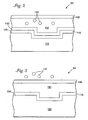
- sensor 50 is a SPR diffraction grating sensor suitable for use with the present invention as illustrated in Figure 2.
- Sensor 50 includes substrate 100 having a surface 105 formed in a groove profile.
- surface 105 is illustrated as a substantially periodic square profile. Other surface profiles are contemplated including sinusoidal, trapezoidal and triangular.
- the period of surface 105 may range from less than 0.4 micrometers to over 2.0 micrometers. As discussed in detail below, by adjusting the period of the groove profile of surface 105, it is possible to excite the surface plasmon with light at near normal incidence, thereby causing a diffraction anomaly.
- Thin metal layer 110 is formed outwardly from surface 105 of substrate 100 and comprises any suitable metal such as aluminum, gold or silver. In one embodiment, layer 110 comprises silver having a thickness of approximately 100 nm. Sensitizing layer 130 is formed outwardly from layer 110. Sensitizing layer 130 is selected to interact with a predetermined chemical, biochemical or biological substance 140 contained in sample 150. In one embodiment, sensitizing layer 130 comprises a layer of antigens capable of trapping a complementary antibody. Recently, several techniques have been developed for attaching antigens as a receptive material to layer 110 such as spin coating with a porous silica sol-gel or a hydrogel matrix. Preferably, sensitizing layer 130 is less than 100 nm thick.
- Glass window 135 allows second light beam 32 to enter sensor 50 and diffracted light 70 to escape sensor 50 to lens 40 and ultimately to detector array 60. Any refraction effects caused by window 135 on second light beam 32 are minimized because second light beam 32 is substantially normal to window 135 at the air-glass interface. Additionally, it is preferable that window 135 is coated with an anti-reflection material, in order to further reduce optical effects.
- ⁇ sp is the azimuthal angle of second light beam 32 with respect to the grooves of surface 105
- n o is the index of refraction of sample 150
- n m + iK m is the index of refraction for metal layer 110
- ⁇ is the wavelength of second light beam 32
- p is the period of the grooves of surface 105
- m is an integer.
- n o is the index of refraction of sample 150
- n m + iK m is the index of refraction for metal layer 110
- ⁇ is the wavelength of second light beam 32
- P is the period of the grooves of surface 105 of substrate 100
- m is an integer.
- sensor 50 is a diffraction anomaly sensor as illustrated in Figure 3.
- Sensor 50 includes substrate 160, having a surface 165, and thin metal layer 170 which are substantially the same as in SPR grating sensor of Figure 2.
- Dielectric layer 180 is formed outwardly from metal layer 170 and thereby protects metal layer 170 from oxidation and general degradation.
- metal layer 170 may comprise any suitable metal and may be selected to optimize sensitivity.
- metal layer 170 comprises silver having a thickness of approximately 100 nm.
- the diffraction anomaly exhibited by sensor 50 is directly affected by thickness of dielectric layer 180. It is preferable that the dielectric layer 180 has a thickness of at least 50 nm or, more preferably, at least 130.nm.
- sensitizing layer 190 is formed outwardly from dielectric layer 180 as shown in Figure 3. Sensitizing layer 190 is selected to interact with a predetermined chemical, biochemical or biological substance 140 contained in the sample. In another embodiment, dielectric layer 180 is selected so as to interact directly with substance 140, thereby eliminating the need for sensitizing layer 190.
- diffraction anomaly sensor 50 exhibits a change in reflectivity for light polarized parallel to the grooves of surface 165:
- light beam 25 has an angle of incidence equal to the diffraction anomaly angle for sensor 50, diffracted light beam 70 is not received by detector array 60 but propagates within dielectric layer 180.
- dielectric layer 180 acts as a waveguide and a change in reflectivity is readily detected by the controller.
- ⁇ SP diffraction anomaly angle
- ⁇ 0 is the dielectric constant of the medium above the substrate, such as air or water, etc.
- ⁇ 1 is the dielectric constant of the dielectric layer
- ⁇ 2 is the dielectric constant of the metal film.
- k 0 is a wavevector of the incident light in vacuum and equals 2 ⁇ / ⁇ .
- d is the thickness of the dielectric layer.
- ⁇ sp is the azimuthal angle of second light beam 32 with respect to the grooves of surface 165, where 0° corresponds to the plane of incidence perpendicular to the groove direction, n o is the index of refraction of the sample, ⁇ is the wavelength of second light beam 32, p is the period of the grooves of surface 165, and m is an integer.
- a dielectric layer having a suitable dielectric constant may be readily selected so as to suppress light beam component 85 which has a polarization parallel to the grooves in surface 165 of sensor 50.
- Figure 4 plots the calculated reflectance of sensor 50 over a range of incidence angles for second light beam 32. More specifically, the reflectance of sensor 50 is plotted for incidence angles ranging from 0° (normal) to 2° and an azimuthal angle of 0°. Furthermore, reflectivity is plotted for various refractive indices (n) of sensitizing layer 130 of sensor 50 and for various wavelengths ( ⁇ ) of second light beam 32. It is evident from Figure 4 that at a fixed wavelength of 782.5 nm, an increase in the index of refraction of sensitizing layer 130 of sensor 50 from 1.4 to 1.59 and results in a shift of the anomaly angle by approximately 0.25 degrees.
- diffraction grating sensors are highly dispersive in wavelength in addition to angle of incidence.
- the embodiments described above measure the concentration of a targeted substance by observing a shift in anomaly angle for incident light having a fixed wavelength.
- the concentration of a targeted substance can also be measured by observing the reflectivity of an optical sensor over a range of wavelengths of an incident light beam having a fixed angle of incidence.
- a substance may be detected by using a wavelength-tunable laser, thereby eliminating the need for moving parts to modify the angle of incidence.
- Figure 5 plots the reflectance of a diffraction grating sensor over a range of wavelengths for an incident light beam having a fixed angle of incidence. More specifically, Figure 5 plots reflectance versus wavelength over a range of wavelengths from 760 nm to 810 nm. Furthermore, reflectivity is plotted for various refractive indices (n). Referring to Figure 5, at a near normal angle of incidence, a first anomaly in reflected light occurs at wavelength R1 and a second anomaly occurs at wavelength R2.
- An increase in the index of refraction from 1.4 to 1.5 of sensitizing layer 130 changes the wavelengths at which the first and second anomaly occur from R1 and R2 to R1' and R2', respectively.
- the separation in wavelength between the first and second anomalies remains fixed.
- a quantitative measure of the targeted substance can be calculated by measuring the shift between anomaly wavelengths. As can be seen in Figure 5, when the refractive index increases from 1.4 to 1.59, the anomaly wavelength shifts from R1 to R1', a change of approximately 5 nm which is readily detectable.
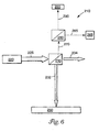
- FIG. 6 illustrates a sensing system 21D capable of sensing an absorbed substance by detecting a shift in anomaly wavelength in accordance with the present invention.
- sensing system 210 includes light source 220, beamsplitter 230, diffraction grating sensor 250 and detector 260.
- Light source 220 produces light beam 225 which is directed via beamsplitter 230 toward sensor 250 at a near normal incidence angle.
- Beamsplitter 230 is not essential but is illustrated because it allows for sensing system 210 to be implemented in a more compact manner.
- light source 220 is a wavelength tunable laser source thereby facilitating detection of wavelengths at which a diffraction anomaly occurs.
- Sensor 250 diffracts light beam 232 thereby producing diffracted light beam 270 incident upon polarizing beamsplitter 280.
- Polarizing beamsplitter 280 splits light beam 270 into component 285, having a polarisation vector parallel to the grooves of the surface of sensor 250, and component 290, having a polarization vector perpendicular to the grooves of the surface of sensor 250.
- Components 285 and 290 are incident upon detector 265 and detector 260, respectively.
- Detectors 260 and 265 each produce an output signal proportional to the amount of light received.
- a change in reflectivity occurs such as a very sharp attenuation or amplification in reflectivity of component 290 is observed by detector 260.
- a controller determines the current anomaly wavelengths by controlling light source 220 to emit light over a desired range of wavelengths and monitoring the corresponding output signals from detectors 260 and 265. The controller ratios the output signals from detectors 260 and 265, determines the new anomaly wavelengths corresponding to a change in reflectivity from sensor 250 and calculates the amount of targeted substance present in the sample based on the magnitude of the shift in anomaly wavelengths.
- light source 20 of sensing system 10 is a wavelength tunable semiconductor laser source thereby facilitating detection of anomaly wavelengths.
- the controller (not shown) directs second light beam 32 to sensor 50 over a range of near-normal incidence angles and determines the current angles of attenuation ⁇ 1 and ⁇ 2 .
- the controller tunes the wavelength of second light beam 32 by tuning light source 20 such that the angular separation between anomaly angles ⁇ 1 and ⁇ 2 is unchanged.
- the controller calculates the concentration of the substance in the sample as a function of the tuned wavelength.
- measurement of the shift between anomaly wavelengths can also be used to insure there has been no change in the angle of incidence, or to correct for such a change in the event that a change has occurred. In this manner, the sensitivity and precision of the sensing system can be maximized.
- sensing system 310 includes light source 320, first optical sensor 350, second optical sensor 355 and detector 360.
- Light source 320 produces light beam 325 incident on first sensor 350.
- light source 320 is a wavelength tunable semiconductor laser source thereby facilitating detection of anomaly wavelengths.
- Light beam 325 is reflected by first sensor 350 to second sensor 355, located proximate to sensor 350, and ultimately to polarizing beamsplitter 370.
- Polarizing beamsplitter 370 splits light beam 310 into component 385, having a polarization vector parallel to the grooves of the surface of sensor 350, and component 390, having a polarization vector perpendicular to the grooves of the surface of sensor 350.
- Components 385 and 390 are incident upon detector 365 and detector 360, respectively.
- Detectors 360 and 365 each produce an output signal proportional to the amount of light received.
- First sensor 350 is similar to sensor 50 illustrated in Figure 2 and described above.
- Second sensor 355, however, is insensitized to interaction with the sample.
- sensor 355 comprises substrate 400, having a surface 405 formed in a periodic trapezoidal groove profile, and thin metal layer 410 formed outwardly from surface 405.
- Sensor 350 further comprises dielectric layer 420 formed outward from layer 410, thereby insulating sensor 350 from interaction with the sample.
- Dielectric layer 420 comprises any suitable dielectric material such as silicon nitride, Si 3 N 4 , and is preferably at least 150 nm thick.
- sensor 355 comprises substrate 400 and thin metal layer 410 and does not include a sensitizing layer or a dielectric layer. In this configuration, sensor 355 does not interact with the sample. This embodiment, however, has the disadvantage that metal layer 410 is exposed to the sample and may degrade.
- sensor 350 and sensor 355 form a double anomaly grating.
- the corresponding anomaly angles of sensor 350 and sensor 355 are affected by drifts in the wavelength of light beam 325. Only the anomaly angle of sensor 350, however, shifts due to interaction with the targeted substance. In addition, because the anomaly angle of SPR sensor 355 is unaffected by interaction with the sample, the anomaly angle of sensor 355 provides a reference to calibrate light source 320, thereby ensuring that light beam 325 has a wavelength substantially similar to a desired wavelength. In this manner, the effects of wavelength drift are minimized.
- a controller (not shown) monitors detectors 360 and 365 and continuously ratios the intensities of component 385 and component 390. Based on the ratio of intensities, the controller determines the current angles of attenuation and calculates a quantitative measure of the concentration of targeted substance by measuring the angular separation between anomaly angles.
- the present invention excites a diffraction grating sensor with a light beam at small positive and negative angles of incidence (near normal) and quantitatively measures the concentration of targeted substance by determining the angular separation between resulting anomaly angles.
- the present invention excites a diffraction grating sensor with a light beam at near normal angles of incidence and quantitatively measures the concentration of targeted substance by determining the wavelength separation between resulting anomaly wavelengths.
- the present invention quantitatively measures the substance by tuning the wavelength such that the angular separation, between anomaly angles remains constant after exposing the grating to the sample.
Landscapes
- Physics & Mathematics (AREA)
- Chemical & Material Sciences (AREA)
- General Health & Medical Sciences (AREA)
- Health & Medical Sciences (AREA)
- Life Sciences & Earth Sciences (AREA)
- Analytical Chemistry (AREA)
- Biochemistry (AREA)
- General Physics & Mathematics (AREA)
- Immunology (AREA)
- Pathology (AREA)
- Chemical Kinetics & Catalysis (AREA)
- Plasma & Fusion (AREA)
- Engineering & Computer Science (AREA)
- Investigating Or Analysing Materials By Optical Means (AREA)
Applications Claiming Priority (3)
| Application Number | Priority Date | Filing Date | Title |
|---|---|---|---|
| US08/915,057 US5955378A (en) | 1997-08-20 | 1997-08-20 | Near normal incidence optical assaying method and system having wavelength and angle sensitivity |
| PCT/US1998/017084 WO1999009392A2 (en) | 1997-08-20 | 1998-08-18 | Near normal incidence optical assaying method and system having wavelength and angle sensitivity |
| US915057 | 2001-07-25 |
Publications (2)
| Publication Number | Publication Date |
|---|---|
| EP1005634A2 EP1005634A2 (en) | 2000-06-07 |
| EP1005634B1 true EP1005634B1 (en) | 2004-01-21 |
Family
ID=25435145
Family Applications (1)
| Application Number | Title | Priority Date | Filing Date |
|---|---|---|---|
| EP98942094A Expired - Lifetime EP1005634B1 (en) | 1997-08-20 | 1998-08-18 | Near normal incidence optical assaying method having wavelength and angle sensitivity |
Country Status (5)
| Country | Link |
|---|---|
| US (2) | US5955378A (https=) |
| EP (1) | EP1005634B1 (https=) |
| JP (1) | JP2001516017A (https=) |
| DE (1) | DE69821242T2 (https=) |
| WO (1) | WO1999009392A2 (https=) |
Families Citing this family (69)
| Publication number | Priority date | Publication date | Assignee | Title |
|---|---|---|---|---|
| US5994150A (en) | 1997-11-19 | 1999-11-30 | Imation Corp. | Optical assaying method and system having rotatable sensor disk with multiple sensing regions |
| US6235534B1 (en) * | 1998-04-27 | 2001-05-22 | Ronald Frederich Brookes | Incremental absorbance scanning of liquid in dispensing tips |
| US6320991B1 (en) | 1998-10-16 | 2001-11-20 | Imation Corp. | Optical sensor having dielectric film stack |
| US7167615B1 (en) | 1999-11-05 | 2007-01-23 | Board Of Regents, The University Of Texas System | Resonant waveguide-grating filters and sensors and methods for making and using same |
| US8111401B2 (en) | 1999-11-05 | 2012-02-07 | Robert Magnusson | Guided-mode resonance sensors employing angular, spectral, modal, and polarization diversity for high-precision sensing in compact formats |
| US6466323B1 (en) | 1999-11-23 | 2002-10-15 | Westinghouse Savannah River Company, L.L.C. | Surface plasmon resonance spectroscopy sensor and methods for using same |
| US6951715B2 (en) * | 2000-10-30 | 2005-10-04 | Sru Biosystems, Inc. | Optical detection of label-free biomolecular interactions using microreplicated plastic sensor elements |
| US7175980B2 (en) * | 2000-10-30 | 2007-02-13 | Sru Biosystems, Inc. | Method of making a plastic colorimetric resonant biosensor device with liquid handling capabilities |
| US7300803B2 (en) * | 2000-10-30 | 2007-11-27 | Sru Biosystems, Inc. | Label-free methods for performing assays using a colorimetric resonant reflectance optical biosensor |
| US7875434B2 (en) | 2000-10-30 | 2011-01-25 | Sru Biosystems, Inc. | Label-free methods for performing assays using a colorimetric resonant reflectance optical biosensor |
| US7023544B2 (en) * | 2000-10-30 | 2006-04-04 | Sru Biosystems, Inc. | Method and instrument for detecting biomolecular interactions |
| US7142296B2 (en) * | 2000-10-30 | 2006-11-28 | Sru Biosystems, Inc. | Method and apparatus for detecting biomolecular interactions |
| US7153702B2 (en) * | 2000-10-30 | 2006-12-26 | Sru Biosystems, Inc. | Label-free methods for performing assays using a colorimetric resonant reflectance optical biosensor |
| US7217574B2 (en) * | 2000-10-30 | 2007-05-15 | Sru Biosystems, Inc. | Method and apparatus for biosensor spectral shift detection |
| US7118710B2 (en) | 2000-10-30 | 2006-10-10 | Sru Biosystems, Inc. | Label-free high-throughput optical technique for detecting biomolecular interactions |
| US7575939B2 (en) * | 2000-10-30 | 2009-08-18 | Sru Biosystems, Inc. | Optical detection of label-free biomolecular interactions using microreplicated plastic sensor elements |
| US7101660B2 (en) | 2000-10-30 | 2006-09-05 | Sru Biosystems, Inc. | Method for producing a colorimetric resonant reflection biosensor on rigid surfaces |
| US7306827B2 (en) * | 2000-10-30 | 2007-12-11 | Sru Biosystems, Inc. | Method and machine for replicating holographic gratings on a substrate |
| US7202076B2 (en) | 2000-10-30 | 2007-04-10 | Sru Biosystems, Inc. | Label-free high-throughput optical technique for detecting biomolecular interactions |
| US20030113766A1 (en) * | 2000-10-30 | 2003-06-19 | Sru Biosystems, Llc | Amine activated colorimetric resonant biosensor |
| US7371562B2 (en) | 2000-10-30 | 2008-05-13 | Sru Biosystems, Inc. | Guided mode resonant filter biosensor using a linear grating surface structure |
| US20030092075A1 (en) * | 2000-10-30 | 2003-05-15 | Sru Biosystems, Llc | Aldehyde chemical surface activation processes and test methods for colorimetric resonant sensors |
| US7264973B2 (en) * | 2000-10-30 | 2007-09-04 | Sru Biosystems, Inc. | Label-free methods for performing assays using a colorimetric resonant optical biosensor |
| US7615339B2 (en) | 2000-10-30 | 2009-11-10 | Sru Biosystems, Inc. | Method for producing a colorimetric resonant reflection biosensor on rigid surfaces |
| US7070987B2 (en) | 2000-10-30 | 2006-07-04 | Sru Biosystems, Inc. | Guided mode resonant filter biosensor using a linear grating surface structure |
| US6576430B1 (en) * | 2000-11-20 | 2003-06-10 | Becton, Dickinson And Company | Detection of ligands by refractive surface methods |
| US20020135771A1 (en) * | 2001-01-19 | 2002-09-26 | Quantech Ltd | System and method of reducing particulate interference in fluid analyte detection |
| JP3793430B2 (ja) * | 2001-07-18 | 2006-07-05 | 株式会社日立製作所 | 近接場光を用いた光学装置 |
| TW593999B (en) * | 2001-12-21 | 2004-06-21 | Univ Nat Taiwan | Surface plasma seed resonance sensing system and method |
| US7927822B2 (en) | 2002-09-09 | 2011-04-19 | Sru Biosystems, Inc. | Methods for screening cells and antibodies |
| US7429492B2 (en) | 2002-09-09 | 2008-09-30 | Sru Biosystems, Inc. | Multiwell plates with integrated biosensors and membranes |
| US7309614B1 (en) | 2002-12-04 | 2007-12-18 | Sru Biosystems, Inc. | Self-referencing biodetection method and patterned bioassays |
| US20040189982A1 (en) * | 2003-03-26 | 2004-09-30 | Institut National D'optique | Optical sensor for volatile organic compounds |
| US7497992B2 (en) * | 2003-05-08 | 2009-03-03 | Sru Biosystems, Inc. | Detection of biochemical interactions on a biosensor using tunable filters and tunable lasers |
| US7057720B2 (en) | 2003-06-24 | 2006-06-06 | Corning Incorporated | Optical interrogation system and method for using same |
| US7292333B2 (en) * | 2003-06-24 | 2007-11-06 | Corning Incorporated | Optical interrogation system and method for 2-D sensor arrays |
| GB0318808D0 (en) * | 2003-08-11 | 2003-09-10 | Toshiba Res Europ Ltd | An encoded carrier |
| US8298780B2 (en) | 2003-09-22 | 2012-10-30 | X-Body, Inc. | Methods of detection of changes in cells |
| CA2544836A1 (en) * | 2003-11-06 | 2005-05-26 | Guo Bin Wang | High-density amine-functionalized surface |
| JP2005189198A (ja) * | 2003-12-26 | 2005-07-14 | Fuji Photo Film Co Ltd | 光学デバイス |
| SE0500484L (sv) | 2004-10-28 | 2006-04-29 | All Set Marine Lashing Ab | Lastsäkringsanordning |
| WO2007018872A1 (en) | 2005-07-20 | 2007-02-15 | Corning Incorporated | Label-free high throughput biomolecular screening system and method |
| US7483127B1 (en) * | 2005-08-08 | 2009-01-27 | Sru Biosystems, Inc. | Method and apparatus for generating an image of biomolecular sensor target area |
| US7790406B2 (en) * | 2005-08-11 | 2010-09-07 | Sru Biosystems, Inc | Grating-based sensor combining label-free binding detection and fluorescence amplification and readout system for sensor |
| ATE470849T1 (de) * | 2005-08-11 | 2010-06-15 | Sru Biosystems Inc | Beugungsbasierter sensor, der markierungsfreie bindungserkennung und fluoreszenz-verstärkung kombiniert |
| US20070279634A1 (en) * | 2006-05-31 | 2007-12-06 | Gruhlke Russell W | Label-free grating-based surface plasmon resonance sensor |
| EP2041583A1 (en) * | 2006-06-30 | 2009-04-01 | Corning Incorporated | Fluid handling system for flow-through assay |
| US7976217B2 (en) | 2006-09-15 | 2011-07-12 | Corning Incorporated | Screening system and method for analyzing a plurality of biosensors |
| PT103601B (pt) * | 2006-11-09 | 2008-10-14 | Biosurfit Sa | Dispositivo de detecção baseado no efeito de ressonância de plasmão de superfície |
| US7737392B2 (en) * | 2006-11-09 | 2010-06-15 | The Board Of Trustees Of The University Of Illinois | Photonic crystal sensors with integrated fluid containment structure, sample handling devices incorporating same, and uses thereof for biomolecular interaction analysis |
| CA2683082A1 (en) * | 2007-04-19 | 2008-10-30 | Sru Biosystems, Inc. | Method for employing a biosensor to detect small molecules that bind directly to immobilized targets |
| CN100582745C (zh) * | 2007-05-23 | 2010-01-20 | 中国科学院光电技术研究所 | 单面刻槽表面等离子体生化传感器 |
| KR100865755B1 (ko) * | 2007-06-29 | 2008-10-28 | 삼성전기주식회사 | 표면 플라즈몬 공명을 이용한 다채널 바이오 센서 |
| US9134307B2 (en) | 2007-07-11 | 2015-09-15 | X-Body, Inc. | Method for determining ion channel modulating properties of a test reagent |
| AU2008274978A1 (en) | 2007-07-11 | 2009-01-15 | Sru Biosystems, Inc. | Methods of identifying modulators of ion channels |
| EP2060904A1 (en) * | 2007-11-13 | 2009-05-20 | Koninklijke Philips Electronics N.V. | Plasmon grating biosensor |
| US8462355B2 (en) * | 2008-01-17 | 2013-06-11 | The Salk Institute For Biological Studies | 3D scanning acousto-optic microscope |
| US8257936B2 (en) | 2008-04-09 | 2012-09-04 | X-Body Inc. | High resolution label free analysis of cellular properties |
| US8094316B1 (en) * | 2008-05-12 | 2012-01-10 | Institute Of Photonics And Electronics As Cr, V.V.I. | Surface plasmon resonance coupler and disperser sensor |
| WO2009149285A1 (en) * | 2008-06-04 | 2009-12-10 | Sru Biosystems, Inc. | Detection of promiscuous small submicrometer aggregates |
| GB2464721C (en) | 2008-10-23 | 2013-08-14 | Biosurfit Sa | Jet deflection device |
| GB2466644B (en) | 2008-12-30 | 2011-05-11 | Biosurfit Sa | Liquid handling |
| WO2011059999A1 (en) * | 2009-11-16 | 2011-05-19 | Corning Incorporated | Non-spectroscopic label-independent optical reader system and methods |
| GB2476474B (en) | 2009-12-22 | 2012-03-28 | Biosurfit Sa | Surface plasmon resonance detection system |
| GB2479139A (en) | 2010-03-29 | 2011-10-05 | Biosurfit Sa | A liquid distribution and metering device |
| WO2013083822A1 (en) | 2011-12-08 | 2013-06-13 | Biosurfit S.A. | Sequential aliqoting and determination of an indicator of sedimentation rate |
| GB201216645D0 (en) * | 2012-09-18 | 2012-10-31 | Univ Nottingham | Surface plasmon microscopy |
| US10481089B2 (en) * | 2013-03-12 | 2019-11-19 | Integrated Plasmonics Corporation | Optical detection system with tilted sensor |
| EP4356084A1 (en) * | 2021-06-18 | 2024-04-24 | Technische Universiteit Eindhoven | A spectral sensing system |
Family Cites Families (26)
| Publication number | Priority date | Publication date | Assignee | Title |
|---|---|---|---|---|
| CA1237645A (en) * | 1982-12-21 | 1988-06-07 | John H. Fisher | Assay technique |
| GB8423204D0 (en) * | 1984-09-14 | 1984-10-17 | Comtech Res Unit | Assay technique and equipment |
| US5118605A (en) * | 1984-10-16 | 1992-06-02 | Chiron Corporation | Polynucleotide determination with selectable cleavage sites |
| GB8509492D0 (en) * | 1985-04-12 | 1985-05-15 | Plessey Co Plc | Optical assay |
| WO1986007149A1 (de) * | 1985-05-29 | 1986-12-04 | Kurt Tiefenthaler | Optischer sensor zum selektiven nachweis von substanzen und zum nachweis von brechzahländerungen in messubstanzen |
| GB8618133D0 (en) * | 1986-07-24 | 1986-09-03 | Pa Consulting Services | Biosensors |
| GB8618159D0 (en) * | 1986-07-25 | 1986-09-03 | Pa Consulting Services | Spectrometer based instruments |
| GB8705649D0 (en) * | 1987-03-10 | 1987-04-15 | Pa Consulting Services | Assay sensor |
| GB8714503D0 (en) * | 1987-06-20 | 1987-07-22 | Pa Consulting Services | Detector |
| CA1321488C (en) * | 1987-08-22 | 1993-08-24 | Martin Francis Finlan | Biological sensors |
| EP0341928A1 (en) * | 1988-05-10 | 1989-11-15 | AMERSHAM INTERNATIONAL plc | Improvements relating to surface plasmon resonance sensors |
| US5478755A (en) * | 1988-07-25 | 1995-12-26 | Ares Serono Research & Development Ltd. | Long range surface plasma resonance immunoassay |
| SE8804074D0 (sv) * | 1988-11-10 | 1988-11-10 | Pharmacia Ab | Sensorenhet och dess anvaendning i biosensorsystem |
| GB8916764D0 (en) * | 1989-07-21 | 1989-09-06 | Sambles John R | Surface plasmon optical sensor |
| FI85768C (fi) * | 1990-07-04 | 1992-05-25 | Valtion Teknillinen | Foerfarande foer utfoerning av ytplasmonresonansmaetning samt i foerfarandet anvaendbar givare. |
| US5583643A (en) * | 1991-04-12 | 1996-12-10 | British Technology Group Ltd. | Methods of and apparatus for measurement using acousto-optic devices |
| GB2256477B (en) * | 1991-06-07 | 1995-03-08 | Marconi Gec Ltd | An optical sensor |
| DE69110032T2 (de) * | 1991-06-08 | 1995-12-21 | Hewlett Packard Gmbh | Verfahren und Gerät zur Feststellung und/oder Konzentrationsbestimmung von Biomolekülen. |
| GB9120000D0 (en) * | 1991-09-19 | 1991-11-06 | British Gas Plc | Optical sensing |
| GB9200564D0 (en) * | 1992-01-11 | 1992-03-11 | Fisons Plc | Analytical device with variable angle of incidence |
| US5351127A (en) * | 1992-06-17 | 1994-09-27 | Hewlett-Packard Company | Surface plasmon resonance measuring instruments |
| GB9314991D0 (en) * | 1993-07-20 | 1993-09-01 | Sandoz Ltd | Mechanical device |
| US5636633A (en) * | 1995-08-09 | 1997-06-10 | Rio Grande Medical Technologies, Inc. | Diffuse reflectance monitoring apparatus |
| US5751482A (en) * | 1996-04-22 | 1998-05-12 | Imation Corp. | Achromatic polarization-rotating right-angle prism system |
| EP0805347A3 (en) * | 1996-04-30 | 1998-08-05 | Fuji Photo Film Co., Ltd. | Surface plasmon sensor |
| US5776785A (en) * | 1996-12-30 | 1998-07-07 | Diagnostic Products Corporation | Method and apparatus for immunoassay using fluorescent induced surface plasma emission |
-
1997
- 1997-08-20 US US08/915,057 patent/US5955378A/en not_active Expired - Lifetime
-
1998
- 1998-08-18 JP JP2000510008A patent/JP2001516017A/ja active Pending
- 1998-08-18 EP EP98942094A patent/EP1005634B1/en not_active Expired - Lifetime
- 1998-08-18 DE DE69821242T patent/DE69821242T2/de not_active Expired - Fee Related
- 1998-08-18 WO PCT/US1998/017084 patent/WO1999009392A2/en not_active Ceased
-
1999
- 1999-06-22 US US09/337,750 patent/US6100991A/en not_active Expired - Fee Related
Also Published As
| Publication number | Publication date |
|---|---|
| WO1999009392A3 (en) | 1999-06-03 |
| EP1005634A2 (en) | 2000-06-07 |
| DE69821242T2 (de) | 2004-11-04 |
| US6100991A (en) | 2000-08-08 |
| US5955378A (en) | 1999-09-21 |
| WO1999009392A2 (en) | 1999-02-25 |
| DE69821242D1 (de) | 2004-02-26 |
| JP2001516017A (ja) | 2001-09-25 |
Similar Documents
| Publication | Publication Date | Title |
|---|---|---|
| EP1005634B1 (en) | Near normal incidence optical assaying method having wavelength and angle sensitivity | |
| USRE37473E1 (en) | Diffraction anomaly sensor having grating coated with protective dielectric layer | |
| EP1088231B1 (en) | Optical sensor having optimized surface profile | |
| EP1121583B1 (en) | Optical sensor having dielectric film stack | |
| US5991048A (en) | Surface plasmon resonance light pipe sensor | |
| US4815843A (en) | Optical sensor for selective detection of substances and/or for the detection of refractive index changes in gaseous, liquid, solid and porous samples | |
| EP0737308B1 (en) | Optical sensor for detection of chemical species | |
| US6653152B2 (en) | Sensor disk having radial grooves and optical assaying method using same | |
| US5663790A (en) | Method and apparatus for determination of refractive index | |
| JP3076604B2 (ja) | 表面プラズモン共鳴装置 | |
| US20150198526A1 (en) | Differential detection for surface plasmon resonance sensor and method | |
| US7057731B2 (en) | Measuring method and apparatus using attenuated total reflection | |
| JP2003139694A (ja) | 測定プレート | |
| US7075657B2 (en) | Surface plasmon resonance measuring apparatus | |
| JP3390355B2 (ja) | 表面プラズモンセンサー | |
| JP2004170286A (ja) | 単色光を用いた差動式sprセンサー及び該センサーを用いた測定法 | |
| WO2022135625A1 (en) | Method of analysis of refractive index with a polarisation- sensitive optical sensor and a sensor system comprising the optical sensor | |
| JP2003139692A (ja) | 全反射減衰を利用したセンサー | |
| CZ20004320A3 (cs) | Způsob vícekanálové detekce pro optické senzory s povrchovými plasmony a senzorový element k provádění tohoto způsobu |
Legal Events
| Date | Code | Title | Description |
|---|---|---|---|
| PUAI | Public reference made under article 153(3) epc to a published international application that has entered the european phase |
Free format text: ORIGINAL CODE: 0009012 |
|
| 17P | Request for examination filed |
Effective date: 20000202 |
|
| AK | Designated contracting states |
Kind code of ref document: A2 Designated state(s): DE FR GB IT |
|
| 17Q | First examination report despatched |
Effective date: 20030115 |
|
| GRAP | Despatch of communication of intention to grant a patent |
Free format text: ORIGINAL CODE: EPIDOSNIGR1 |
|
| RTI1 | Title (correction) |
Free format text: NEAR NORMAL INCIDENCE OPTICAL ASSAYING METHOD HAVING WAVELENGTH AND ANGLE SENSITIVITY |
|
| GRAS | Grant fee paid |
Free format text: ORIGINAL CODE: EPIDOSNIGR3 |
|
| GRAA | (expected) grant |
Free format text: ORIGINAL CODE: 0009210 |
|
| AK | Designated contracting states |
Kind code of ref document: B1 Designated state(s): DE FR GB IT |
|
| PG25 | Lapsed in a contracting state [announced via postgrant information from national office to epo] |
Ref country code: IT Free format text: LAPSE BECAUSE OF FAILURE TO SUBMIT A TRANSLATION OF THE DESCRIPTION OR TO PAY THE FEE WITHIN THE PRESCRIBED TIME-LIMIT;WARNING: LAPSES OF ITALIAN PATENTS WITH EFFECTIVE DATE BEFORE 2007 MAY HAVE OCCURRED AT ANY TIME BEFORE 2007. THE CORRECT EFFECTIVE DATE MAY BE DIFFERENT FROM THE ONE RECORDED. Effective date: 20040121 Ref country code: FR Free format text: LAPSE BECAUSE OF FAILURE TO SUBMIT A TRANSLATION OF THE DESCRIPTION OR TO PAY THE FEE WITHIN THE PRESCRIBED TIME-LIMIT Effective date: 20040121 |
|
| REG | Reference to a national code |
Ref country code: GB Ref legal event code: FG4D |
|
| REF | Corresponds to: |
Ref document number: 69821242 Country of ref document: DE Date of ref document: 20040226 Kind code of ref document: P |
|
| PG25 | Lapsed in a contracting state [announced via postgrant information from national office to epo] |
Ref country code: GB Free format text: LAPSE BECAUSE OF NON-PAYMENT OF DUE FEES Effective date: 20040818 |
|
| PLBE | No opposition filed within time limit |
Free format text: ORIGINAL CODE: 0009261 |
|
| STAA | Information on the status of an ep patent application or granted ep patent |
Free format text: STATUS: NO OPPOSITION FILED WITHIN TIME LIMIT |
|
| 26N | No opposition filed |
Effective date: 20041022 |
|
| EN | Fr: translation not filed | ||
| EN | Fr: translation not filed | ||
| GBPC | Gb: european patent ceased through non-payment of renewal fee |
Effective date: 20040818 |
|
| REG | Reference to a national code |
Ref country code: FR Ref legal event code: ERR Free format text: BOPI DE PUBLICATION N: 05/03 PAGES: 237 PARTIE DU BULLETIN CONCERNEE: BREVETS EUROPEENS DONT LA TRADUCTION N'A PAS ETE REMISE I'INPI IL Y A LIEU DE SUPPRIMER: LA MENTION DE LA NON REMISE. |
|
| PGFP | Annual fee paid to national office [announced via postgrant information from national office to epo] |
Ref country code: DE Payment date: 20070831 Year of fee payment: 10 |
|
| PG25 | Lapsed in a contracting state [announced via postgrant information from national office to epo] |
Ref country code: DE Free format text: LAPSE BECAUSE OF NON-PAYMENT OF DUE FEES Effective date: 20090303 |