EP0341928A1 - Improvements relating to surface plasmon resonance sensors - Google Patents
Improvements relating to surface plasmon resonance sensors Download PDFInfo
- Publication number
- EP0341928A1 EP0341928A1 EP89304572A EP89304572A EP0341928A1 EP 0341928 A1 EP0341928 A1 EP 0341928A1 EP 89304572 A EP89304572 A EP 89304572A EP 89304572 A EP89304572 A EP 89304572A EP 0341928 A1 EP0341928 A1 EP 0341928A1
- Authority
- EP
- European Patent Office
- Prior art keywords
- radiation
- medium
- block
- sensor
- detector
- Prior art date
- Legal status (The legal status is an assumption and is not a legal conclusion. Google has not performed a legal analysis and makes no representation as to the accuracy of the status listed.)
- Withdrawn
Links
- 238000002198 surface plasmon resonance spectroscopy Methods 0.000 title claims abstract description 46
- 230000006872 improvement Effects 0.000 title description 2
- 229910052751 metal Inorganic materials 0.000 claims abstract description 59
- 239000002184 metal Substances 0.000 claims abstract description 59
- 238000001962 electrophoresis Methods 0.000 claims abstract description 41
- 238000012163 sequencing technique Methods 0.000 claims abstract description 11
- 239000012780 transparent material Substances 0.000 claims abstract description 10
- 239000010408 film Substances 0.000 claims description 49
- 239000012634 fragment Substances 0.000 claims description 29
- 230000005855 radiation Effects 0.000 claims description 26
- 238000000034 method Methods 0.000 claims description 19
- 239000011521 glass Substances 0.000 claims description 12
- 230000033001 locomotion Effects 0.000 claims description 11
- 230000008859 change Effects 0.000 claims description 10
- 238000012544 monitoring process Methods 0.000 claims description 10
- 230000000694 effects Effects 0.000 claims description 8
- 230000005670 electromagnetic radiation Effects 0.000 claims description 8
- 230000003993 interaction Effects 0.000 claims description 6
- 239000012528 membrane Substances 0.000 claims description 6
- 239000007788 liquid Substances 0.000 claims description 5
- 239000010409 thin film Substances 0.000 claims description 5
- 239000000126 substance Substances 0.000 claims description 3
- 229920002521 macromolecule Polymers 0.000 claims description 2
- 239000003989 dielectric material Substances 0.000 claims 1
- BQCADISMDOOEFD-UHFFFAOYSA-N Silver Chemical compound [Ag] BQCADISMDOOEFD-UHFFFAOYSA-N 0.000 abstract description 17
- 229910052709 silver Inorganic materials 0.000 abstract description 17
- 239000004332 silver Substances 0.000 abstract description 17
- 238000012360 testing method Methods 0.000 abstract description 10
- 230000001419 dependent effect Effects 0.000 abstract 1
- 239000000523 sample Substances 0.000 description 15
- 239000000463 material Substances 0.000 description 10
- 238000004458 analytical method Methods 0.000 description 7
- 108020004414 DNA Proteins 0.000 description 6
- 239000000427 antigen Substances 0.000 description 5
- 102000036639 antigens Human genes 0.000 description 5
- 108091007433 antigens Proteins 0.000 description 5
- 230000035945 sensitivity Effects 0.000 description 5
- 230000001360 synchronised effect Effects 0.000 description 5
- 238000001704 evaporation Methods 0.000 description 4
- 230000008569 process Effects 0.000 description 4
- 238000000376 autoradiography Methods 0.000 description 3
- 238000006243 chemical reaction Methods 0.000 description 3
- 239000011248 coating agent Substances 0.000 description 3
- 238000000576 coating method Methods 0.000 description 3
- 238000010586 diagram Methods 0.000 description 3
- 238000013467 fragmentation Methods 0.000 description 3
- 238000006062 fragmentation reaction Methods 0.000 description 3
- PCHJSUWPFVWCPO-UHFFFAOYSA-N gold Chemical compound [Au] PCHJSUWPFVWCPO-UHFFFAOYSA-N 0.000 description 3
- 229910052737 gold Inorganic materials 0.000 description 3
- 239000010931 gold Substances 0.000 description 3
- 150000002500 ions Chemical class 0.000 description 3
- 102000053602 DNA Human genes 0.000 description 2
- 239000004642 Polyimide Substances 0.000 description 2
- 239000012141 concentrate Substances 0.000 description 2
- 238000001514 detection method Methods 0.000 description 2
- 238000001035 drying Methods 0.000 description 2
- 230000010355 oscillation Effects 0.000 description 2
- 229920001721 polyimide Polymers 0.000 description 2
- 230000002285 radioactive effect Effects 0.000 description 2
- 239000007787 solid Substances 0.000 description 2
- 239000000758 substrate Substances 0.000 description 2
- 108020004635 Complementary DNA Proteins 0.000 description 1
- -1 DNA Chemical class 0.000 description 1
- 102000004190 Enzymes Human genes 0.000 description 1
- 108090000790 Enzymes Proteins 0.000 description 1
- 230000009471 action Effects 0.000 description 1
- 230000004075 alteration Effects 0.000 description 1
- 230000008901 benefit Effects 0.000 description 1
- 230000015572 biosynthetic process Effects 0.000 description 1
- 238000010804 cDNA synthesis Methods 0.000 description 1
- 238000005251 capillar electrophoresis Methods 0.000 description 1
- 238000013098 chemical test method Methods 0.000 description 1
- 238000003776 cleavage reaction Methods 0.000 description 1
- 239000002299 complementary DNA Substances 0.000 description 1
- 239000013068 control sample Substances 0.000 description 1
- 230000008878 coupling Effects 0.000 description 1
- 238000010168 coupling process Methods 0.000 description 1
- 238000005859 coupling reaction Methods 0.000 description 1
- 239000005546 dideoxynucleotide Substances 0.000 description 1
- 239000006185 dispersion Substances 0.000 description 1
- 239000000975 dye Substances 0.000 description 1
- 238000007772 electroless plating Methods 0.000 description 1
- 238000009713 electroplating Methods 0.000 description 1
- 230000005686 electrostatic field Effects 0.000 description 1
- 230000008020 evaporation Effects 0.000 description 1
- 239000012530 fluid Substances 0.000 description 1
- 239000007850 fluorescent dye Substances 0.000 description 1
- 239000006260 foam Substances 0.000 description 1
- 239000003574 free electron Substances 0.000 description 1
- 238000001502 gel electrophoresis Methods 0.000 description 1
- 238000007654 immersion Methods 0.000 description 1
- 239000011810 insulating material Substances 0.000 description 1
- 238000009413 insulation Methods 0.000 description 1
- 238000010849 ion bombardment Methods 0.000 description 1
- 230000007246 mechanism Effects 0.000 description 1
- 229910001960 metal nitrate Inorganic materials 0.000 description 1
- 238000001465 metallisation Methods 0.000 description 1
- 108020004707 nucleic acids Proteins 0.000 description 1
- 102000039446 nucleic acids Human genes 0.000 description 1
- 150000007523 nucleic acids Chemical class 0.000 description 1
- 239000002773 nucleotide Substances 0.000 description 1
- 125000003729 nucleotide group Chemical group 0.000 description 1
- 230000003287 optical effect Effects 0.000 description 1
- 239000011368 organic material Substances 0.000 description 1
- 239000011148 porous material Substances 0.000 description 1
- 238000002360 preparation method Methods 0.000 description 1
- 238000010223 real-time analysis Methods 0.000 description 1
- 230000004044 response Effects 0.000 description 1
- 150000003839 salts Chemical class 0.000 description 1
- 230000007017 scission Effects 0.000 description 1
- 238000000926 separation method Methods 0.000 description 1
- 230000000007 visual effect Effects 0.000 description 1
- XLYOFNOQVPJJNP-UHFFFAOYSA-N water Substances O XLYOFNOQVPJJNP-UHFFFAOYSA-N 0.000 description 1
Images


Classifications
-
- G—PHYSICS
- G01—MEASURING; TESTING
- G01N—INVESTIGATING OR ANALYSING MATERIALS BY DETERMINING THEIR CHEMICAL OR PHYSICAL PROPERTIES
- G01N33/00—Investigating or analysing materials by specific methods not covered by groups G01N1/00 - G01N31/00
- G01N33/48—Biological material, e.g. blood, urine; Haemocytometers
- G01N33/50—Chemical analysis of biological material, e.g. blood, urine; Testing involving biospecific ligand binding methods; Immunological testing
- G01N33/53—Immunoassay; Biospecific binding assay; Materials therefor
- G01N33/543—Immunoassay; Biospecific binding assay; Materials therefor with an insoluble carrier for immobilising immunochemicals
- G01N33/54366—Apparatus specially adapted for solid-phase testing
- G01N33/54373—Apparatus specially adapted for solid-phase testing involving physiochemical end-point determination, e.g. wave-guides, FETS, gratings
-
- G—PHYSICS
- G01—MEASURING; TESTING
- G01N—INVESTIGATING OR ANALYSING MATERIALS BY DETERMINING THEIR CHEMICAL OR PHYSICAL PROPERTIES
- G01N21/00—Investigating or analysing materials by the use of optical means, i.e. using sub-millimetre waves, infrared, visible or ultraviolet light
- G01N21/17—Systems in which incident light is modified in accordance with the properties of the material investigated
- G01N21/55—Specular reflectivity
- G01N21/552—Attenuated total reflection
- G01N21/553—Attenuated total reflection and using surface plasmons
-
- G—PHYSICS
- G01—MEASURING; TESTING
- G01N—INVESTIGATING OR ANALYSING MATERIALS BY DETERMINING THEIR CHEMICAL OR PHYSICAL PROPERTIES
- G01N27/00—Investigating or analysing materials by the use of electric, electrochemical, or magnetic means
- G01N27/26—Investigating or analysing materials by the use of electric, electrochemical, or magnetic means by investigating electrochemical variables; by using electrolysis or electrophoresis
- G01N27/416—Systems
- G01N27/447—Systems using electrophoresis
- G01N27/44704—Details; Accessories
- G01N27/44717—Arrangements for investigating the separated zones, e.g. localising zones
- G01N27/44721—Arrangements for investigating the separated zones, e.g. localising zones by optical means
Definitions
- This invention relates to surface plasmon resonance (SPR) sensors for use in biological, biochemical and chemical testing.
- the invention is particularly concerned with adaptions of such sensors to enable larger areas to be covered and thus enable the SPR technique to be used, for example, in applications such as sequencing.
- Sequencing of macromolecules is usually carried out by biochemical fragmentation, followed by gel electrophoresis. Following electrophoresis the sequence is detected by exposure of the gel to autoradiographic film to give a two dimensional picture from which the sequence of individual nucleotide bases can be read.
- There are currently two main techinques used for fragmentation the Maxam-Gilbert method involving the cleavage of the DNA molecule by a two-stage addition of chemicals, and the Sanger method involving the preparation of separate samples of dideoxynucleotide of each of the four bases C, G, A and T and then the growth of a complementary DNA strand to that of the DNA under test using an enzyme.
- Monitoring can be in "real time” - i.e. as the electrophoresis test proceeds, or can be carried out on the gel after electrophoresis has been completed. In this latter case it may be advantageous to expose the gel to air after electrophoresis has finished so that the gel shrinks and thus concentrates the fragments into a smaller area which can be examined by the SPR detector.
- Surface plasmon resonance is the oscillation of the plasma of free electrons which exists at a metal boundary. These oscillations are affected by the refractive index of the material adjacent the metal surface and it is this that forms the basis of the sensor mechanism used in the present invention.
- Surface plasmon resonance may be achieved by using the evanescent wave which is generated when a p-polarised light beam is totally internally reflected at the boundary of a medium, e.g. glass, which has a high dielectric constant.
- a paper describing the technique has been published under the title "Surface plasmon resonance for gas detection and biosensing" by Lieberg, Nylander and Lundstrom in Sensors and Actuators, Vol. 4, page 299.
- Surface plasmon resonance can be experimentally observed, in the arrangement of Figure 1, by varying the angle of the incident beam 1 and monitoring the intensity of the internally reflected beam 4. At a certain angle of incidence the parallel component of the light momentum will match with the dispersion for surface plasmons at the opposite surface 8 of the metal film. Provided that the thickness of metal film 5 is chosen correctly there will be an electromagnetic coupling between the glass/metal interface at surface 2 and the metal/antibody interface at surface 8 as a result of surface plasmon resonance, and thus an attenuation in the reflected beam 4 at that particular angle of incidence. Thus, as the angle of incidence of beam 1 is varied, surface plasmon resonance is observed as a sharp dip in the intensity of the internally reflected beam 4 at a particular angle of incidence.
- the angle of incidence at which resonance occurs is affected by the refractive index of the material against the metal film 5 - i.e. the antibody layer 6 - and the angle of incidence corresponding to resonance is thus a direct measure of the state of the reaction between the antibody and the antigen.
- Increased sensitivity can be obtained by choosing an angle of incidence half way down the reflectance dip curve, where the response is substantially linear, at the beginning of the antibody/antigen reaction, and then maintaining that angle of incidence fixed and observing changes in the intensity of the reflected beam 4 with time.
- a typical basic detector comprises the following components:
- the point of incidence of the incoming beam of radiation defines a small sensitive zone centred around the point.
- the angle of incidence at which SPR occurs changes and, for a fixed angle of incidence, this manifests itself as an alteration in the intensity of the totally internally reflected beam, as detected by the detector.
- a significant improvement in signal/noise ratio can be achieved, however, by monitoring the whole of the dip resulting from surface plasmon resonance. This may be achieved either by rapidly scanning the incoming beam of radiation across the angles of incidence which result in surface plasmon resonance, such as described in our application 8811053.1, or by utilising the so called "fan beam” as described in our copending European patent application 0305109.
- a line point of incidence is formed using a wedge beam, possibly in conjuction with a hemicylinder, as described in the aforementioned European patent application.
- the difficulty in the known apparatus is that the sensitive zone centred around the point or line of incidence is very limited in extent and therefore where a large area needs to be monitored, the existing equipment cannot be used.
- this problem is addressed by providing means for moving the point or line of incidence to effectively provide two dimensional coverage of an area.
- the movement of the point or line is synchronised with the detector so that, at any one instant of time, the detector knows at which point on the area it is looking.
- the metal film is assumed to take the form of a continuous layer. However, in certain circumstances, as will be explained later, it may be desirable to divide the metal film into separate isolated areas whose size depends upon the required resolution and the circumstances of use.
- the metal film takes the form of a mosaic of mutually isolated dots of metallisation. The point or line of incidence is moved across said isolated areas, each of which effectively becomes a separate SPR detector.
- a two dimensional area may be covered either by raster scanning of a point of incidence or by one-dimensional scanning of a suitable line of incidence. Scanning may be effected either by a moving mirror system, or by mechanically scanning a first assembly comprising the radiation source, detector and radiation directing means with respect to a second assembly comprising the glass block and metal film in such a way that the point or line of incidence remains always at the interface between the glass block and the metal film. Other variations will be apparent.
- Such a two-dimensional multi-dot system can simultaneously monitor a plurality of tracks through the gel and can look at the whole of the gel surface.
- a minimum of four such tracks is needed to fully characterise a particular DNA sample, but there is no reason why a number of separate samples should not be monitored simultaneously: the number is limited only by the number of sets of four lanes that can be fitted in the scanning width.
- the mosaic of dots or other discontinuous metal film is covered by a thin insulating layer, for example of polyimide, in order to prevent interaction between individual dots due to the gel which would otherwise be applied directly to the metal film.
- a thin insulating layer for example of polyimide
- the medium comprises two components of a biological, biochemical or chemical interaction.
- a first of these components will normally comprise or be attached to the metal film.
- the second component is an entity within a sample to be tested.
- the first component could be an antibody attached to the metal layer and the second component a corresponding antigen within a sample.
- any sensitive material whether specific or non-specific may be attached to the metal layer for interaction with a corresponding entity in the sample.
- the metal layer itself may in some circumstances act as the first component since this will act as a non-specific sensitive material with which certain classes of entity within a sample may interact.
- the first component may be applied as a continuous layer over the metal film; if the metal film is discontinuous, different areas of metal may have different sensitive materials applied thereto, or they may all have the same sensitive material attached. With a continuous metal layer, the first component may be applied all over, or in separate smaller areas which can be individually scanned as the line or point of incidence passes over them. In this way, a large number of tests can be carried out, in effect, simultaneously. Such smaller sensitive areas may all comprise the same sensitive material, or it may be different, so that a single sample can be subjected to several different tests at a time.
- the sample may be arranged to flood over the whole area, or may be channelled so as to come into contact with only selected sensitive areas. This enables several samples to be tested simultaneously and/or a reference test on a control sample to be carried out simultaneously with that on a main sample.
- raster (line) scanning it is preferred to position such sensitive areas under the path of the point or line of incidence so that, as scanning takes place, the tests can be monitored by reference to the output of the radiation detector which can be related to the particular X-Y position of the test.
- the metal film material is commonly silver or gold, usually applied by evaporation.
- the film needs to be as uniform as possible in order to cater for minute movement in the point of incidence of the incoming beam. It is assumed that a structured metal film will give the best resonance and there are various ways in which the transparent plate to which it is applied can be pretreated to improve the performance of the metal film and in particular to control the natural tendency of such films to form discontinuous islands;
- Coating performance can also be improved by:
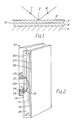
- FIG. 2 there is shown a conventional vertically oriented electrophoresis apparatus comprising an electrophoresis gel 10 sandwiched between a pair of plates 11, 12.
- Electrodes (not shown) are provided in order to produce a vertical current flow through the gel.
- Formed along the top edge of the gel are a plurality of spaced wells (not shown), each of which carry a separate sample to be analysed.
- Such samples may, for example, comprise the sub-samples which are produced when a DNA sample to be analysed is fragmented in a manner described above to give the four different sub-samples required to enable identification of the four bases.
- the gel acts as a skeletal foam in which are formed pores through which the material of the samples can pass under the influence of the electric current.
- the action of the current causes the fragments to migrate downwards through the gel, forming a distinct track emanating from each well, and travelling through the gel.
- the fragments formed by the fragmentation process tend to travel through in groups of identical length, those groups containing the shorter length fragments tending to travel faster through the gel than those containing the longer length fragments.
- the different groups tend to be bunched up near the top of the gel - i.e. nearest the well - but as they travel down the gel they become spread out because they are travelling at different speeds.
- the progress of the fragments through the gel is, of course, invisible to the naked eye but dyes can be used to enable visual monitoring of progress.
- the SPR detector for monitoring the progress of the electrophoresis is mainly mounted on a frame 13 which is slideable vertically with respect to the gel to effect scanning, as will be explained.
- the SPR detector comprises a light source 14 (for example, a laser), light detector 15 and concave reflectors 16, 17 all of which move up and down with the frame.
- the output from the light source is passed through a slit (not shown) or similar to produce a flat planar beam 18 extending horizontally - i.e. transversley across the expected tracks within the gel. Only the end of the beam is shown. It will be noted that the beam 18 has moderate depth A in the vertical direction.
- beam 18 Upon leaving the light source, beam 18 passes orthogonally through a plate 19 defining, with the plate 11, a chamber 20 in which the reflectors 16, 17 are situated.
- This chamber contains a liquid having the same refraction index as that of the plate 11 so that light passing across the boundary between chamber 20 and plate 11 at an angle is not refracted.
- Both plates 11 and 19 are made from transparent material.
- a metal layer formed on that side of plate 11 which faces the gel is a metal layer in the form of a mosaic of silver dots 21 formed as an X - Y array.
- a thin layer of insulating material such as polyimide covers the mosaic to prevent the conductive gel from electrically shorting the dots. This thin layer does not affect the operation of the detector.
- the light beam 18 from source 14 is appled to reflector 16 which is so shaped as to direct all of the light incident upon it to a single line 22 lying on that internal surface of the plate 11 against which the mosaic 21 is formed.
- the line 22 extends horizontally across the electrophoresis tracks and thus appears as a point in Figure 1.
- the input light beam between reflector 16 and line 22 thus takes the shape of a solid wedge of light, the two converging lines shown in the drawing representing the outer boundary of the converging solid beam.
- the angle of incidence of the incoming beam at the line 22 is such as to cause total internal reflection of the beam, the resultant internally reflected beam diverging from the line 22, again with a wedge shape, to be incident on the reflector 17 where the output light is reflected into a parallel beam which enters the detector 15.
- the detector 15 is connected to external circuitry (not shown) which analyses the detector output.
- the detector 15 comprises an array of separate sensitive areas extending horizontally across the gel in such a way that each detector monitors an individual silver dot in the horizontal (X) direction.
- the passage of fragments down the gel during electrophoresis can be monitored by observing the change in refractive index which occurs as the bunches of fragments of identical length travel down the gel.
- the frame 13 together with components 14 to 17 is vertically scanned up and down with respect to the gel by means not shown.
- the scanning movement of the frame 13 is synchronized with the detector output so that the associated circuitry can tell at any one time which line of dots in the vertical (Y) direction it is looking at.
- the scanning speed need only be relatively slow since the changes which occur during electrophoresis are themselves slow.
- the silver dots may be applied by any of the methods outlined above, or may be provided in the form of a throw-away sheet of silver dots on a disposable membrane which is optically coupled to the plate 11.
- the apparatus shown in Figure 2 may also be used to analyse the pattern of fragments in the gel after the electrophoresis test has been completed, rather than monitoring during electrophoresis, as described above. This obviously introduces a delay in obtaining the results, but may be preferred in some circumstances.
- the use of this technique also offers a way of improving the sensitivity of the system by drying out the gel after electrophoresis is completed. This is achieved by running the electrophoresis test in the normal way, and then removing plate 12 to expose that surface of the gel remote from silver mosaic layer 21 to the air.
- the gel thus dries out and shrinks: in so doing a typical 100 micron thick gel might reduce in thickness to as little as 4/5 microns if all the water is evaporated, and this thus concentrates all the DNA fragments into the 4 or 5 microns closest to the silver mosaic layer. In this way, the sensitivity is improved because the concentration of fragments which the SPR detector is effectively able to look at is much increased.
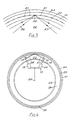
- FIG. 3 and 4 a second embodiment is illustrated, in which the gel 10 is confined in the annular gap between two concentric cylinders 23, 24 at least the inner (23) of which is made of transparent material.
- An annular chamber 26 defined between cylinders 23 and 25 contains a liquid having a refractive index equal to that of cylinder 23.
- the main components of the SPR detector are mounted on a frame 13 which in this case is rotatably mounted about the centre axis 29 of the cylinders.
- the light source 14, array detector 15 and reflectors 16, 17 all move with the frame.
- the reflectors 16, 17 are mounted within the index-matched fluid in the chamber 26 so that the wedge-shaped beams, shown under references 27 (input) and 28 (output) do not undergo refraction as they pass at an angle across the boundary between the chamber 26 and the cylinder 23. Extensive refraction of the input beam 18 from light source 14 is achieved by directing the output light beam in a radial direction. Similar comment applies to the beam entering the array detector 15.
- the inner cylinder 23 is formed, on its outer surface, with a mosaic of silver dots in the same manner as previously. In this case, the rows of dots extend axially and azimuthally of the cylinders. An insulating layer covers the dots to isolate them from the conductive effect of the gel.
- a plurality of separate wells are arranged in the gel along a line parallel with the axis 29.
- One of these wells is indicted diagrammatically under reference 30.
- Each well contains a separate sample or sub-sample for analysis.
- Electrodes (not shown) are arranged to cause an electric current flow through the gel in an azimuthal direction. During electrophoresis the fragments from the individual wells migrate in an anticlockwise azimuthal motion around the gel, forming a plurality of circular tracks, one extending from each well, in the manner described above.
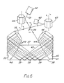
- a pencil light beam 31 from a light source 32 (for example, a laser) is reflected off a polygonal drum mirror 33 thence off a double-sided rotating mirror 34 and enters a plano-convex lens 35.
- a light source 32 for example, a laser
- the reflected beam scans across the input convex face of lens 35 in the plane of the drawing.
- Collimators (not shown) are preferably used to reduce stray light after the reflected beam has left the lens 35.
- Figures 5 and 6 show respectively the beginning and the end of the sweep of the reflected beam across the lens 35.
- the lens 35 is such as to bring all the reflected beams into parallel paths so that, whatever the instantaneous angle of mirror 34 the output from lens 35 is always in a particular direction.
- the prism 37 has a planar surface 38 on which is formed a metal layer in the form of a mosaic of silver dots 39 formed as an X-Y array.
- the X-Y array may for example comprise 5 rows and 10 columns - i.e. 50 dots in all. Illustrated in Figures 5 and 6 are the dots 39 of one of said 10 columns.
- a medium whose refractive index is to be measured On the remote side of the dots is a medium whose refractive index is to be measured.
- this medium could take the form of an electrophoresis gel.
- a thin insulating layer may be applied between the dots and the medium to prevent electrical interaction between the dots.
- the medium may take the form of a layer of specific or non-specific sensitive material, such as a layer of antibodies which is to react with a sample to be tested (not shown).
- the sensitive layer may be applied individually to each dot of the mosaic, or may be applied over the whole surface, possible with a thin electrically insulating layer between it and the mosaic if necessary.
- the metal layer may be a continuous layer, the surface being notionally broken down into pixels by electronic means, as will be explained later.
- the sides 40,41 of the prism 37 are angled, as shown, and the mirror 36 is arranged so that light reflected off it is incident orthogonally to the general plane of side 40.
- the side 40 is formed with a set of protruding convex elements 42 extending along the length of the prism. Each of these elements is associated with one row of dots 39 extending orthogonally to the plane of Figures 5 and 6 and acts to focus light passing across it to a point approximately centrally of the row of dots.
- the prism surface is blackened to prevent stray light entering and increasing the noise level.
- the electrical output from the detector 48 is passed to an associated computer or similar (not shown) so that the resultant signals can be analysed with reference to the rotation of the mirrors 33, 34 and 47.
- the rotation of the three mirrors will be synchronised and appropriate synchronising signals passed to the computer so that the detector knows what it is looking at.
- the metal layer is described as being in the form of a mosaic of metal dots, this is not essential, and the metal layer could take the form of separate stripes or even a continuous layer.
- the output signal from the detector 48 is gated in a gate 49 before being passed to a computer 50 for analysis.
- the clock output 51 from the computer is used to control the opening of the gate and also to control the drive means 52 for the mirror 34 and the drive means 53 for the mirror 33 (mirror 47 moves in synchronism with mirror 33).
- mirror 47 moves in synchronism with mirror 33.
- the clock pulses are arranged to open the gate 49 ten times for each single rotation of mirror 34, this Figure of ten corresponding to 2 x 5, bearing in mind that the mirror is double sided, and therefore causes two scans of the input light for each rotation.
- the clock pulses also control rotation of the drum mirrors 33, 47, for example by means of respective stepper motors, to step rotate by an amount sufficient to move the incident light to the next column each time the mirror 34 rotates through 180°.
- the gate 49 is opened 50 times, the mirror 34 rotates 5 times, and the drum mirrors 33/47 step rotate 10 times. This completes one scan of the area, and the drum mirrors 33/47 are now stepped on to the next facet, and the process repeated.
- the pulses applied to gate 49 are such as to open the gate for a period sufficient to allow through the complete SPR dip resulting from the scan across each of the 50 spots.
Abstract
A surface plasmon resonance (SPR) sensor for biochemical and similar testing on large area samples such as the gel (10) of an electrophoresis apparatus (13). The gel is sandwiched between a pair of plates (11, 12). Plate (11) is of transparent material and, sandwiched between itself and the gel is a metal layer comprising a mosaic (21) of silver dots. Light from a source (14) is directed via a reflector (16) and undergoes total internal reflection at the interface between plate (11) and metal layer (21). The reflected light is passed via reflector (17) to a light detector (15). The equipment is arranged so that SPR occurs at the metal layer, which resonance is critically dependent upon the refractive index of the gel (10). The structure comprising the light source 14 and detector 15, together with reflectors 16 and 17 is caused to scan across the gel surface to enable a two-dimensional representation of the changes in refractive index across the gel to be built up. This enables the progress of sequencing to be monitored.
Description
- This invention relates to surface plasmon resonance (SPR) sensors for use in biological, biochemical and chemical testing. The invention is particularly concerned with adaptions of such sensors to enable larger areas to be covered and thus enable the SPR technique to be used, for example, in applications such as sequencing.
- Sequencing of macromolecules, for example nucleic acids such as DNA, is usually carried out by biochemical fragmentation, followed by gel electrophoresis. Following electrophoresis the sequence is detected by exposure of the gel to autoradiographic film to give a two dimensional picture from which the sequence of individual nucleotide bases can be read. There are currently two main techinques used for fragmentation, the Maxam-Gilbert method involving the cleavage of the DNA molecule by a two-stage addition of chemicals, and the Sanger method involving the preparation of separate samples of dideoxynucleotide of each of the four bases C, G, A and T and then the growth of a complementary DNA strand to that of the DNA under test using an enzyme. Both techniques end up with four different sub-samples, enabling identification of the four bases, each containing fragments of different lengths. A radioactive or fluorescent label is attached to each fragment to enable detection of the sequence using autoradiography. In electrophoresis, the four different sub-samples, containing respective sets of labelled fragments are each placed in a separate well and thus generate a separate and distinct track across the gel as the electrophoresis proceeds. After the electrophoresis has finished, the gel is separated and typically dried and is then, in the case of the radioactive label, exposed to autoradiographic film to obtain an image of the pattern of labelled fragments of different length and belonging to different nucloetide groups.
- Autoradiography, whilst it can offer good sensitivity and resolution is an inconvenient technique, taking considerable skill to achieve good results, and is a fairly lengthy procedure, requiring many hours or even several weeks of exposure. Furthermore, separation of the gel after electrophoresis can lead to damage unless great care is taken, and the very necessary drying of the gel prior to exposure is also tricky since shrinking of the gel must be avoided if meaningful results are to be obtained.
- In the present invention, the requirement for autoradiography is eliminated by enabling direct monitoring of the gel using a surface plasmon resonance (SPR) detector. The SPR detector operates to detect changes in the refractive index of the gel across the gel surface. Areas of the gel where fragments are present will have a different refractive index to those where they are not and a "picture" of the gel surface can thus be built up. Although the use of gel will be assumed in this specification, the technique can in fact be used with gel-less and other forms of capillary electrophoresis.
- Monitoring can be in "real time" - i.e. as the electrophoresis test proceeds, or can be carried out on the gel after electrophoresis has been completed. In this latter case it may be advantageous to expose the gel to air after electrophoresis has finished so that the gel shrinks and thus concentrates the fragments into a smaller area which can be examined by the SPR detector.
- The use of surface plasmon resonance in connection with biosensors has been described in detail in our copending European patent application numbers 0305109 and 89300544.7, together with our copending British patent applications numbers 8811053.1, 8811054.9, 8811919.3 and 8813307.9.
- All of the techniques described in these applications can be applied to the teaching of the present invention.
- Surface plasmon resonance is the oscillation of the plasma of free electrons which exists at a metal boundary. These oscillations are affected by the refractive index of the material adjacent the metal surface and it is this that forms the basis of the sensor mechanism used in the present invention. Surface plasmon resonance may be achieved by using the evanescent wave which is generated when a p-polarised light beam is totally internally reflected at the boundary of a medium, e.g. glass, which has a high dielectric constant. A paper describing the technique has been published under the title "Surface plasmon resonance for gas detection and biosensing" by Lieberg, Nylander and Lundstrom in Sensors and Actuators, Vol. 4, page 299. Illustrated in Figure 1 of the accompanying drawings is a diagram of the equipment described in this paper. A beam 1 of light is applied from a laser source (not shown) onto an internal surface 2 of a
glass body 3. A detector (not shown) monitors the internally reflected beam 4. Applied to the external surface 2 ofglass body 3 is a thin film 5 of metal, for example gold or silver, and applied to the film 5 is a further thin film 6 of organic material containing antibodies. Asample 7 containing antigen is brought into contact with the antibody film 6 to thus cause a reaction between the antigen and the antibody. If binding occurs the refractive index of the layer 6 will change owing to the size of the antibody molecules and this change can be detected and measured using the surface plasmon resonance technique, as will now be explained. - Surface plasmon resonance can be experimentally observed, in the arrangement of Figure 1, by varying the angle of the incident beam 1 and monitoring the intensity of the internally reflected beam 4. At a certain angle of incidence the parallel component of the light momentum will match with the dispersion for surface plasmons at the
opposite surface 8 of the metal film. Provided that the thickness of metal film 5 is chosen correctly there will be an electromagnetic coupling between the glass/metal interface at surface 2 and the metal/antibody interface atsurface 8 as a result of surface plasmon resonance, and thus an attenuation in the reflected beam 4 at that particular angle of incidence. Thus, as the angle of incidence of beam 1 is varied, surface plasmon resonance is observed as a sharp dip in the intensity of the internally reflected beam 4 at a particular angle of incidence. The angle of incidence at which resonance occurs is affected by the refractive index of the material against the metal film 5 - i.e. the antibody layer 6 - and the angle of incidence corresponding to resonance is thus a direct measure of the state of the reaction between the antibody and the antigen. Increased sensitivity can be obtained by choosing an angle of incidence half way down the reflectance dip curve, where the response is substantially linear, at the beginning of the antibody/antigen reaction, and then maintaining that angle of incidence fixed and observing changes in the intensity of the reflected beam 4 with time. - A typical basic detector comprises the following components:
- 1) A source of electromagnetic radiation, most likely in or near the visible light region;
- 2) A block of transparent material such as glass on one surface of which is applied a thin film of metal, for example silver or gold, and on which is supported a medium to be tested in such a way that the metal film is sandwiched between the medium and the glass block;
- 3) Means for directing the electromagnetic radiation from the source into the transparent block in such a way that the radiation is subject to total internal reflection at that surface of the block to which the metal film is applied;
- 4) A detector for monitoring the intensity of the radiation which is totally internally reflected.
- The point of incidence of the incoming beam of radiation defines a small sensitive zone centred around the point. As the refractive index of the medium changes, the angle of incidence at which SPR occurs changes and, for a fixed angle of incidence, this manifests itself as an alteration in the intensity of the totally internally reflected beam, as detected by the detector. A significant improvement in signal/noise ratio can be achieved, however, by monitoring the whole of the dip resulting from surface plasmon resonance. This may be achieved either by rapidly scanning the incoming beam of radiation across the angles of incidence which result in surface plasmon resonance, such as described in our application 8811053.1, or by utilising the so called "fan beam" as described in our copending European patent application 0305109. In a variant of the fan beam, a line point of incidence is formed using a wedge beam, possibly in conjuction with a hemicylinder, as described in the aforementioned European patent application.
- The difficulty in the known apparatus is that the sensitive zone centred around the point or line of incidence is very limited in extent and therefore where a large area needs to be monitored, the existing equipment cannot be used. In the present invention, this problem is addressed by providing means for moving the point or line of incidence to effectively provide two dimensional coverage of an area. The movement of the point or line is synchronised with the detector so that, at any one instant of time, the detector knows at which point on the area it is looking.
- The metal film is assumed to take the form of a continuous layer. However, in certain circumstances, as will be explained later, it may be desirable to divide the metal film into separate isolated areas whose size depends upon the required resolution and the circumstances of use. In a preferred embodiment, the metal film takes the form of a mosaic of mutually isolated dots of metallisation. The point or line of incidence is moved across said isolated areas, each of which effectively becomes a separate SPR detector.
- A two dimensional area may be covered either by raster scanning of a point of incidence or by one-dimensional scanning of a suitable line of incidence. Scanning may be effected either by a moving mirror system, or by mechanically scanning a first assembly comprising the radiation source, detector and radiation directing means with respect to a second assembly comprising the glass block and metal film in such a way that the point or line of incidence remains always at the interface between the glass block and the metal film. Other variations will be apparent.
- It will be seen that, by incorporating these techniques, it is possible to monitor a two dimensional surface of substantial size. A picture of the events within the medium can thus be built up in real time.
- In an embodiment of the invention, the medium is an electrophoresis gel forming part of an electrophoresis apparatus. As the fragments proceed through the gel during the process of electrophoresis, the refractive index of the gel changes locally, and this change can be monitored by the apparatus of the present invention. The output signal from the detector is passed to a microcomputer which builds up a pattern of the refractive index variations over the scanned area to follow the progress of the fragments.
- The discontinuous metal film effectively provides a plurality of independent sensitive zones which are individually monitored by the SPR detector as it scans with respect to the gel. The nature of these discontinuities will of course depend on the form of scanning used. For two dimensional raster-type scanning the metal film takes the form of the aforementioned mosaic of metal, for example silver, dots. Each of these dots will thus effectively supply a pixel of information to build up a complete picture, ih real time, of the progress of sequencing.
- Such a two-dimensional multi-dot system can simultaneously monitor a plurality of tracks through the gel and can look at the whole of the gel surface. A minimum of four such tracks is needed to fully characterise a particular DNA sample, but there is no reason why a number of separate samples should not be monitored simultaneously: the number is limited only by the number of sets of four lanes that can be fitted in the scanning width.
- Current standards of resolution for such scanners will allow resolution of less than 100 microns which is more than adequate for gel sequencing. Surface plasmon resonance will operate on silver dot sizes of 100 microns diameter or less.
- In practice, the mosaic of dots or other discontinuous metal film is covered by a thin insulating layer, for example of polyimide, in order to prevent interaction between individual dots due to the gel which would otherwise be applied directly to the metal film.
- In an alternative embodiment of the invention the medium comprises two components of a biological, biochemical or chemical interaction. A first of these components will normally comprise or be attached to the metal film. The second component is an entity within a sample to be tested. For example, the first component could be an antibody attached to the metal layer and the second component a corresponding antigen within a sample. In general, however, any sensitive material, whether specific or non-specific may be attached to the metal layer for interaction with a corresponding entity in the sample. Indeed, the metal layer itself may in some circumstances act as the first component since this will act as a non-specific sensitive material with which certain classes of entity within a sample may interact.
- The first component may be applied as a continuous layer over the metal film; if the metal film is discontinuous, different areas of metal may have different sensitive materials applied thereto, or they may all have the same sensitive material attached. With a continuous metal layer, the first component may be applied all over, or in separate smaller areas which can be individually scanned as the line or point of incidence passes over them. In this way, a large number of tests can be carried out, in effect, simultaneously. Such smaller sensitive areas may all comprise the same sensitive material, or it may be different, so that a single sample can be subjected to several different tests at a time. The sample may be arranged to flood over the whole area, or may be channelled so as to come into contact with only selected sensitive areas. This enables several samples to be tested simultaneously and/or a reference test on a control sample to be carried out simultaneously with that on a main sample.
- If raster (line) scanning is used, it is preferred to position such sensitive areas under the path of the point or line of incidence so that, as scanning takes place, the tests can be monitored by reference to the output of the radiation detector which can be related to the particular X-Y position of the test.
- The metal film material is commonly silver or gold, usually applied by evaporation. The film needs to be as uniform as possible in order to cater for minute movement in the point of incidence of the incoming beam. It is assumed that a structured metal film will give the best resonance and there are various ways in which the transparent plate to which it is applied can be pretreated to improve the performance of the metal film and in particular to control the natural tendency of such films to form discontinuous islands;
- 1. Immersion in molten metal nitrates and other molten salts. This has the effect of introducing ions into the surface in a manner which can be structured and which can act as foci for island formation.
- 2. Ion bombardment of cold or hot glass to introduce nucleating sites. The removal of the more mobile ions has been demonstrated to reduce the thickness at which the evaporated film becomes continuous.
- 3. Electroless plating or electroplating over lightly evaporated films (0 to 100 angstroms thick). Electroless plated films survive to a greater thickness than evaporated films and could form more stable nuclei for subsequent coating.
- 4. Evaporating on to electroless plated films. The electroless plated films have a stronger tendency to an island structure and to bigger islands with greater spacing than evaporating films. This could be of advantage in tuning to light of a prescribed wavelength.
- Coating performance can also be improved by:
- 1. Controlling the surface temperature of the transparent plate during coating. Using a higher temperature substrate increases the islands' size and the spacing between them and conversely.
- 2. Evaporating in the presence of a magnetic or electrostatic field or electron emission device to control the ion content of the vapour stream. The state of charge of the substrate is know to affect the island structure.
- 3. Controlling the angle of incidence of the evaporated vapour stream relative to the surface of the plate. The mobility of the evaporated atoms and hence their ability to form bigger islands is greater when the momentum of the atoms relative to the glass surface is increased.
- In order that the invention may be better understood, some embodiments thereof will now be described by way of example only and with reference to the accompanying drawings in which:-
- Figure 1 is a diagram of a known experimental arrangement for demonstrating the surface plasmon resonance effect;
- Figure 2 is a diagrammatic perspective view of a planar SPR sensor constructed in accordance with the invention;
- Figure 3 is a diagrammatic partial plan view of a cylindrical SPR sensor constructed in accordance with the invention;
- Figure 4 is a view similar to Figure 3, but showing the whole of the apparatus on a smaller scale.
- Figures 5 and 6 are diagrammatic views of an alternative embodiment of the SPR sensor of the invention;
- Figure 7 is a perspective view of the apparatus of Figures 5 and 6; and
- Figure 8 is a block diagram showing one example of the manner in which the output of the SPR detector is synchronised with the mirror motion in the apparatus of Figures 5 to 7.
- Referring firstly to Figure 2 there is shown a conventional vertically oriented electrophoresis apparatus comprising an
electrophoresis gel 10 sandwiched between a pair ofplates - The SPR detector for monitoring the progress of the electrophoresis is mainly mounted on a
frame 13 which is slideable vertically with respect to the gel to effect scanning, as will be explained. The SPR detector comprises a light source 14 (for example, a laser),light detector 15 andconcave reflectors planar beam 18 extending horizontally - i.e. transversley across the expected tracks within the gel. Only the end of the beam is shown. It will be noted that thebeam 18 has moderate depth A in the vertical direction. - Upon leaving the light source,
beam 18 passes orthogonally through aplate 19 defining, with theplate 11, achamber 20 in which thereflectors plate 11 so that light passing across the boundary betweenchamber 20 andplate 11 at an angle is not refracted. Bothplates - Formed on that side of
plate 11 which faces the gel is a metal layer in the form of a mosaic ofsilver dots 21 formed as an X - Y array. A thin layer of insulating material such as polyimide covers the mosaic to prevent the conductive gel from electrically shorting the dots. This thin layer does not affect the operation of the detector. - In operation, the
light beam 18 fromsource 14 is appled toreflector 16 which is so shaped as to direct all of the light incident upon it to asingle line 22 lying on that internal surface of theplate 11 against which the mosaic 21 is formed. Theline 22 extends horizontally across the electrophoresis tracks and thus appears as a point in Figure 1. The input light beam betweenreflector 16 andline 22 thus takes the shape of a solid wedge of light, the two converging lines shown in the drawing representing the outer boundary of the converging solid beam. - The angle of incidence of the incoming beam at the
line 22 is such as to cause total internal reflection of the beam, the resultant internally reflected beam diverging from theline 22, again with a wedge shape, to be incident on thereflector 17 where the output light is reflected into a parallel beam which enters thedetector 15. Thedetector 15 is connected to external circuitry (not shown) which analyses the detector output. - The
detector 15 comprises an array of separate sensitive areas extending horizontally across the gel in such a way that each detector monitors an individual silver dot in the horizontal (X) direction. - If conditions are correct and in particular if the range of angles spanned by the
incident beam 18 is correct, then surface plasmon resonance will occur, this manifesting itself as a sharp dip in the intensity of the output beam as detected by the array detector 15 (see above). The effect of a change in the refractive index in the medium - in this case the gel 10 - behind theplate 11 is to cause the angle of incidence at which surface plasmon resonance occurs to change. If the whole dip is being monitored by ensuring that the span of the angles of incidence of converginginput beam 18 cover the resonant condition, then a change in refractive index in thegel 10 translates at thedetector 15 into a rapid change in output intensity. - By this means, the passage of fragments down the gel during electrophoresis can be monitored by observing the change in refractive index which occurs as the bunches of fragments of identical length travel down the gel.
- In order to obtain a real time analysis of the whole gel surface as electrophoresis proceeds, the
frame 13 together withcomponents 14 to 17 is vertically scanned up and down with respect to the gel by means not shown. The scanning movement of theframe 13 is synchronized with the detector output so that the associated circuitry can tell at any one time which line of dots in the vertical (Y) direction it is looking at. The scanning speed need only be relatively slow since the changes which occur during electrophoresis are themselves slow. - Alternative optical geometrics (not shown) may be envisaged where the incoming wedge-shaped light beam is reflected off a rotating polygon similar to that used in document scanner and copiers to give a horizontal line focus on the silver dots.
- The silver dots may be applied by any of the methods outlined above, or may be provided in the form of a throw-away sheet of silver dots on a disposable membrane which is optically coupled to the
plate 11. - The apparatus shown in Figure 2 may also be used to analyse the pattern of fragments in the gel after the electrophoresis test has been completed, rather than monitoring during electrophoresis, as described above. This obviously introduces a delay in obtaining the results, but may be preferred in some circumstances. The use of this technique also offers a way of improving the sensitivity of the system by drying out the gel after electrophoresis is completed. This is achieved by running the electrophoresis test in the normal way, and then removing
plate 12 to expose that surface of the gel remote fromsilver mosaic layer 21 to the air. The gel thus dries out and shrinks: in so doing a typical 100 micron thick gel might reduce in thickness to as little as 4/5 microns if all the water is evaporated, and this thus concentrates all the DNA fragments into the 4 or 5 microns closest to the silver mosaic layer. In this way, the sensitivity is improved because the concentration of fragments which the SPR detector is effectively able to look at is much increased. - Other ways of encouraging the fragments to move towards the silver layer might be conceived - for example the electric current flow could be distorted to cause the fragments to move towards the silver film layer, thus increasing sensitivity.
- Referring now to Figure 3 and 4 a second embodiment is illustrated, in which the
gel 10 is confined in the annular gap between twoconcentric cylinders concentric cylinder 25, also of transparent material, lies inwardly ofcylinders plate 19 of the previous embodiment. Anannular chamber 26 defined betweencylinders cylinder 23. As before the main components of the SPR detector are mounted on aframe 13 which in this case is rotatably mounted about thecentre axis 29 of the cylinders. Thelight source 14,array detector 15 andreflectors reflectors chamber 26 so that the wedge-shaped beams, shown under references 27 (input) and 28 (output) do not undergo refraction as they pass at an angle across the boundary between thechamber 26 and thecylinder 23. Extensive refraction of theinput beam 18 fromlight source 14 is achieved by directing the output light beam in a radial direction. Similar comment applies to the beam entering thearray detector 15. - The
inner cylinder 23 is formed, on its outer surface, with a mosaic of silver dots in the same manner as previously. In this case, the rows of dots extend axially and azimuthally of the cylinders. An insulating layer covers the dots to isolate them from the conductive effect of the gel. - A plurality of separate wells are arranged in the gel along a line parallel with the
axis 29. One of these wells is indicted diagrammatically underreference 30. Each well contains a separate sample or sub-sample for analysis. Electrodes (not shown) are arranged to cause an electric current flow through the gel in an azimuthal direction. During electrophoresis the fragments from the individual wells migrate in an anticlockwise azimuthal motion around the gel, forming a plurality of circular tracks, one extending from each well, in the manner described above. - As electrophoresis proceeds, progress is monitored by rotating the
frame 13 to scan the whole area of the electrophoresis gel. As before, the scanning rate does not need to be high in view of the relatively slow progress of the electrophoresis. - Referring now to Figures 5, 6 and 7 there is shown a second embodiment of the invention in which scanning takes place by movement of mirrors.
- A
pencil light beam 31 from a light source 32 (for example, a laser) is reflected off apolygonal drum mirror 33 thence off a double-sidedrotating mirror 34 and enters a plano-convex lens 35. As themirror 34 rotates, the reflected beam scans across the input convex face oflens 35 in the plane of the drawing. Collimators (not shown) are preferably used to reduce stray light after the reflected beam has left thelens 35. By way of illustration, Figures 5 and 6 show respectively the beginning and the end of the sweep of the reflected beam across thelens 35. Thelens 35 is such as to bring all the reflected beams into parallel paths so that, whatever the instantaneous angle ofmirror 34 the output fromlens 35 is always in a particular direction. This is represented in Figures 5 and 6 by a series of parallel lines although, of course, only a single beam is passing at any one instant of time. The beam leaving thelens 35 is incident on aplane mirror 36 which reflects the beam into aprism 37 made of transparent material such as glass. As will be clear from Figure 7, the plano-convex lens 35,mirror 36, andprism 37 are elongate in a direction orthogonal to the plane of Figures 5 and 6. The reason for this will become apparent. - The
prism 37 has aplanar surface 38 on which is formed a metal layer in the form of a mosaic ofsilver dots 39 formed as an X-Y array. As shown, the X-Y array may for example comprise 5 rows and 10 columns - i.e. 50 dots in all. Illustrated in Figures 5 and 6 are thedots 39 of one of said 10 columns. - On the remote side of the dots is a medium whose refractive index is to be measured. For example, as in the previous embodiment, this medium could take the form of an electrophoresis gel. If the medium is electrically conductive, then a thin insulating layer may be applied between the dots and the medium to prevent electrical interaction between the dots. Alternatively the medium may take the form of a layer of specific or non-specific sensitive material, such as a layer of antibodies which is to react with a sample to be tested (not shown). The sensitive layer may be applied individually to each dot of the mosaic, or may be applied over the whole surface, possible with a thin electrically insulating layer between it and the mosaic if necessary. As with the previous embodiment, the metal layer may be a continuous layer, the surface being notionally broken down into pixels by electronic means, as will be explained later.
- The
sides prism 37 are angled, as shown, and themirror 36 is arranged so that light reflected off it is incident orthogonally to the general plane ofside 40. Theside 40 is formed with a set of protrudingconvex elements 42 extending along the length of the prism. Each of these elements is associated with one row ofdots 39 extending orthogonally to the plane of Figures 5 and 6 and acts to focus light passing across it to a point approximately centrally of the row of dots. Thus, as themirror 36 rotates, the light moves across eachelement 42 in turn. In between the elements, the prism surface is blackened to prevent stray light entering and increasing the noise level. - As the light beam passes across each
element 42, it is refracted to the aforementioned central point with a varying angle of incidence. It is arranged that this range covers those that give rise to surface plasmon resonance at thesurface 38. The resultant internally reflectedbeam 43 passes through a corresponding one of a similar plurality ofconvex elements 44 formed on theside 41 of the prism. Aplane mirror 45 and plano-convex lens 46 corresponding respectively to mirror 36 and plano-convex lens 35 act to bring the internally reflected beam onto the reflective rear side ofmirror 34 at which it is reflected, via a secondpolygonal drum mirror 47, to alight detector 48. Surface plasmon resonance occurring atsurface 38 is viewed as a dip in the strength of the internally reflectedbeam 43, as measured at thedetector 48. As the incident light beam scans across those angles of incidence which result in surface plasmon resonance occurring, the whole dip can be viewed by analysis of the output signal of thedetector 48. As themirror 34 rotates, the light is applied to theelements 42 one by one and is brought to a focus on thedots 39, likewise one by one. However, only the single column ofdots 39 which are in the plane of Figures 5 and 6 will be covered. To cover the remaining columns ofdots 39 thepolygonal drum mirror 33 is rotated by a small amount for each 180° rotation of themirror 34. While the input beam is being scanned across thelens 35 themirror 33 is stationary. In between scans, however, themirror 33 is stepped around by a small angle to thereby cause the input beam, on its next scan across thelens 35 to be incident on the next adjacent column of dots. In this way, all the dots can be covered by incrementing themirror 33 around for each 180° of rotation of mirror 34 (mirror 34 is double-sided). For this purpose,mirror 33 needs only be a plane mirror, but the use of a polygonal drum mirror is mechanically advantageous because it eliminates the large return movement which is necessary between each full field scan - instead of returning through a large angle to its start position, the mirror is simply turned to the next facet, and the process repeated. Although a six-sided mirror is shown, this has no particular significance and different numbers of sides could be used. On the output side,polygonal drum mirror 47 is step rotated in synchronism withmirror 33 to bring the incoming beam to thedetector 48 from whichever dot 39 it has been reflected. - It will be appreciated that Figures 5, 6 and 7 are very diagrammatic in nature. For the sake of clarity, details of supporting structure, drive motors etc., are not given since they will be apparent to those skilled in the art. Also, the
dots 39 are not spaced fromsurface 38, as shown, but are positioned directly on the surface. - The electrical output from the
detector 48 is passed to an associated computer or similar (not shown) so that the resultant signals can be analysed with reference to the rotation of themirrors - Although in all of the above-described embodiments the metal layer is described as being in the form of a mosaic of metal dots, this is not essential, and the metal layer could take the form of separate stripes or even a continuous layer.
- In the latter case, the area being examined is still divided into small cells or pixels for the purpose of analysis, but this division is carried out electronically, rather than, in effect, mechanically. To achieve this, the output signal from the detector must be synchronised with the mechanical scanning movements so that the instantaneous output from the detector can be correctly related to a particular X-Y position on the area being scanned. Figure 8 illustrates, for the apparatus of Figures 5 to 7, one way of achieving this.
- Referring to Figure 8, the output signal from the
detector 48 is gated in agate 49 before being passed to acomputer 50 for analysis. Theclock output 51 from the computer is used to control the opening of the gate and also to control the drive means 52 for themirror 34 and the drive means 53 for the mirror 33 (mirror 47 moves in synchronism with mirror 33). Thus, if we take the previous example of 50 dots in an array of 5 rows and 10 columns, it is assumed that each of the 5 rows corresponds to one of theelements 42/44 and that the drum mirrors 33/47 rotate in 10 small steps, each step being sufficient to move the incident light beam to the next column. When all of the 10 columns have been scanned, themirrors gate 49 ten times for each single rotation ofmirror 34, this Figure of ten corresponding to 2 x 5, bearing in mind that the mirror is double sided, and therefore causes two scans of the input light for each rotation. The clock pulses also control rotation of the drum mirrors 33, 47, for example by means of respective stepper motors, to step rotate by an amount sufficient to move the incident light to the next column each time themirror 34 rotates through 180°. Thus, for each clock pulse, thegate 49 is opened 50 times, themirror 34 rotates 5 times, and the drum mirrors 33/47 step rotate 10 times. This completes one scan of the area, and the drum mirrors 33/47 are now stepped on to the next facet, and the process repeated. The pulses applied togate 49 are such as to open the gate for a period sufficient to allow through the complete SPR dip resulting from the scan across each of the 50 spots. Thus, for each scan, we get 50 SPR dips resulting from each of the points at which the incoming beam is incident, and this signal can be analysed by the computer to enable the SPR analysis of the whole area. Repeated scans of the area enable changes with time to be studied. - It will be seen that, by relating the movement of the beam with the output of the detector, such as shown in Figure 8, a continuous metal layer can be employed in place of the mosaic of
dots 39. In certain circumstances, it may be necessary or desirable to incorporate thin insulating film (see above) over the metal layer so that the medium being measured is electrically isolated from the metal layer. This would be desirable where, for example, the medium takes the form of an electrophoresis gel which relies for its operation on the passage of current therethrough. If no insulation were present, a continuous metal layer would make it virtually impossible to pass the necessary current through the gel to make the electrophoresis apparatus function.
Claims (23)
1. A surface plasmon resonance (SPR) sensor comprising a source of electromagnetic radiation, a block of transparent material against one surface of which is positioned a thin film of metal and against which film is positioned a medium to be tested in such a way that the metal film lies between the medium and the transparent block, means for directing the electromagnetic radiation from the source into the transparent block in such a way that the radiation is subject to total internal reflection at said one surface of the block, scanning means for scanning the radiation beam incident on said surface across said surface in order to obtain a two-dimensional representation of the variation of refractive index across said medium, and a radiation detector for monitoring the intensity of the radiation which is totally internally reflected.
2. A sensor as claimed in Claim 1 wherein a membrane of dielectric material is positioned against said one surface of said block of transparent material and said metal film is applied to that surface of the membrane remote from the block so that the membrane is interposed between the block and the metal film, and wherein the refractive index of the block is higher than that of the membrane such that total internal reflection takes place at the interface between the block and the membrane.
3. A sensor claimed in Claim 1 wherein said metal film is applied directly to said one surface of the block.
4. A sensor as claimed in any one of claims 1 to 3 wherein said metal film is comprised of a plurality of discontinuous areas of metal film.
5. A sensor as claimed in Claim 4 wherein said metal film takes the form of a two-dimensional mosaic of metal film dots.
6. A sensor as claimed in any one of the preceding claims wherein said medium is an electrophoresis medium forming part of an electrophoresis apparatus for the sequencing of macromolecules.
7. A sensor as claimed in any one of claims 1 to 5 wherein said medium comprises two components of a biological, biochemical or chemical interaction, wherein a first component is attached to the metal film, and a second component takes the form of a sample to be analysed which is brought into contact with the first component.
8. A sensor as claimed in claim 7 wherein said first component is attached to the metal film in the form of a plurality of isolated areas of the component and wherein said scanning means is operable to scan said radiation beam across said isolated areas so that the interaction between the second component and the first in each area can be monitored in sequence.
9. A sensor as claimed in any one of the preceding claims wherein the radiation is totally internally reflected at a point on said surface, and wherein said scanning means is operable to two-dimensionally raster scan said point across the surface.
10. A sensor as claimed in any one of claims 1 to 8 wherein the incident radiation has a wedge shape, resulting in a line of incidence at said surface, and wherein said scanning means is operable to one-dimensionally scan said time of incidence in a direction orthogonal to its length to thus cover said surface.
11. A sensor as claimed in any one of the preceding claims wherein a first structure comprising said radiation source, radiation directing means and radiation detector is moveably mounted with respect to a second structure comprising said transparent block, metal film and medium, and wherein said scanning means is operable to effect scanning movement of said first structure with respect to said second structure so as to scan the radiation beam across said one surface of the transparent block.
12. A sensor as claimed in claim 11 wherein the medium against that surface of the block of transparent material through which said electromagnetic radiation enters the block is a liquid medium.
13. A sensor claimed in claim 12 wherein said liquid medium has a refractive index equal to that of said block.
14. A sensor as claimed in either one of claims 12 or 13 wherein said means for directing the electromagnetic radiation is positioned within said liquid medium.
15. A sensor as claimed in any one of claims 1 to 10 wherein said scanning means comprises moveable mirror means for scanning the radiation across said one surface of the transparent block.
16. A sensor as claimed in claim 14 wherein said scanning means comprises two moveable mirrors:
a first mirror which is moveable to scan the radiation over said one surface in a first direction;
a second mirror which is moveable to scan the radiation over said one surface in a second direction orthogonal to the first;
and wherein drive means are provided for each mirror, said drive means being controlled by control means which are operable to step rotate said second mirror by a small amount each time said first mirror has scanned once across the surface in the first direction so that the surface is raster scanned by the radiation.
17. A sensor as claimed in either one of claims 15 or 16 further comprising means for relating the movement of said mirrors with the output from said radiation detector to enable a two-dimensional representation of the medium to be generated.
18. Sequencing apparatus comprising means for analysing a sample containing fragments by electrophoresis, and detector means for detecting the pattern of fragments distributed within the electrophoresis medium, said detector means comprising a detector which utilises the phenomenon of surface plasmon resonance to monitor the pattern of fragments by virtue of the change in refractive index which occurs in those parts of the electrophoresis medium in which fragments are present.
19. Sequencing apparatus as claimed in claim 18 wherein the detector means is moveable with respect to the electrophoresis medium, and means are provided for scanning the detector means over the medium.
20. Sequencing apparatus as claimed in either one of claims 18 or 19 wherein the electrophoresis medium is a gel.
21. Sequencing apparatus as claimed in any one of claims 18 to 20 wherein said detector means comprises a source of electromagnetic radiation, a block of transparent material facing one surface of which is positioned a thin film of metal and against which film is positioned the electrophoresis medium in such a way that the metal film lies between the gel and the glass block, means for directing the electromagnetic radiation from the source into the transparent block in such a way that the radiation is subject to total internal reflection at said one surface of the block, and a radiation detector for monitoring the intensity of the radiation which is totally internally reflected.
22. A method of sequencing comprising subjecting a sample containing fragments to electrophoresis to thereby distribute the fragments along the electrophoresis medium according to their size and/or charge and detecting, using the phenomenon of surface plasmon resonance, the pattern of distribution of the fragments within the medium by virtue of the change in refractive index which occurs in those parts of the medium in which fragments are present.
23. A method as claimed in claim 22 wherein detecting is carried out by scanning a detector means across the medium.
Applications Claiming Priority (6)
| Application Number | Priority Date | Filing Date | Title |
|---|---|---|---|
| GB8811053 | 1988-05-10 | ||
| GB8811054 | 1988-05-10 | ||
| GB888811053A GB8811053D0 (en) | 1988-05-10 | 1988-05-10 | Biological sensors |
| GB888811054A GB8811054D0 (en) | 1988-05-10 | 1988-05-10 | Biological sensors |
| GB888821336A GB8821336D0 (en) | 1988-09-12 | 1988-09-12 | Apparatus for biochemical sequencing |
| GB8821336 | 1988-09-12 |
Publications (1)
| Publication Number | Publication Date |
|---|---|
| EP0341928A1 true EP0341928A1 (en) | 1989-11-15 |
Family
ID=27263901
Family Applications (1)
| Application Number | Title | Priority Date | Filing Date |
|---|---|---|---|
| EP89304572A Withdrawn EP0341928A1 (en) | 1988-05-10 | 1989-05-05 | Improvements relating to surface plasmon resonance sensors |
Country Status (4)
| Country | Link |
|---|---|
| US (1) | US5035863A (en) |
| EP (1) | EP0341928A1 (en) |
| JP (1) | JPH0217431A (en) |
| AU (1) | AU611291B2 (en) |
Cited By (16)
| Publication number | Priority date | Publication date | Assignee | Title |
|---|---|---|---|---|
| WO1991017427A1 (en) * | 1990-05-02 | 1991-11-14 | Nederlandse Organisatie Voor Toegepast-Natuurwetenschappelijk Onderzoek Tno | Method for determining a specific ligand in a fluid sample with the aid of an evanescent field, and also a component of the requisite measuring equipment suitable for this purpose |
| WO1992005426A1 (en) * | 1990-09-13 | 1992-04-02 | Amersham International Plc | Biological sensors |
| WO1993004357A1 (en) * | 1991-08-20 | 1993-03-04 | Pharmacia Biosensor Ab | Assay method |
| EP0805347A2 (en) * | 1996-04-30 | 1997-11-05 | Fuji Photo Film Co., Ltd. | Surface plasmon sensor |
| EP0863395A2 (en) * | 1997-02-07 | 1998-09-09 | Fuji Photo Film Co., Ltd. | Surface plasmon sensor |
| DE19805809A1 (en) * | 1998-02-12 | 1999-09-02 | Biotul Bio Instr Gmbh | Transducer for determining surface plasmon resonances using spatially or time-modified layers for surface plasmon resonance spectroscopy |
| DE19829086A1 (en) * | 1998-06-30 | 2000-01-13 | Univ Dresden Tech | Optical measuring method for ultra-thin layers e.g. polymer films |
| WO2001063256A1 (en) * | 2000-02-22 | 2001-08-30 | Graffinity Pharmaceutical Design Gmbh | Spr sensor system |
| WO2003034046A1 (en) * | 2001-10-17 | 2003-04-24 | Vir A/S | Surface plasmon resonance sensor |
| WO2003046526A1 (en) * | 2001-11-28 | 2003-06-05 | Graffinity Pharmaceuticals Ag | Surface plasmon resonance (spr) sensor surface support |
| US6795192B2 (en) | 2000-02-22 | 2004-09-21 | Graffinity Pharmaceutical Design Gmbh | SPR sensor and SPR sensor array |
| WO2004113880A2 (en) * | 2003-06-23 | 2004-12-29 | Canon Kabushiki Kaisha | Chemical sensor and chemicalsensor apparatus |
| DE10324973A1 (en) * | 2003-05-27 | 2004-12-30 | Fraunhofer-Gesellschaft zur Förderung der angewandten Forschung e.V. | Arrangement and method for the optical detection of chemical, biochemical molecules and / or particles contained in samples |
| US7443507B2 (en) | 2002-12-25 | 2008-10-28 | Bio-Rad Laboratories Inc. | Surface plasmon resonance sensor |
| EP1871902B1 (en) * | 2005-04-18 | 2010-10-27 | Illumina Cambridge Limited | Method and device for nucleic acid sequencing using a planar wave guide |
| US8530243B2 (en) | 2009-04-20 | 2013-09-10 | Bio-Rad Laboratories Inc. | Non-scanning SPR system |
Families Citing this family (84)
| Publication number | Priority date | Publication date | Assignee | Title |
|---|---|---|---|---|
| US4935346A (en) | 1986-08-13 | 1990-06-19 | Lifescan, Inc. | Minimum procedure system for the determination of analytes |
| GB8801807D0 (en) * | 1988-01-27 | 1988-02-24 | Amersham Int Plc | Biological sensors |
| US5547839A (en) | 1989-06-07 | 1996-08-20 | Affymax Technologies N.V. | Sequencing of surface immobilized polymers utilizing microflourescence detection |
| JPH03233166A (en) * | 1990-02-06 | 1991-10-17 | Suzuki Motor Corp | Oxygen enriching device for internal combustion engine |
| JPH03117749U (en) * | 1990-03-15 | 1991-12-05 | ||
| US5172182A (en) * | 1991-05-31 | 1992-12-15 | Sting Donald W | Internal reflectance element with very small sample contacting surface |
| US5395587A (en) * | 1993-07-06 | 1995-03-07 | Smithkline Beecham Corporation | Surface plasmon resonance detector having collector for eluted ligate |
| GB9320305D0 (en) * | 1993-10-01 | 1993-11-17 | Kodak Ltd | Production of carriers for surface plasmin resonance |
| US5955153A (en) * | 1993-10-01 | 1999-09-21 | Johnson & Johnson Clinical Diagnostics, Inc. | Production of carriers for surface plasmon resonance |
| GB9320310D0 (en) * | 1993-10-01 | 1993-11-17 | Kodak Ltd | Production of carriers for surface plasmon resonance |
| JP3390063B2 (en) * | 1993-10-25 | 2003-03-24 | 日本分光株式会社 | Optical system for high sensitivity reflection measurement equipment |
| DE4345225A1 (en) * | 1993-11-15 | 1995-05-18 | Hoffmann La Roche | Arrangement for analysis of substances on surface of optical sensor |
| US5606633A (en) * | 1995-06-26 | 1997-02-25 | American Research Corporation Of Virginia | Chemical detector employing surface plasmon resonance excited using an optical waveguide configured as an asymmetric waveguide coupler |
| WO1997015820A1 (en) * | 1995-10-25 | 1997-05-01 | University Of Washington | Surface plasmon resonance electrode as chemical sensor |
| JP4043538B2 (en) * | 1996-04-25 | 2008-02-06 | 富士フイルム株式会社 | Surface plasmon sensor |
| US5852229A (en) * | 1996-05-29 | 1998-12-22 | Kimberly-Clark Worldwide, Inc. | Piezoelectric resonator chemical sensing device |
| US6020047A (en) * | 1996-09-04 | 2000-02-01 | Kimberly-Clark Worldwide, Inc. | Polymer films having a printed self-assembling monolayer |
| JPH1078391A (en) * | 1996-09-04 | 1998-03-24 | Fuji Photo Film Co Ltd | Surface plasmon sensor |
| JP3999292B2 (en) * | 1996-09-04 | 2007-10-31 | 富士フイルム株式会社 | Surface plasmon sensor |
| US5846843A (en) * | 1996-11-18 | 1998-12-08 | The University Of Toledo | Sensor using long range surface plasmon resonance with diffraction double-grating |
| US5922550A (en) * | 1996-12-18 | 1999-07-13 | Kimberly-Clark Worldwide, Inc. | Biosensing devices which produce diffraction images |
| US6048623A (en) * | 1996-12-18 | 2000-04-11 | Kimberly-Clark Worldwide, Inc. | Method of contact printing on gold coated films |
| JP3399804B2 (en) * | 1997-02-26 | 2003-04-21 | 富士写真フイルム株式会社 | Surface plasmon sensor |
| US6180288B1 (en) | 1997-03-21 | 2001-01-30 | Kimberly-Clark Worldwide, Inc. | Gel sensors and method of use thereof |
| AU1060099A (en) * | 1997-06-10 | 1999-01-25 | American Research Corporation Of Virginia | Detection of chemical agent materials using a sorbent polymer and fluores cent probe |
| US5955378A (en) * | 1997-08-20 | 1999-09-21 | Challener; William A. | Near normal incidence optical assaying method and system having wavelength and angle sensitivity |
| US6454925B1 (en) | 1997-08-25 | 2002-09-24 | Shimadzu Corporation | Device for electrophoresis and component therefor |
| US5994150A (en) | 1997-11-19 | 1999-11-30 | Imation Corp. | Optical assaying method and system having rotatable sensor disk with multiple sensing regions |
| US6060256A (en) | 1997-12-16 | 2000-05-09 | Kimberly-Clark Worldwide, Inc. | Optical diffraction biosensor |
| US6161437A (en) * | 1998-04-09 | 2000-12-19 | Georgia Tech Research Corporation | Method and apparatus for evaluating an analyte |
| US5986762A (en) * | 1998-06-15 | 1999-11-16 | Imation Corp. | Optical sensor having optimized surface profile |
| US6320991B1 (en) | 1998-10-16 | 2001-11-20 | Imation Corp. | Optical sensor having dielectric film stack |
| US6300638B1 (en) | 1998-11-12 | 2001-10-09 | Calspan Srl Corporation | Modular probe for total internal reflection fluorescence spectroscopy |
| US6221579B1 (en) * | 1998-12-11 | 2001-04-24 | Kimberly-Clark Worldwide, Inc. | Patterned binding of functionalized microspheres for optical diffraction-based biosensors |
| US6579673B2 (en) | 1998-12-17 | 2003-06-17 | Kimberly-Clark Worldwide, Inc. | Patterned deposition of antibody binding protein for optical diffraction-based biosensors |
| AU2965500A (en) | 1999-01-15 | 2000-08-01 | Gene Logic, Inc. | Immobilized nucleic acid hybridization reagent and method |
| US6480282B1 (en) | 1999-05-06 | 2002-11-12 | University Of Washington | Capillary surface plasmon resonance sensors and multisensors |
| US7167615B1 (en) | 1999-11-05 | 2007-01-23 | Board Of Regents, The University Of Texas System | Resonant waveguide-grating filters and sensors and methods for making and using same |
| US6458326B1 (en) | 1999-11-24 | 2002-10-01 | Home Diagnostics, Inc. | Protective test strip platform |
| US6399295B1 (en) | 1999-12-17 | 2002-06-04 | Kimberly-Clark Worldwide, Inc. | Use of wicking agent to eliminate wash steps for optical diffraction-based biosensors |
| US6525330B2 (en) | 2001-02-28 | 2003-02-25 | Home Diagnostics, Inc. | Method of strip insertion detection |
| US6541266B2 (en) | 2001-02-28 | 2003-04-01 | Home Diagnostics, Inc. | Method for determining concentration of an analyte in a test strip |
| FR2827957B1 (en) * | 2001-07-25 | 2003-09-26 | Picometrics | APPARATUS FOR SEPARATION BY ELECTROPHORESIS ON LIQUID VEIN AND DETECTION BY LASER INDUCED FLUORESCENCE |
| US7098041B2 (en) | 2001-12-11 | 2006-08-29 | Kimberly-Clark Worldwide, Inc. | Methods to view and analyze the results from diffraction-based diagnostics |
| US7102752B2 (en) | 2001-12-11 | 2006-09-05 | Kimberly-Clark Worldwide, Inc. | Systems to view and analyze the results from diffraction-based diagnostics |
| US20030119203A1 (en) | 2001-12-24 | 2003-06-26 | Kimberly-Clark Worldwide, Inc. | Lateral flow assay devices and methods for conducting assays |
| US8367013B2 (en) | 2001-12-24 | 2013-02-05 | Kimberly-Clark Worldwide, Inc. | Reading device, method, and system for conducting lateral flow assays |
| JP4173725B2 (en) * | 2001-12-25 | 2008-10-29 | 富士フイルム株式会社 | Sensors using evanescent waves |
| US7223368B2 (en) * | 2002-05-03 | 2007-05-29 | Kimberly-Clark Worldwide, Inc. | Diffraction-based diagnostic devices |
| US7771922B2 (en) * | 2002-05-03 | 2010-08-10 | Kimberly-Clark Worldwide, Inc. | Biomolecule diagnostic device |
| US7223534B2 (en) * | 2002-05-03 | 2007-05-29 | Kimberly-Clark Worldwide, Inc. | Diffraction-based diagnostic devices |
| US7118855B2 (en) * | 2002-05-03 | 2006-10-10 | Kimberly-Clark Worldwide, Inc. | Diffraction-based diagnostic devices |
| US7485453B2 (en) * | 2002-05-03 | 2009-02-03 | Kimberly-Clark Worldwide, Inc. | Diffraction-based diagnostic devices |
| US7214530B2 (en) * | 2002-05-03 | 2007-05-08 | Kimberly-Clark Worldwide, Inc. | Biomolecule diagnostic devices and method for producing biomolecule diagnostic devices |
| JP4109022B2 (en) * | 2002-06-13 | 2008-06-25 | 富士フイルム株式会社 | Measuring device and method of using the measuring device |
| US7091049B2 (en) * | 2002-06-26 | 2006-08-15 | Kimberly-Clark Worldwide, Inc. | Enhanced diffraction-based biosensor devices |
| US7285424B2 (en) | 2002-08-27 | 2007-10-23 | Kimberly-Clark Worldwide, Inc. | Membrane-based assay devices |
| US7432105B2 (en) | 2002-08-27 | 2008-10-07 | Kimberly-Clark Worldwide, Inc. | Self-calibration system for a magnetic binding assay |
| US7314763B2 (en) | 2002-08-27 | 2008-01-01 | Kimberly-Clark Worldwide, Inc. | Fluidics-based assay devices |
| US7169550B2 (en) * | 2002-09-26 | 2007-01-30 | Kimberly-Clark Worldwide, Inc. | Diffraction-based diagnostic devices |
| US7781172B2 (en) | 2003-11-21 | 2010-08-24 | Kimberly-Clark Worldwide, Inc. | Method for extending the dynamic detection range of assay devices |
| US7247500B2 (en) | 2002-12-19 | 2007-07-24 | Kimberly-Clark Worldwide, Inc. | Reduction of the hook effect in membrane-based assay devices |
| JP2004239664A (en) * | 2003-02-04 | 2004-08-26 | Fuji Photo Film Co Ltd | Electrophoresis apparatus |
| US7851209B2 (en) | 2003-04-03 | 2010-12-14 | Kimberly-Clark Worldwide, Inc. | Reduction of the hook effect in assay devices |
| US20040197819A1 (en) | 2003-04-03 | 2004-10-07 | Kimberly-Clark Worldwide, Inc. | Assay devices that utilize hollow particles |
| US20050112703A1 (en) | 2003-11-21 | 2005-05-26 | Kimberly-Clark Worldwide, Inc. | Membrane-based lateral flow assay devices that utilize phosphorescent detection |
| US7943395B2 (en) | 2003-11-21 | 2011-05-17 | Kimberly-Clark Worldwide, Inc. | Extension of the dynamic detection range of assay devices |
| US7713748B2 (en) | 2003-11-21 | 2010-05-11 | Kimberly-Clark Worldwide, Inc. | Method of reducing the sensitivity of assay devices |
| US7943089B2 (en) | 2003-12-19 | 2011-05-17 | Kimberly-Clark Worldwide, Inc. | Laminated assay devices |
| US7521226B2 (en) | 2004-06-30 | 2009-04-21 | Kimberly-Clark Worldwide, Inc. | One-step enzymatic and amine detection technique |
| JP4515927B2 (en) * | 2005-01-25 | 2010-08-04 | 日本分光株式会社 | Total reflection measuring device |
| US7611908B2 (en) * | 2005-05-02 | 2009-11-03 | Bioscale, Inc. | Method and apparatus for therapeutic drug monitoring using an acoustic device |
| US7300631B2 (en) | 2005-05-02 | 2007-11-27 | Bioscale, Inc. | Method and apparatus for detection of analyte using a flexural plate wave device and magnetic particles |
| US7749445B2 (en) * | 2005-05-02 | 2010-07-06 | Bioscale, Inc. | Method and apparatus for analyzing bioprocess fluids |
| US7648844B2 (en) * | 2005-05-02 | 2010-01-19 | Bioscale, Inc. | Method and apparatus for detection of analyte using an acoustic device |
| US7879619B2 (en) * | 2005-10-07 | 2011-02-01 | Tianwei Jing | Apparatus for detecting one or more substances and method of detecting a substance |
| US7648834B2 (en) * | 2006-01-17 | 2010-01-19 | Moore Wayne E | Plasmon fluorescence augmentation for chemical and biological testing apparatus |
| US20090213383A1 (en) * | 2006-10-06 | 2009-08-27 | Nguyen Ly | Apparatus and method for detecting one or more substances |
| US7572990B2 (en) * | 2007-03-30 | 2009-08-11 | Intermec Ip Corp. | Keypad overlay membrane |
| US8354280B2 (en) * | 2007-09-06 | 2013-01-15 | Bioscale, Inc. | Reusable detection surfaces and methods of using same |
| JP2010025580A (en) * | 2008-07-15 | 2010-02-04 | Olympus Corp | Optical unit |
| EP2761274A4 (en) | 2011-09-28 | 2015-06-03 | Ge Healthcare Bio Sciences Ab | Surface plasmon resonance biosensor system |
| JP6458056B2 (en) * | 2015-01-26 | 2019-01-23 | 株式会社日立ハイテクノロジーズ | Optical analyzer |
| WO2016194061A1 (en) * | 2015-05-29 | 2016-12-08 | オリンパス株式会社 | Optical-characteristic-detection optical system, measurement probe, and optical-characteristic-detection device |
Citations (3)
| Publication number | Priority date | Publication date | Assignee | Title |
|---|---|---|---|---|
| DE2458605A1 (en) * | 1974-12-11 | 1976-06-16 | Basf Ag | Electrophoretic diffusion speed for dispersed particles - is determined through cell arrangement giving reflected beam variations |
| FR2558262A1 (en) * | 1984-01-16 | 1985-07-19 | California Inst Of Techn | METHOD AND SYSTEM FOR ELECTROPHORESIS ANALYSIS OF DNA FRAGMENTS OBTAINED BY SEQUENCING |
| GB2173895A (en) * | 1985-04-12 | 1986-10-22 | Plessey Co Plc | Optical assay |
Family Cites Families (7)
| Publication number | Priority date | Publication date | Assignee | Title |
|---|---|---|---|---|
| US4244797A (en) * | 1979-04-13 | 1981-01-13 | Aladjem Frederick J | Quantitative protein analysis by immunodiffusion |
| DE3376685D1 (en) * | 1982-12-21 | 1988-06-23 | Ares Serono Nv | Assay technique |
| ATE143289T1 (en) * | 1984-06-13 | 1996-10-15 | Applied Research Systems | APPARATUS USED IN CHEMICAL TESTING PROCEDURES |
| GB2197065A (en) * | 1986-11-03 | 1988-05-11 | Stc Plc | Optical sensor device |
| NL8700851A (en) * | 1987-04-10 | 1988-11-01 | Tno | METHOD AND APPARATUS FOR DETECTING VERY LOW CONCENTRATIONS OF A MEASURING MEDIA CHEMICAL COMPONENT USING SURFACE-PLASMON RESONANCE AND ELECTROCHEMICALLY STIMULATED ADSORPTION |
| CA1321488C (en) * | 1987-08-22 | 1993-08-24 | Martin Francis Finlan | Biological sensors |
| US4909990A (en) * | 1987-09-02 | 1990-03-20 | Myron J. Block | Immunoassay apparatus |
-
1989
- 1989-05-05 EP EP89304572A patent/EP0341928A1/en not_active Withdrawn
- 1989-05-10 JP JP1117160A patent/JPH0217431A/en active Pending
- 1989-05-10 US US07/350,033 patent/US5035863A/en not_active Expired - Lifetime
- 1989-05-10 AU AU34609/89A patent/AU611291B2/en not_active Ceased
Patent Citations (3)
| Publication number | Priority date | Publication date | Assignee | Title |
|---|---|---|---|---|
| DE2458605A1 (en) * | 1974-12-11 | 1976-06-16 | Basf Ag | Electrophoretic diffusion speed for dispersed particles - is determined through cell arrangement giving reflected beam variations |
| FR2558262A1 (en) * | 1984-01-16 | 1985-07-19 | California Inst Of Techn | METHOD AND SYSTEM FOR ELECTROPHORESIS ANALYSIS OF DNA FRAGMENTS OBTAINED BY SEQUENCING |
| GB2173895A (en) * | 1985-04-12 | 1986-10-22 | Plessey Co Plc | Optical assay |
Non-Patent Citations (3)
| Title |
|---|
| ELECTRONICS LETTERS, vol. 23, no. 20, September 1987, pages 1091-1092, Stevenage, GB; E. YEATMAN et al.: "Surface plasmon microscopy" * |
| OPTICS COMMUNICATIONS, vol. 59, no. 5,6, pages 361-365, Elsevier Science Publishers B.V. (North-Holland Physics Publishing Division), Amsterdam, NL; K. ODA et al.: "Instantaneous observation of angular scan-attenuated total reflection spectra" * |
| SENSORS AND ACTUATORS, vol. 4, 1983, pages 299-304, Elsevier Sequoia, Lausanne, CH; B. LIEDBERG et al.: "Surface plasmon resonance for gas detection and biosensing" * |
Cited By (33)
| Publication number | Priority date | Publication date | Assignee | Title |
|---|---|---|---|---|
| WO1991017427A1 (en) * | 1990-05-02 | 1991-11-14 | Nederlandse Organisatie Voor Toegepast-Natuurwetenschappelijk Onderzoek Tno | Method for determining a specific ligand in a fluid sample with the aid of an evanescent field, and also a component of the requisite measuring equipment suitable for this purpose |
| WO1992005426A1 (en) * | 1990-09-13 | 1992-04-02 | Amersham International Plc | Biological sensors |
| WO1993004357A1 (en) * | 1991-08-20 | 1993-03-04 | Pharmacia Biosensor Ab | Assay method |
| US5573956A (en) * | 1991-08-20 | 1996-11-12 | Hanning; Anders | Assay method based upon refractive index changes at a solid optical surface |
| US5907408A (en) * | 1996-04-30 | 1999-05-25 | Fuji Photo Film Co., Ltd. | Surface plasmon sensor |
| EP0805347A2 (en) * | 1996-04-30 | 1997-11-05 | Fuji Photo Film Co., Ltd. | Surface plasmon sensor |
| EP0805347A3 (en) * | 1996-04-30 | 1998-08-05 | Fuji Photo Film Co., Ltd. | Surface plasmon sensor |
| EP0863395A2 (en) * | 1997-02-07 | 1998-09-09 | Fuji Photo Film Co., Ltd. | Surface plasmon sensor |
| EP0863395A3 (en) * | 1997-02-07 | 1998-09-16 | Fuji Photo Film Co., Ltd. | Surface plasmon sensor |
| US5923031A (en) * | 1997-02-07 | 1999-07-13 | Fuji Photo Film Co., Ltd. | Surface plasmon sensor having a coupler with a refractive index matching liquid |
| DE19805809C2 (en) * | 1998-02-12 | 2000-02-17 | Biotul Bio Instr Gmbh | Determination of the surface plasmon resonance using locally or temporally modified layers |
| DE19805809A1 (en) * | 1998-02-12 | 1999-09-02 | Biotul Bio Instr Gmbh | Transducer for determining surface plasmon resonances using spatially or time-modified layers for surface plasmon resonance spectroscopy |
| DE19829086C2 (en) * | 1998-06-30 | 2001-10-31 | Univ Dresden Tech | Method for the optical determination of chemical and physical properties of ultra-thin layers and device for carrying out the method |
| DE19829086A1 (en) * | 1998-06-30 | 2000-01-13 | Univ Dresden Tech | Optical measuring method for ultra-thin layers e.g. polymer films |
| WO2001063256A1 (en) * | 2000-02-22 | 2001-08-30 | Graffinity Pharmaceutical Design Gmbh | Spr sensor system |
| AU2001246447B2 (en) * | 2000-02-22 | 2005-12-08 | Graffinity Pharmaceutical Design Gmbh | Spr sensor system |
| US6752963B2 (en) | 2000-02-22 | 2004-06-22 | Graffinity Pharmaceutical Design Gmbh | SPR sensor system |
| US6795192B2 (en) | 2000-02-22 | 2004-09-21 | Graffinity Pharmaceutical Design Gmbh | SPR sensor and SPR sensor array |
| WO2003034046A1 (en) * | 2001-10-17 | 2003-04-24 | Vir A/S | Surface plasmon resonance sensor |
| WO2003046526A1 (en) * | 2001-11-28 | 2003-06-05 | Graffinity Pharmaceuticals Ag | Surface plasmon resonance (spr) sensor surface support |
| US7999942B2 (en) | 2002-12-25 | 2011-08-16 | Bio-Rad Laboratories Inc. | Surface plasmon resonance sensor |
| US8743369B2 (en) | 2002-12-25 | 2014-06-03 | Bio-Rad Laboratories Inc. | Surface plasmon resonance sensor |
| US8363223B2 (en) | 2002-12-25 | 2013-01-29 | Bio-Rad Laboratories Inc. | Surface plasmon resonance sensor |
| US8111400B2 (en) | 2002-12-25 | 2012-02-07 | Bio-Rad Laboratories Inc. | Surface plasmon resonance sensor |
| US7443507B2 (en) | 2002-12-25 | 2008-10-28 | Bio-Rad Laboratories Inc. | Surface plasmon resonance sensor |
| US7586616B2 (en) | 2002-12-25 | 2009-09-08 | Bio-Rad Laboratories Inc. | Surface plasmon resonance sensor |
| DE10324973B4 (en) * | 2003-05-27 | 2006-04-13 | Fraunhofer-Gesellschaft zur Förderung der angewandten Forschung e.V. | Arrangement and method for the optical detection of chemical, biochemical molecules and / or particles contained in samples |
| DE10324973A1 (en) * | 2003-05-27 | 2004-12-30 | Fraunhofer-Gesellschaft zur Förderung der angewandten Forschung e.V. | Arrangement and method for the optical detection of chemical, biochemical molecules and / or particles contained in samples |
| WO2004113880A2 (en) * | 2003-06-23 | 2004-12-29 | Canon Kabushiki Kaisha | Chemical sensor and chemicalsensor apparatus |
| WO2004113880A3 (en) * | 2003-06-23 | 2005-05-12 | Canon Kk | Chemical sensor and chemicalsensor apparatus |
| EP1871902B1 (en) * | 2005-04-18 | 2010-10-27 | Illumina Cambridge Limited | Method and device for nucleic acid sequencing using a planar wave guide |
| US8530243B2 (en) | 2009-04-20 | 2013-09-10 | Bio-Rad Laboratories Inc. | Non-scanning SPR system |
| US9383311B2 (en) | 2009-04-20 | 2016-07-05 | Bio-Rad Laboratories Inc. | Non-scanning SPR system |
Also Published As
| Publication number | Publication date |
|---|---|
| JPH0217431A (en) | 1990-01-22 |
| AU611291B2 (en) | 1991-06-06 |
| AU3460989A (en) | 1989-11-16 |
| US5035863A (en) | 1991-07-30 |
Similar Documents
| Publication | Publication Date | Title |
|---|---|---|
| US5035863A (en) | Surface plasmon resonance sensors | |
| US5064619A (en) | Biological sensors | |
| CA1321488C (en) | Biological sensors | |
| US5907408A (en) | Surface plasmon sensor | |
| JP4474287B2 (en) | Surface plasmon resonance sensor | |
| US5055265A (en) | Biological sensors | |
| US6752963B2 (en) | SPR sensor system | |
| US5192412A (en) | Electrophoretic apparatus having arrayed electrophoresis lanes | |
| US20110205528A1 (en) | Sample analysis method | |
| US5926284A (en) | Surface plasmon sensor | |
| CA2119980A1 (en) | Optical analysis of substances on sensor surfaces | |
| US6628376B1 (en) | Method of examining biological, biochemical, and chemical characteristics of a medium and apparatus for its embodiment | |
| EP0548215A1 (en) | Biological sensors | |
| JP2000131282A (en) | Capillary array electrophoretic device | |
| US7846396B2 (en) | Sample holder for surface plasmon resonance measuring instruments | |
| JP3578188B2 (en) | Surface plasmon sensor | |
| JP4462902B2 (en) | Novel electrophoretic analysis method and electrophoretic analyzer for performing the same | |
| JP2910319B2 (en) | Groove electrophoresis device | |
| GB2247749A (en) | Sensor utilising surface plasmon resonance | |
| US20060148092A1 (en) | Biochemical sensor with thermoelastic probes | |
| KR100691528B1 (en) | Instrument of scanning surface plasmon microscope for the analysis of protein arrays | |
| KR100728888B1 (en) | Method for analysis of protein chip by using a line-scanning mode | |
| JPH0943236A (en) | Scanning type fluorescence detector | |
| JPH1078392A (en) | Surface plasmon sensor |
Legal Events
| Date | Code | Title | Description |
|---|---|---|---|
| PUAI | Public reference made under article 153(3) epc to a published international application that has entered the european phase |
Free format text: ORIGINAL CODE: 0009012 |
|
| AK | Designated contracting states |
Kind code of ref document: A1 Designated state(s): AT BE CH DE FR GB IT LI LU NL SE |
|
| 17P | Request for examination filed |
Effective date: 19900222 |
|
| 17Q | First examination report despatched |
Effective date: 19910605 |
|
| STAA | Information on the status of an ep patent application or granted ep patent |
Free format text: STATUS: THE APPLICATION IS DEEMED TO BE WITHDRAWN |
|
| 18D | Application deemed to be withdrawn |
Effective date: 19920929 |