EP1004860A1 - Elektronische Waage mit Standby-Betriebszustand - Google Patents
Elektronische Waage mit Standby-Betriebszustand Download PDFInfo
- Publication number
- EP1004860A1 EP1004860A1 EP99122987A EP99122987A EP1004860A1 EP 1004860 A1 EP1004860 A1 EP 1004860A1 EP 99122987 A EP99122987 A EP 99122987A EP 99122987 A EP99122987 A EP 99122987A EP 1004860 A1 EP1004860 A1 EP 1004860A1
- Authority
- EP
- European Patent Office
- Prior art keywords
- operating state
- mains
- standby
- electronic balance
- voltage supply
- Prior art date
- Legal status (The legal status is an assumption and is not a legal conclusion. Google has not performed a legal analysis and makes no representation as to the accuracy of the status listed.)
- Granted
Links
- 239000003990 capacitor Substances 0.000 claims abstract description 18
- 230000032683 aging Effects 0.000 claims abstract description 5
- 238000012544 monitoring process Methods 0.000 claims description 5
- 230000003797 telogen phase Effects 0.000 claims 2
- 238000004590 computer program Methods 0.000 claims 1
- 238000005265 energy consumption Methods 0.000 abstract description 7
- 238000004146 energy storage Methods 0.000 description 5
- 238000010586 diagram Methods 0.000 description 3
- 238000011161 development Methods 0.000 description 2
- 230000018109 developmental process Effects 0.000 description 2
- 238000005516 engineering process Methods 0.000 description 2
- 230000003203 everyday effect Effects 0.000 description 2
- 230000000284 resting effect Effects 0.000 description 2
- 230000006641 stabilisation Effects 0.000 description 2
- 238000011105 stabilization Methods 0.000 description 2
- 230000004397 blinking Effects 0.000 description 1
- 230000033764 rhythmic process Effects 0.000 description 1
- 238000000926 separation method Methods 0.000 description 1
- 230000007704 transition Effects 0.000 description 1
- 230000001960 triggered effect Effects 0.000 description 1
- 238000005303 weighing Methods 0.000 description 1
Images
Classifications
-
- G—PHYSICS
- G01—MEASURING; TESTING
- G01G—WEIGHING
- G01G23/00—Auxiliary devices for weighing apparatus
-
- H—ELECTRICITY
- H02—GENERATION; CONVERSION OR DISTRIBUTION OF ELECTRIC POWER
- H02J—CIRCUIT ARRANGEMENTS OR SYSTEMS FOR SUPPLYING OR DISTRIBUTING ELECTRIC POWER; SYSTEMS FOR STORING ELECTRIC ENERGY
- H02J9/00—Circuit arrangements for emergency or stand-by power supply, e.g. for emergency lighting
- H02J9/005—Circuit arrangements for emergency or stand-by power supply, e.g. for emergency lighting using a power saving mode
-
- Y—GENERAL TAGGING OF NEW TECHNOLOGICAL DEVELOPMENTS; GENERAL TAGGING OF CROSS-SECTIONAL TECHNOLOGIES SPANNING OVER SEVERAL SECTIONS OF THE IPC; TECHNICAL SUBJECTS COVERED BY FORMER USPC CROSS-REFERENCE ART COLLECTIONS [XRACs] AND DIGESTS
- Y02—TECHNOLOGIES OR APPLICATIONS FOR MITIGATION OR ADAPTATION AGAINST CLIMATE CHANGE
- Y02B—CLIMATE CHANGE MITIGATION TECHNOLOGIES RELATED TO BUILDINGS, e.g. HOUSING, HOUSE APPLIANCES OR RELATED END-USER APPLICATIONS
- Y02B70/00—Technologies for an efficient end-user side electric power management and consumption
- Y02B70/30—Systems integrating technologies related to power network operation and communication or information technologies for improving the carbon footprint of the management of residential or tertiary loads, i.e. smart grids as climate change mitigation technology in the buildings sector, including also the last stages of power distribution and the control, monitoring or operating management systems at local level
-
- Y—GENERAL TAGGING OF NEW TECHNOLOGICAL DEVELOPMENTS; GENERAL TAGGING OF CROSS-SECTIONAL TECHNOLOGIES SPANNING OVER SEVERAL SECTIONS OF THE IPC; TECHNICAL SUBJECTS COVERED BY FORMER USPC CROSS-REFERENCE ART COLLECTIONS [XRACs] AND DIGESTS
- Y04—INFORMATION OR COMMUNICATION TECHNOLOGIES HAVING AN IMPACT ON OTHER TECHNOLOGY AREAS
- Y04S—SYSTEMS INTEGRATING TECHNOLOGIES RELATED TO POWER NETWORK OPERATION, COMMUNICATION OR INFORMATION TECHNOLOGIES FOR IMPROVING THE ELECTRICAL POWER GENERATION, TRANSMISSION, DISTRIBUTION, MANAGEMENT OR USAGE, i.e. SMART GRIDS
- Y04S20/00—Management or operation of end-user stationary applications or the last stages of power distribution; Controlling, monitoring or operating thereof
- Y04S20/20—End-user application control systems
Definitions
- the invention relates to an electronic scale with a mains powered Power supply, consisting of a transformer and a downstream rectifier with charging capacitor, with a mains switch between the transformer and the mains connection and with at least two Operating states, with all electronic in the normal operating state Components are supplied with voltage and in standby mode essential heat-generating components are switched on while components sensitive to aging and the display are switched off.
- a mains powered Power supply consisting of a transformer and a downstream rectifier with charging capacitor
- Scales of this type are e.g. known from DE 29 22 848 C2.
- the standby mode is used to determine the temperature distribution in the balance in the normal operating state, approximately even then maintain when aging sensitive components and the display are switched off. This is so that after switching from standby mode in the normal operating state the scale immediately with full Accuracy works and no deviations due to significantly different ones Temperature distribution occurs within the scale.
- a disadvantage of this stand the technology is the energy consumption during the standby mode, which is not high, but because of the long period in which the scale is usually operated in standby mode, at noticeable values added up.
- the object of the invention is therefore the energy consumption of electronic scales of the type mentioned in the introduction.
- the power switch is an electrical Actuable switch is a separate one, powered by the mains Power supply independent power supply is available that powered at least one clock module that next to the Normal operating state and the standby operating state another Operating state (sleep mode) is provided in which the power switch is open, and that after a predetermined time or at a predetermined time the clock module automatically ends the other operating state and in the Normal operating state or the standby operating state switches.
- the normal electronics of the scale become complete disconnected from the mains and by the separate power supply only one "Minimal electronics" in the form of a clock module kept functional, so that the normal mains-powered voltage supply after the Predeterminable time or automatically switched on again at the predeterminable time can be.
- the invention takes advantage of the fact that the most electronic scales are operated in a fixed rhythm. It then sufficient, e.g. 1.5 hours before the usual start of work with the scales Exit sleep mode and e.g. to switch to standby mode, so that the balance maintains its thermal equilibrium and so that it has reached its full accuracy.
- the separate power supply can advantageously either from a rechargeable energy store (rechargeable Battery or capacitor of high capacity) or from a rectifier circuit with charging capacitor, which are connected directly to the two via two capacitors Pole of the mains connection is connected.
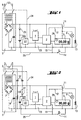
- the 1 consists of a weighing system 1, a digital one Signal processing unit 2, which is usually a microprocessor Main element contains, and a display 3 with backlighting (indicated by the light bulb 4).
- the balance is powered by a power pack 5, which consists of a transformer 6, a downstream rectifier 7 and there is a charging capacitor 8.
- the charging capacitor 8 can be a conventional one Circuit for voltage stabilization downstream (not shown).
- the Power supply (voltage supply) 5 is via a power switch 9 and over Plug contacts (mains connection) 10 connected to the AC voltage network.
- the scale has a switch 11 which, in the normal operating state (as drawn) the display 3 and the backlighting (light bulb) 4 (and possibly existing other age-sensitive, not shown in the figure Components) supplied with voltage.
- the Switch 11 via line 12 from digital signal processing electronics 2 switched and instead of the display 3 and the backlight 4, etc. is a Replacement consumer 13 connected to the supply voltage, the approximately generates as much heat as the switched off consumers, but none Aging shows. This keeps the thermal in standby mode Maintain balance within the balance.
- the operator of the scale initiates the switchover from the normal operating state to the standby operating state and vice versa by pressing the button 14 which e.g. is labeled with "On / Off" and that via the connecting line 15 with the digital Signal processing unit 2 is connected.
- the power switch 9 remains in both Normal operating state as well as closed in the standby operating state. -
- the Parts of the scale described so far and their function are generally known and therefore only briefly explained above.
- the scales according to the invention now additionally have a separate one Power supply in the form of a rechargeable energy store 20 which in Fig. 1 is drawn as a rechargeable battery, but also a capacitor high capacity.
- the energy store 20 is a Charging circuit 21 (shown in Fig. 1 for simplicity as a diode) both in Normal operating state as well as in standby operating state continuously charged or kept charged.
- the separate energy store 20 supplies one Clock module 22 with tension. Under clock module is both a Understood the block that has stored the time internally and this permanently updated, as well as a building block that a predetermined like a stopwatch Can count down to zero.
- the clock module 22 can with the exchange digital signal processing unit 2 via line 23, for example, the digital signal processing unit 2 can have a "wake-up time” in save the clock module or a period of time after which the "Wake-up pulse” should be triggered.
- the clock module 22 transfers the line 24 a switch-off pulse on the power switch 9, so that the entire Electronics - with the exception of clock module 22 - no supply voltage receives more.
- This new operating state called sleep mode remains, until the specified time period has expired or until the specified time is reached and the clock module 22 gives a pulse on the line 24 and turns on the power switch 9 again.
- the digital Signal processing unit 2 again its supply voltage and begins to work.
- the digital signal processing unit 2 is advantageously so programmed that after switching on the supply voltage in the Standby state goes.
- the power switch 9 is in accordance with that just described How a bistable switch works by a current / voltage pulse is brought into its other switching state and this switching state maintains without energy supply.
- the capacity of the energy store 20 is advantageously dimensioned so that that the clock module 22 can be operated for about 24 hours without one Reloading is required. This is with all scales every day be used at least once, the functionality of the clock module 22nd ensured until the next day.
- the operator of the scale can, for example, set the desired switch-on time in one Specify menu firmly.
- the operator programs with the same working hours every day a time that is 1 ... 2 hours before the start of work. To this The time then switches from the sleep mode described above to Standby operating state around and within the 1 ... 2 hours that is the case thermal equilibrium within the balance.
- the scale can be closed Start of work can be switched to normal operating status and is immediately available with their full accuracy.
- the digital signal processing unit 2 instead of specifying the switching time via the menu, it is also possible that in the digital signal processing unit a detector is present, the resting and Recognizes the working phases of the scale and saves their chronological sequence. From this stored data, future resting and Working phases are extrapolated and the digital signal processing unit 2 then sets the time for switching from sleep mode to standby mode 1 ... 2 hours before the extrapolated start of work. - On this way is an automatic adjustment to gradually changing Working hours possible.
- the charging circuit 21 for the separate energy store 20 is expedient dimensioned so that the energy storage is full again after approx. 2 hours is charged.
- the lead time of 1 ... 2 hours to reach the thermal Balance within the balance is then sufficient together with a minimum Time out in the normal operating state in order to fully charge the energy store 20 ensure.
- the digital reacts No signal processing unit 2 when the button 14 is pressed; around the scales switch from sleep mode back to normal operating mode by hand can, the button 14 is also via line 25 with the clock module 22nd connected. Pressing the button 14 during sleep mode causes thereby giving the clock module 22 a pulse on line 24 and the This will switch the balance to the standby mode.
- the missing thermal equilibrium within the balance is expedient e.g. by the blinking of the already mentioned clock symbol 26 in the display 3 of the Operator signals. After reaching thermal equilibrium - So after about 1 hour - this warning disappears. -
- the setting of the thermal equilibrium can advantageously be accelerated by that in the first period in addition to the replacement consumer 13 more Substitute consumers are switched on, or that both the substitute consumers 13 and the display 3 and the backlight 4 can be switched on.
- Switching to sleep mode by long pressing the button 14 can also serve to set the switch-on time: as long as the button 14 is held down, a time display appears in display 3 - for example starting with the current time - which is gradually introduced. At the When the desired reclosing time is reached, the operator releases button 14 and this time is saved as the switch-on time. - The same applies analogously for storing a period of time before switching on again.
- the watch module 22 advantageously also includes one Voltage monitoring circuit: This monitors the in sleep mode Voltage of the energy store 20 and emits a pulse on the line 24, if the voltage of the energy store 20 is below a predetermined limit sinks. As a result, the power switch 9 is switched on and the energy store 20 recharged. After a predetermined time - the charging time for the Energy storage 20 - the clock module 22 gives another impulse to the Line 24 and thereby turns off the power switch 9, if meanwhile the set restart time has not yet been reached.
- the clock module 22 contains one Radio clock receiver so that the internal time is always exact and the Summer / winter time changeover takes place automatically.
- the digital signal processing unit 2 contains a microprocessor, whose power consumption is sufficiently low can of course Clock module 22 be part of this microprocessor and the whole Microprocessor kept in a standby state during sleep mode become. Nevertheless, there is a reduction in the sleep mode Energy consumption compared to the standby mode, since the others electronic components of the digital signal processing unit 2 and Weigh sensor 1, the replacement consumer 13 and the power supply 5 no energy take up.
- FIG. 2 The block diagram of a second embodiment of the scale is shown in FIG. 2.
- Components 1 ... 15 and 22 ... 26 are with the corresponding components from Fig. 1 are identical and are therefore not explained again.
- Fig. 2nd a rectifier circuit 31 with a separate charging capacitor 30 provided that the two capacitors 32 directly to the two poles of the Mains connection 10 is connected.
- the two capacitors 32 ensure that the ground potential of the circuit is separated from the power supply potential.
- a voltage stabilization circuit behind the charging capacitor is possible if the clock module 22 requires this, in FIG. 2 for the sake of clarity however not shown.
- This primitive circuit without a transformer does not have a good one Efficiency due to the very low power consumption of the clock module 22 of less than 1 mA, the losses of this circuit are still less than that Losses of the power supply 5, which is for a significantly higher nominal power is dimensioned.
- the one required briefly for switching the power switch 9 Higher current is generated by the storage capacity of the charging capacitor 30 upset. - Otherwise, the operation of this circuit is identical to that already described operation of the circuit of FIG. 1.
- the Power consumption of this circuit is not quite zero in sleep mode, but with appropriate technology for the clock module 22, however, very low and significantly lower than in standby mode.
Landscapes
- Business, Economics & Management (AREA)
- Emergency Management (AREA)
- Engineering & Computer Science (AREA)
- Power Engineering (AREA)
- Physics & Mathematics (AREA)
- General Physics & Mathematics (AREA)
- Electric Clocks (AREA)
Abstract
Description
- Fig. 1
- ein Blockschaltbild der Waage in einer ersten Ausgestaltung und
- Fig. 2
- ein Blockschaltbild der Waage in einer zweiten Ausgestaltung.
Claims (12)
- Elektronische Waage, mit einer netzgespeisten Spannungsversorgung (5) bestehend aus einem Transformator (6) und einem nachgeschalteten Gleichrichter (7) mit Ladekondensator (8), mit einem Netzschalter (9) zwischen dem Transformator (6) und dem Netzanschluß (10) und mit mindestens zwei Betriebszuständen, wobei im Normalbetriebszustand alle elektronischen Bauelemente mit Spannung versorgt werden und im Standby-Betriebszustand die wesentlichen wärmeerzeugenden Bauelemente eingeschaltet sind, während alterungsempfindliche Bauelemente und die Anzeige (3) ausgeschaltet sind, dadurch gekennzeichnet, daß der Netzschalter (9) ein elektrisch betätigbarer Schalter ist, daß eine separate, von der netzgespeisten Spannungsversorgung (5) unabhängige Spannungsversorgung (20, 30) vorhanden ist, die zumindest einen Uhrenbaustein (22) mit Spannung versorgt, daß neben dem Normalbetriebszustand und dem Standby-Zustand ein weiterer Betriebszustand (Sleep-Mode) vorgesehen ist, bei dem der Netzschalter (9) geöffnet ist, und daß nach Ablauf einer vorgegebenen Zeit oder zu einer vorgegebenen Uhrzeit der Uhrenbaustein (22) den weiteren Betriebszustand selbsttätig beendet und in den Normalbetriebszustand oder den Standby-Betriebszustand umschaltet.
- Elektronische Waage nach Anspruch 1, dadurch gekennzeichnet, daß die separate Spannungsversorgung ein aufladbarer Energiespeicher (20) ist.
- Elektronische Waage nach Anspruch 2, dadurch gekennzeichnet, daß der aufladbare Energiespeicher (20) ein Kondensator hoher Kapazität ist.
- Elektronische Waage nach Anspruch 2, dadurch gekennzeichnet, daß der aufladbare Energiespeicher (20) eine aufladbare Batterie ist.
- Elektronische Waage nach einem der Ansprüche 2 bis 4, dadurch gekennzeichnet, daß der aufladbare Energiespeicher (20) sowohl während des Normalbetriebszustandes als auch während des Standby-Betriebszustandes von der netzgespeisten Spannungsversorgung (5) aufgeladen wird.
- Elektronische Waage nach einem der Ansprüche 2 bis 5, dadurch gekennzeichnet, daß vom separaten Energiespeicher (20) zusätzlich eine Spannungsüberwachungsschaltung versorgt wird, die den Ladezustand des aufladbaren Energiespeichers (20) überwacht und daß der weitere Betriebszustand zumindest solange unterbrochen wird, bis der aufladbare Energiespeicher (20) wieder genügend geladen ist.
- Elektronische Waage nach Anspruch 1, dadurch gekennzeichnet, daß die separate Spannungsversorgung aus einer Gleichrichterschaltung (31) mit Ladekondensator (30) besteht, die über zwei Kondensatoren (32) an die beiden Pole des Netzanschlusses (10) angeschlossen ist.
- Elektronische Waage nach einem der Ansprüche 1 bis 7, dadurch gekennzeichnet, daß der Netzschalter (9) ein bistabiler Schalter ist.
- Elektronische Waage nach einem der Ansprüche 1 bis 8, dadurch gekennzeichnet, daß der Uhrenbaustein (22) einen Funkuhr-Empfänger enthält.
- Elektronische Waage nach einem der Ansprüche 1 bis 9, dadurch gekennzeichnet, daß der Uhrenbaustein (22) Teil eines Mikroprozessors ist.
- Elektronische Waage nach einem der Ansprüche 1 bis 10, dadurch gekennzeichnet, daß die Uhrzeit zur selbsttätigen Beendigung des weiteren Betriebszustandes per Menü vorgegeben werden kann.
- Elektronische Waage nach einem der Ansprüche 1 bis 11, dadurch gekennzeichnet, daß innerhalb einer digitalen Signalverarbeitungseinheit (2) ein Detektor vorhanden ist, der Ruhephasen der Waage erkennt, daß Speichermittel vorhanden sind, die die Zeitdauer der Ruhephasen und der Arbeitsphasen speichern, daß Rechenprogramme vorhanden sind, die aus den gespeicherten Ruhe- und Arbeitsphasen die zukünftigen Ruhe- und Arbeitsphasen extrapolieren und daß vor Beginn einer zu erwartenden Arbeitsphase der weitere Betriebszustand selbsttätig beendet wird und der Standby-Betriebszustand eingeschaltet wird.
Applications Claiming Priority (2)
| Application Number | Priority Date | Filing Date | Title |
|---|---|---|---|
| DE19853892A DE19853892C1 (de) | 1998-11-23 | 1998-11-23 | Elektronische Waage mit Standby-Betriebszustand |
| DE19853892 | 1998-11-23 |
Publications (2)
| Publication Number | Publication Date |
|---|---|
| EP1004860A1 true EP1004860A1 (de) | 2000-05-31 |
| EP1004860B1 EP1004860B1 (de) | 2006-07-26 |
Family
ID=7888655
Family Applications (1)
| Application Number | Title | Priority Date | Filing Date |
|---|---|---|---|
| EP99122987A Expired - Lifetime EP1004860B1 (de) | 1998-11-23 | 1999-11-19 | Elektronische Waage mit Standby-Betriebszustand |
Country Status (5)
| Country | Link |
|---|---|
| US (1) | US6373237B1 (de) |
| EP (1) | EP1004860B1 (de) |
| JP (1) | JP3193362B2 (de) |
| CN (1) | CN1116591C (de) |
| DE (2) | DE19853892C1 (de) |
Families Citing this family (25)
| Publication number | Priority date | Publication date | Assignee | Title |
|---|---|---|---|---|
| US20040139360A1 (en) * | 2003-01-15 | 2004-07-15 | Bliley Paul D. | Off mode for device |
| JP2007155681A (ja) * | 2005-12-08 | 2007-06-21 | Shimadzu Corp | 電子天びん |
| DE102005058851B3 (de) * | 2005-12-09 | 2007-04-19 | Sartorius Ag | Elektronische Waage |
| DE102008011279A1 (de) * | 2007-12-03 | 2009-06-10 | Fujitsu Siemens Computers Gmbh | Elektrisches Gerät |
| JP5515161B2 (ja) | 2007-12-27 | 2014-06-11 | 株式会社タニタ | 重量計 |
| US7547851B1 (en) * | 2008-06-02 | 2009-06-16 | Sunbeam Products, Inc. | Advanced buttonless scale |
| JP5234938B2 (ja) * | 2008-07-31 | 2013-07-10 | 株式会社イシダ | 重量検査装置 |
| ES2417304T3 (es) * | 2008-11-25 | 2013-08-07 | Arçelik Anonim Sirketi | Dispositivo de suministro de energía de reserva |
| US20100258356A1 (en) * | 2008-11-27 | 2010-10-14 | Aparna Thirumalai Anandampillai | Refrigerator for obese persons |
| US8823518B2 (en) * | 2008-12-08 | 2014-09-02 | Motorola Solutions, Inc. | Method of sensor cluster processing for a communication device |
| US8624430B2 (en) * | 2009-11-19 | 2014-01-07 | General Electric Company | Standby power reduction |
| JP5525294B2 (ja) * | 2010-03-11 | 2014-06-18 | 株式会社イシダ | 電子秤 |
| US8287078B2 (en) | 2010-07-23 | 2012-10-16 | Xerox Corporation | Inkjet printing system having environmentally responsive thermal control mode |
| WO2013001335A2 (en) * | 2011-06-27 | 2013-01-03 | Hap Nguyen | System and method of eliminating wasted energy known as vampire electricity or phantom load loss |
| GB2492603A (en) * | 2011-07-08 | 2013-01-09 | Nicola Caroline Ternan Harris | Electrical time switch |
| DE102011111467A1 (de) * | 2011-08-23 | 2013-02-28 | Minebea Co., Ltd. | Überwachungseinheit für Transportgüter |
| CN102564552B (zh) * | 2011-12-20 | 2015-04-22 | 福建新大陆电脑股份有限公司 | 电子秤电源管理方法及装置 |
| CN102564556B (zh) * | 2012-01-07 | 2014-07-09 | 中山佳维电子有限公司 | 一种智能省电电子秤的控制方法及控制系统 |
| JP2014006057A (ja) * | 2012-06-21 | 2014-01-16 | Tanita Corp | 生体測定装置 |
| US20140265566A1 (en) * | 2013-03-16 | 2014-09-18 | Hap Nguyen | System and Method of Eliminating Wasted Energy Known as Vampire Electricity or Phantom Load Loss |
| DE102014019435A1 (de) | 2014-12-22 | 2016-06-23 | Audi Ag | Verfahren zum Betreiben eines Infotainmentsystems, Infotainmentsystem und Fahrzeug |
| CN109282887A (zh) * | 2017-07-21 | 2019-01-29 | 长沙恒凯电子科技有限公司 | 电子秤 |
| CN110908719A (zh) * | 2018-09-17 | 2020-03-24 | 梅特勒-托利多(常州)测量技术有限公司 | 一种动态功耗管理和唤醒的方法及其应用系统 |
| US11017641B2 (en) * | 2018-12-21 | 2021-05-25 | Sbot Technologies Inc. | Visual recognition and sensor fusion weight detection system and method |
| CN111707341A (zh) * | 2020-06-24 | 2020-09-25 | 北京恒通安泰科技有限公司 | 用于轨道衡的数据采集装置、数据采集方法及轨道衡 |
Citations (2)
| Publication number | Priority date | Publication date | Assignee | Title |
|---|---|---|---|---|
| DE2922848A1 (de) * | 1979-06-06 | 1980-12-18 | Sartorius Gmbh | Digital anzeigende waage |
| WO1998048498A2 (en) * | 1997-04-23 | 1998-10-29 | Wexl | Energy management method and apparatus |
Family Cites Families (10)
| Publication number | Priority date | Publication date | Assignee | Title |
|---|---|---|---|---|
| CH601779A5 (de) * | 1976-06-01 | 1978-07-14 | Mettler Instrumente Ag | |
| CH612503A5 (de) * | 1977-05-13 | 1979-07-31 | Mettler Instrumente Ag | |
| US4364442A (en) * | 1981-02-20 | 1982-12-21 | L. & D. Sales Corporation | Digital scale |
| US4763739A (en) * | 1987-11-09 | 1988-08-16 | Hobart Corporation | Energy efficient scale |
| US5254992A (en) * | 1991-10-31 | 1993-10-19 | Fairbanks Inc. | Low power electronic measuring system |
| US5207284A (en) * | 1991-11-22 | 1993-05-04 | Fairbanks, Inc. | Mechanical scale conversion system |
| US5349516A (en) * | 1992-09-17 | 1994-09-20 | Rca Thomson Licensing Corporation | Switch mode power supply with reduced input current distortion |
| US5426579A (en) * | 1993-07-28 | 1995-06-20 | Best Power Technology, Incorporated | Method and apparatus for stabilizing AC power supply systems connected to power factor correcting loads |
| US5563781A (en) * | 1993-11-24 | 1996-10-08 | Integrated Technology Corporation | Dual-mode power converter |
| US5729120A (en) * | 1996-12-30 | 1998-03-17 | General Signal Corporation | Dynamic voltage regulation stabilization for AC power supply systems |
-
1998
- 1998-11-23 DE DE19853892A patent/DE19853892C1/de not_active Expired - Fee Related
-
1999
- 1999-11-13 DE DE29919934U patent/DE29919934U1/de not_active Expired - Lifetime
- 1999-11-16 US US09/440,941 patent/US6373237B1/en not_active Expired - Fee Related
- 1999-11-19 EP EP99122987A patent/EP1004860B1/de not_active Expired - Lifetime
- 1999-11-22 CN CN99124483A patent/CN1116591C/zh not_active Expired - Fee Related
- 1999-11-22 JP JP33181499A patent/JP3193362B2/ja not_active Expired - Fee Related
Patent Citations (2)
| Publication number | Priority date | Publication date | Assignee | Title |
|---|---|---|---|---|
| DE2922848A1 (de) * | 1979-06-06 | 1980-12-18 | Sartorius Gmbh | Digital anzeigende waage |
| WO1998048498A2 (en) * | 1997-04-23 | 1998-10-29 | Wexl | Energy management method and apparatus |
Also Published As
| Publication number | Publication date |
|---|---|
| US6373237B1 (en) | 2002-04-16 |
| EP1004860B1 (de) | 2006-07-26 |
| JP3193362B2 (ja) | 2001-07-30 |
| DE19853892C1 (de) | 2000-05-11 |
| JP2000258236A (ja) | 2000-09-22 |
| CN1116591C (zh) | 2003-07-30 |
| DE29919934U1 (de) | 2000-04-06 |
| CN1254830A (zh) | 2000-05-31 |
Similar Documents
| Publication | Publication Date | Title |
|---|---|---|
| DE19853892C1 (de) | Elektronische Waage mit Standby-Betriebszustand | |
| EP0319941A1 (de) | Verfahren für die Stromversorgung von mit Solarzellen betriebenen elektronischen Schaltungen und Anordnung zur Durchführung des Verfahrens | |
| DE3524290C2 (de) | ||
| DE3003452C2 (de) | ||
| DE3003453A1 (de) | Schaltungsanordnung zur steuerung der ausgangsleistung eines widerstandsheizelementes | |
| DE102017211900B4 (de) | Leistungsschalter und Verfahren | |
| DE202011050972U1 (de) | Batterieladesystem mit mehreren Lademodi | |
| EP0115625B1 (de) | Verfahren und Anordnung zur optischen und/oder akustischen Anzeige des Ladezustandes einer Batterie oder eines Akkumulators | |
| EP0759655A2 (de) | Verfahren und Vorrichtung zum Reduzieren des Energieverbrauchs bei einem durch einen Spannungswandler versorgten Elektrogerät | |
| DE4426509C2 (de) | Einrichtung zur Anzeige der elektrischen Verbrauchsdaten eines Verbrauchers | |
| DE69917479T2 (de) | Ansteuerungsschema und elektronischer schaltkreis für ein elektooptisches lcd-schaltelement | |
| DE2442394B2 (de) | Vollelektronische uhr | |
| EP0285838B1 (de) | Autonome Funkuhr | |
| CN209642549U (zh) | 一种大电流直流电源开关电路 | |
| DE19732299A1 (de) | Netzspannungsversorgungseinrichtung | |
| DE10063689B4 (de) | Hausgerät mit einer Uhr | |
| EP0603815B1 (de) | Netzunabhängige elektronische Uhr | |
| CH687423A5 (de) | Multifunktionszaehler. | |
| CN2294488Y (zh) | 家庭自动化控制装置 | |
| CN204376370U (zh) | 一种磁保持自复式过欠压保护器 | |
| JPS6110233Y2 (de) | ||
| DE4305242A1 (de) | Elektrische Quarzweckeruhr | |
| DE2939779A1 (de) | Zeitschaltuhr zum ein- und ausschalten einer netzspannung | |
| DE2706916B2 (de) | Uhren-Radio-Recorder | |
| JPS62203089A (ja) | 計時装置 |
Legal Events
| Date | Code | Title | Description |
|---|---|---|---|
| PUAI | Public reference made under article 153(3) epc to a published international application that has entered the european phase |
Free format text: ORIGINAL CODE: 0009012 |
|
| AK | Designated contracting states |
Kind code of ref document: A1 Designated state(s): CH FR GB LI |
|
| AX | Request for extension of the european patent |
Free format text: AL;LT;LV;MK;RO;SI |
|
| 17P | Request for examination filed |
Effective date: 20000525 |
|
| AKX | Designation fees paid |
Free format text: CH FR GB LI |
|
| REG | Reference to a national code |
Ref country code: DE Ref legal event code: 8566 |
|
| 17Q | First examination report despatched |
Effective date: 20050503 |
|
| GRAP | Despatch of communication of intention to grant a patent |
Free format text: ORIGINAL CODE: EPIDOSNIGR1 |
|
| GRAS | Grant fee paid |
Free format text: ORIGINAL CODE: EPIDOSNIGR3 |
|
| GRAA | (expected) grant |
Free format text: ORIGINAL CODE: 0009210 |
|
| AK | Designated contracting states |
Kind code of ref document: B1 Designated state(s): CH FR GB LI |
|
| PG25 | Lapsed in a contracting state [announced via postgrant information from national office to epo] |
Ref country code: GB Free format text: LAPSE BECAUSE OF FAILURE TO SUBMIT A TRANSLATION OF THE DESCRIPTION OR TO PAY THE FEE WITHIN THE PRESCRIBED TIME-LIMIT Effective date: 20060726 |
|
| REG | Reference to a national code |
Ref country code: GB Ref legal event code: FG4D Free format text: NOT ENGLISH |
|
| REG | Reference to a national code |
Ref country code: CH Ref legal event code: NV Representative=s name: A. BRAUN, BRAUN, HERITIER, ESCHMANN AG PATENTANWAE Ref country code: CH Ref legal event code: EP |
|
| GBV | Gb: ep patent (uk) treated as always having been void in accordance with gb section 77(7)/1977 [no translation filed] |
Effective date: 20060726 |
|
| EN | Fr: translation not filed | ||
| PLBE | No opposition filed within time limit |
Free format text: ORIGINAL CODE: 0009261 |
|
| STAA | Information on the status of an ep patent application or granted ep patent |
Free format text: STATUS: NO OPPOSITION FILED WITHIN TIME LIMIT |
|
| 26N | No opposition filed |
Effective date: 20070427 |
|
| PG25 | Lapsed in a contracting state [announced via postgrant information from national office to epo] |
Ref country code: FR Free format text: LAPSE BECAUSE OF FAILURE TO SUBMIT A TRANSLATION OF THE DESCRIPTION OR TO PAY THE FEE WITHIN THE PRESCRIBED TIME-LIMIT Effective date: 20070511 |
|
| REG | Reference to a national code |
Ref country code: CH Ref legal event code: PFA Owner name: SARTORIUS AG Free format text: SARTORIUS AG#WEENDER LANDSTRASSE 94-108#37075 GOETTINGEN (DE) -TRANSFER TO- SARTORIUS AG#WEENDER LANDSTRASSE 94-108#37075 GOETTINGEN (DE) |
|
| PG25 | Lapsed in a contracting state [announced via postgrant information from national office to epo] |
Ref country code: FR Free format text: LAPSE BECAUSE OF FAILURE TO SUBMIT A TRANSLATION OF THE DESCRIPTION OR TO PAY THE FEE WITHIN THE PRESCRIBED TIME-LIMIT Effective date: 20060726 |
|
| REG | Reference to a national code |
Ref country code: CH Ref legal event code: PUE Owner name: SARTORIUS WEIGHING TECHNOLOGY GMBH Free format text: SARTORIUS AG#WEENDER LANDSTRASSE 94-108#37075 GOETTINGEN (DE) -TRANSFER TO- SARTORIUS WEIGHING TECHNOLOGY GMBH#WEENDER LANDSTRASSE 94-108#37075 GOETTINGEN (DE) |
|
| PGFP | Annual fee paid to national office [announced via postgrant information from national office to epo] |
Ref country code: CH Payment date: 20121113 Year of fee payment: 14 |
|
| REG | Reference to a national code |
Ref country code: CH Ref legal event code: PL |
|
| PG25 | Lapsed in a contracting state [announced via postgrant information from national office to epo] |
Ref country code: CH Free format text: LAPSE BECAUSE OF NON-PAYMENT OF DUE FEES Effective date: 20131130 Ref country code: LI Free format text: LAPSE BECAUSE OF NON-PAYMENT OF DUE FEES Effective date: 20131130 |