EP1004721B1 - Verteilvorrichtung - Google Patents
Verteilvorrichtung Download PDFInfo
- Publication number
- EP1004721B1 EP1004721B1 EP98811150A EP98811150A EP1004721B1 EP 1004721 B1 EP1004721 B1 EP 1004721B1 EP 98811150 A EP98811150 A EP 98811150A EP 98811150 A EP98811150 A EP 98811150A EP 1004721 B1 EP1004721 B1 EP 1004721B1
- Authority
- EP
- European Patent Office
- Prior art keywords
- support
- pipe
- tube
- carrying pipe
- bend
- Prior art date
- Legal status (The legal status is an assumption and is not a legal conclusion. Google has not performed a legal analysis and makes no representation as to the accuracy of the status listed.)
- Expired - Lifetime
Links
- 239000000463 material Substances 0.000 claims abstract description 15
- 239000000725 suspension Substances 0.000 claims description 7
- 238000005728 strengthening Methods 0.000 claims 3
- 239000013590 bulk material Substances 0.000 claims 1
- 238000007599 discharging Methods 0.000 claims 1
- 230000008878 coupling Effects 0.000 description 7
- 238000010168 coupling process Methods 0.000 description 7
- 238000005859 coupling reaction Methods 0.000 description 7
- 230000002787 reinforcement Effects 0.000 description 4
- XEEYBQQBJWHFJM-UHFFFAOYSA-N Iron Chemical compound [Fe] XEEYBQQBJWHFJM-UHFFFAOYSA-N 0.000 description 2
- 230000005540 biological transmission Effects 0.000 description 2
- 238000010276 construction Methods 0.000 description 2
- 238000005086 pumping Methods 0.000 description 2
- 230000003014 reinforcing effect Effects 0.000 description 2
- 229920001875 Ebonite Polymers 0.000 description 1
- 229910000831 Steel Inorganic materials 0.000 description 1
- 229910052782 aluminium Inorganic materials 0.000 description 1
- XAGFODPZIPBFFR-UHFFFAOYSA-N aluminium Chemical compound [Al] XAGFODPZIPBFFR-UHFFFAOYSA-N 0.000 description 1
- 238000006073 displacement reaction Methods 0.000 description 1
- 239000003337 fertilizer Substances 0.000 description 1
- 230000001771 impaired effect Effects 0.000 description 1
- 229910052742 iron Inorganic materials 0.000 description 1
- 239000007788 liquid Substances 0.000 description 1
- 238000003754 machining Methods 0.000 description 1
- 229910052751 metal Inorganic materials 0.000 description 1
- 239000002184 metal Substances 0.000 description 1
- 230000000284 resting effect Effects 0.000 description 1
- 230000000630 rising effect Effects 0.000 description 1
- 239000004576 sand Substances 0.000 description 1
- 239000010959 steel Substances 0.000 description 1
- 238000003466 welding Methods 0.000 description 1
Images



Classifications
-
- E—FIXED CONSTRUCTIONS
- E04—BUILDING
- E04G—SCAFFOLDING; FORMS; SHUTTERING; BUILDING IMPLEMENTS OR AIDS, OR THEIR USE; HANDLING BUILDING MATERIALS ON THE SITE; REPAIRING, BREAKING-UP OR OTHER WORK ON EXISTING BUILDINGS
- E04G21/00—Preparing, conveying, or working-up building materials or building elements in situ; Other devices or measures for constructional work
- E04G21/02—Conveying or working-up concrete or similar masses able to be heaped or cast
- E04G21/04—Devices for both conveying and distributing
-
- E—FIXED CONSTRUCTIONS
- E04—BUILDING
- E04G—SCAFFOLDING; FORMS; SHUTTERING; BUILDING IMPLEMENTS OR AIDS, OR THEIR USE; HANDLING BUILDING MATERIALS ON THE SITE; REPAIRING, BREAKING-UP OR OTHER WORK ON EXISTING BUILDINGS
- E04G21/00—Preparing, conveying, or working-up building materials or building elements in situ; Other devices or measures for constructional work
- E04G21/02—Conveying or working-up concrete or similar masses able to be heaped or cast
- E04G21/04—Devices for both conveying and distributing
- E04G21/0418—Devices for both conveying and distributing with distribution hose
- E04G21/0427—Devices for both conveying and distributing with distribution hose on a static support, e.g. crane
Definitions
- the present invention relates to a device according to the preamble of the claim 1.
- a concrete distributor which is arranged on a chassis and each has a pipe for feeding and distributing the concrete.
- the telescopic trained distribution pipe can only be pivoted in a small area, which is why to enlarge a displacement of the chassis is required for the radius of action of the distributor.
- From DE-A-2 711 787 is a two-armed concrete round distributor for distributing concrete mass known, which consists essentially of a connecting tube attached to a table exists, to which a feed pipe and a carrier pipe are connected.
- the carrier tube is on attached to a frame that stands on the table with rollers and is rotatable on it. It is connected to the connecting pipe so that it is 360 over the surface to be concreted Degree is rotatable.
- a distribution tube is connected as a second arm, that it is rotatable in a plane running parallel to the surface to be machined is. So the concrete can be placed on any point of a circular surface, whose radius corresponds approximately to the total length of the carrier pipe and distribution pipe.
- the present invention is therefore based on the object of the known distributor improve and create a device for distributing loose material that is so light and is so handy that it can be easily set up, operated and safely by one person can also be transported without special aids. This is done with a device of type mentioned by the specified in the characterizing part of claim 1 Measures achieved. Advantageous embodiments of the invention and a special one Use of the device are specified in further claims.
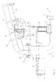
- the device consists of a feed pipe 13, via which the distributing material, e.g. Concrete, brought in by a pump.
- the one or multi-part feed pipe 13 running approximately parallel to surface 25 is by means of a known pipe-shell coupling connected to a connecting pipe bend 14. It is on editions 24, which in turn are arranged on reinforcing elements 6 of the surface 25 to be provided with concrete are.
- the connecting pipe bend 14 is fastened to a table 11 by means 32, 33. On his at the other end on the top of the table 11 is a support tube 10 which can be rotated through 360 degrees connected, which is slightly rising.
- a rotatable connecting element between The carrier tube 10 and the connecting tube bend 14 are particularly suitable for a known one so-called rotary shell coupling 8.
- Shell coupling 7 and further shell couplings 37 for connecting individual parts of the Feed tube 13 is not rotatable, they only serve to rigidly connect pipe parts.
- a distribution tube 21 is also rotatably connected.
- the distribution pipe 21 is used to discharge the concrete. It is fastened to a suspension 12 and connected to the carrier tube 10 via a rotary shell coupling 38. In this way, it can be rotated arbitrarily by 360 degrees in a plane running at least approximately parallel to surface 25.
- the two ends of the suspension 12 are connected with plug-like connecting elements to the carrier tube 10 or to the distribution tube 21.
- the inclination of the support tube 10 is selected so that the distribution tube 21 assumes a suitable working height.
- a reinforcement 26 is attached on the underside of the support tube 10, for example a U-shaped profile, which receives the support tube 10 and is fixed to it by means of clips 28.
- a support 15 is attached to the support pipe 10 and the reinforcement 26 on both sides. Details of this are shown in FIGS. 2 and 5.
- the support 15 consists of a threaded rod 3 which engages in a screw nut 30 - for example a hexagon nut - which is firmly connected to a holder 2.
- the holder 2 has two supports 9a, 9b, between which a roller 1 resting on the table 11 is rotatably mounted.
- the roller 1 can be in one piece or, to improve the running properties, consist of several rollers, which are preferably provided with ball bearings in a known manner. Steel or hard rubber is suitable as the roll material.
- connection web 31 slipped over the threaded rod 3, e.g. a flat iron, which at its other end in the same way over the threaded rod of the other support is put up.
- the connecting web 31 serves to stabilize the supports 15 with one another.
- screw nut 29 applied, which is freely rotatable.
- the threaded rod 3 is at its top End rotatably connected to the support tube 10 or to the support 26 via a hinge pin 4
- the hinge pin 4 fastened to the carrier tube 10 or to the carrier 26 engages in a Bore 35 at the upper end of the threaded rod 3.
- the holder 2 By turning the screw nut 30, the holder 2 is moved along the threaded rod 3 and brought into a desired position. When this situation is reached, it can be done Tightening the movable screw nut 29 can be fixed against the connecting web 31.
- the inclination (angle ⁇ in Fig. 2) of the support tube 10 can be set so that the Welding rings 27a, 27b on the carrier tube 10 and on the connecting tube bend 14 of the shell coupling 8 in each working position of the two pipes a certain minimum possible parallel Keep a distance from each other. This is especially for a flawless at all times Rotation function and play-free power transmission between support tube 10 and connecting tube bend 14 with a secure seal between the two pipes 10, 14 important.
- the angle between the axis of the rollers 1 and the longitudinal direction of the support tube 10, i.e. the path of the rollers 1 on the table 11, so chosen and set, that they move on an ideal circular path, which gives optimal turning characteristics for the support tube 10 results.
- Locking screws fastened to the reinforcement 26 and directed against the wall 36a of the stop 36 5a, 5b are used for fine adjustment of the angle ⁇ between the support 15 and the Carrier tube 10 and for fixing the set angle ⁇ .
- the angle ⁇ between the support 15 and the carrier 10 smaller.
- the angle ⁇ can be reversed Increase the rotation of the locking screws 5a, 5b.
- the device With the supports 15 on the support tube 10, the device is provided in any position of the support tube 10 and / or the distribution pipe 21 (FIG. 4) together with the feed pipe 13 and with that below still described support of the table 11 a stable position without a counterweight necessary is.
- a tried and tested version of the device with a support tube 10 from approx. 2.8 meters in length and a distribution pipe of approx. 3.5 meters in length with a pipe diameter of 100mm maintains its stability in every working position even during operation as a concrete distributor and cannot tip over.
- the device allows the stable Machining anywhere within a circular area with a radius defined by the Length of support tube 10 and distribution tube 21 is determined. It is only by the weight, i.e. without using a counterweight, in any working position within this area ensures constant stability of the device.
- a single support 15 may suffice, either immediately under the support tube 10 or under the reinforcement 26 or also attached laterally is.
- tests have shown that by using two supports 15 an optimal The easiest way to set the turning properties of the device with play-free power transmission and best achieved.
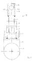
- the table 11 is apparent from FIGS. 3 and 4 height-adjustable legs and length-adjustable cross struts. So are on of the side 39 of the table 11 which is transverse to the feed pipe 13, two legs 16, 17 are provided which are either attached directly to the table 11 or, as in FIG. 4, with suspensions 22.23 the table 11 are connected. The suspensions 22, 23 slidably engage in a counterpart under the table 11, so that the distance of the legs 16, 17 from the table 11 telescopically as desired can be adjusted.
- Page 40 of the table 11 are telescopically extendable cross struts in the same way 18a and 18b are provided, at the ends of which legs 19 and 20 are attached.
- the cross braces run perpendicular to the direction of the feed pipe 13 in the example shown. However, this is not necessarily.
- the cross struts 18a, 18b can also be at a different angle to the direction of the feed pipe 13 are arranged. With a suitable construction, the Arrange the cross struts so that they can be adjusted to a suitable angle as required can be. Likewise, the suspensions 22, 23 can be at a different angle than in FIG. 4 shown attached.
- the device can be practically anywhere on a surface 25 put on and in a desired optimal position with absolute stability be brought in any work situation.
- the feed tube 13 also serves as a further cross strut and thus contributes significantly to the stability of the device in every working position.
- the module-like device can be set up relatively quickly without any special aids Disassemble small and handy individual parts, which is why they are assembled, disassembled and transported Usually one person is enough and only a small loading area on a transport vehicle is required.
- Such handy and relatively light parts form the table, for example 11 together with the connecting pipe bend 14, or the carrier pipe 10 together with the Prop 15, or the manifold 21 alone.
- These parts can be quickly and easily installed on site assemble and the device is ready for use within a very short time.
- a light metal such as e.g. Aluminum, be provided.
- the use of the device as a concrete round distributor described above is only one of many possible applications. Other uses, where material by pumping or conveyed by compressed air through a pipe system are conceivable. So the device for Distribution of gravel or sand and for spreading liquid or powdery materials, how fertilizers are used in agriculture etc.
Landscapes
- Engineering & Computer Science (AREA)
- Architecture (AREA)
- Mechanical Engineering (AREA)
- Civil Engineering (AREA)
- Structural Engineering (AREA)
- On-Site Construction Work That Accompanies The Preparation And Application Of Concrete (AREA)
- Physical Deposition Of Substances That Are Components Of Semiconductor Devices (AREA)
- Discharge Of Articles From Conveyors (AREA)
- Paper (AREA)
- Bending Of Plates, Rods, And Pipes (AREA)
Description
- Die durch das Gewicht der beim Betrieb mit Material gefüllten Trägerrohre und Verteilrohre auftretenden Kräfte werden in jeder Arbeitslage optimal auf den Tisch und damit auf die Standfläche der Vorrichtung übertragen.
- Das Zuführrohr trägt wesentlich zur Abstützung und damit zur notwendigen Standsicherheit der Vorrichtung in jeder Arbeitslage bei, so dass im Gegensatz zu der aus der DE-A-2 711 787 bekannten Vorrichtung keine zusätzlichen Gegengewichte mit den Trägerarmen erforderlich sind. Das Zuführrohr dient sowohl als Abstützung für die Vorrichtung als auch als Gegengewicht.
- Die erfindungsgemässe weitere Ausgestaltung und Anordnung der Stützen mit den Rollen erfordern sehr wenig Platz und gewährleisten, dass die auftretenden Kräfte in jeder Arbeitslage der Vorrichtung spielfrei übertragen werden, so dass die Drehbarkeit von Trägerrohr und Verteilrohr nicht beeinträchtigt wird und insbesondere beim Pumpen von Material keine pulsierenden Schwingungen auftreten können. Ferner kann auf den auf dem Tisch drehbaren Rahmen gemäss DE-A-2 711 787 verzichtet werden. Daraus ergibt sich eine kompakte und relativ leichte Vorrichtung, die ohne weiteres auf einem Kleintransporter mitgeführt werden kann. Zudem ist die Vorrichtung einfach und schnell mit wenigen Handgriffen und ohne besondere Hilfsmittel montier- und demontierbar.
- Fig. 1
- eine Seitenansicht der vollständigen erfindungsgemässen Vorrichtung
- Fig. 2
- einen vergrösserten Ausschnitt von Fig. 1
- Fig. 3a
- eine weitere Ansicht der Vorrichtung
- Fig. 3b
- einen vergrösserten Ausschnitt von Fig.3a
- Fig. 4
- eine Sicht von oben auf die Vorrichtung
- Fig. 5
- Einzelheiten einer Stütze der Vorrichtung
In der Nähe der Verbindungsstelle zwischen Verbindungsrohrbogen 14 und Trägerrohr 10 sind beidseitig am Trägerrohr 10 bzw. an der Verstärkung 26 je eine Stütze 15 angebracht. Einzelheiten hierzu sind aus Fig. 2 und 5 ersichtlich. Die Stütze 15 besteht aus einer Gewindestange 3. die in eine Schraubenmutter 30 - z.B. eine Sechskantmutter - eingreift, die fest mit einer Halterung 2 verbunden ist. Die Halterung 2 weist zwei Träger 9a,9b auf, zwischen denen eine auf dem Tisch 11 aufliegende Rolle 1 drehbar angebracht ist. Die Rolle 1 kann einteilig sein oder zur Verbesserung der Laufeigenschaften aus mehreren Rollen bestehen, die vorzugsweise in bekannter Art mit Kugellagern versehen sind. Als Rollenmaterial eignet sich Stahl oder Hartgummi.
Claims (10)
- Vorrichtung zum Verteilen von losem Material auf einer Fläche (25), mit einem Verbindungsrohrbogen (14), dessen eines Ende mit einem Zuführrohr (13) zur Zuführung des Materials und dessen anderes Ende mit einem um eine wenigstens annähernd senkrecht zur Fläche (25) stehenden Achse drehbaren Trägerrohr (10) verbunden ist, an das ein Verteilrohr (21) zum Ausstossen des Materials derart anschliessbar ist, dass es in einer wenigstens annähernd parallel zur Fläche (25) verlaufenden Ebene drehbar ist, wobei der Verbindungsrohrbogen (14) fest mit einem auf der Fläche (25) aufstellbaren Tisch (11) verbunden ist, und dass am Trägerrohr (10) eine Stütze (15) mit einer Rolle (1) angebracht ist, die auf dem Tisch (11) aufliegt und bei Drehung des Trägerrohres (10) auf dem Tisch (11) abrollt, dadurch gekennzeichnet, dass die beiden Endbereiche des Verbindungsrohrbogens (14) mit Mitteln (32, 33) am Tisch (11) befestigt sind und dass das Zuführrohr (13) auf der Fläche (25) auflegbar ist und so als Abstützung dient.
- Vorrichtung nach Anspruch 1, dadurch gekennzeichnet, dass die Stütze (15) gelenkig mit dem Trägerrohr (10) oder einer Verstärkung (26) verbunden ist.
- Vorrichtung nach Anspruch 2, dadurch gekennzeichnet, dass seitlich am Trägerrohr (10) oder an der Verstärkung (26) zwei Stützen (15) vorgesehen sind, die je über ein Gelenk (4) mit dem Trägerrohr (10) bzw. der Verstärkung (26) verbunden sind.
- Vorrichtung nach einem der Ansprüche 1 bis 3, dadurch gekennzeichnet, dass die Stütze (15) Mittel aufweist, um die Neigung des Trägerrohrs (10) einzustellen.
- Vorrichtung nach einem der Ansprüche 1 bis 4, dadurch gekennzeichnet, dass die Stütze (15) Mittel aufweist, um die Laufbahn der Rollen (1) einzustellen.
- Vorrichtung nach Anspruch 4 und/oder 5, dadurch gekennzeichnet, dass die Stütze (15) aus einer gelenkig mit dem Trägerrohr (10) verbundenen Gewindestange (3) besteht, die in ein Gewinde in einer die Rollen (1) tragenden Halterung (2) greift.
- Vorrichtung nach einem der Ansprüche 1 bis 6, dadurch gekennzeichnet, dass der Tisch (11) mit Beinen (16, 17, 19, 20) versehen ist, deren Länge einstellbar ist.
- Vorrichtung nach Anspruch 7, dadurch gekennzeichnet, dass die Beine (16, 17; 19, 20) mittels in der Länge veränderbaren Aufhängungen (22, 23) bzw. Querstreben (18a, 18b) am Tisch (11) angebracht sind.
- Vorrichtung nach Anspruch 8, dadurch gekennzeichnet, dass der Winkel der Aufhängungen (22, 23) bzw. Querstreben (18a, 18b) zu den Seiten des Tisches (11) veränderbar ist.
- Anwendung der Vorrichtung nach Anspruch 1 zum Verteilen von Beton.
Priority Applications (3)
| Application Number | Priority Date | Filing Date | Title |
|---|---|---|---|
| DE59800637T DE59800637D1 (de) | 1998-11-20 | 1998-11-20 | Verteilvorrichtung |
| AT98811150T ATE200551T1 (de) | 1998-11-20 | 1998-11-20 | Verteilvorrichtung |
| EP98811150A EP1004721B1 (de) | 1998-11-20 | 1998-11-20 | Verteilvorrichtung |
Applications Claiming Priority (1)
| Application Number | Priority Date | Filing Date | Title |
|---|---|---|---|
| EP98811150A EP1004721B1 (de) | 1998-11-20 | 1998-11-20 | Verteilvorrichtung |
Publications (2)
| Publication Number | Publication Date |
|---|---|
| EP1004721A1 EP1004721A1 (de) | 2000-05-31 |
| EP1004721B1 true EP1004721B1 (de) | 2001-04-11 |
Family
ID=8236446
Family Applications (1)
| Application Number | Title | Priority Date | Filing Date |
|---|---|---|---|
| EP98811150A Expired - Lifetime EP1004721B1 (de) | 1998-11-20 | 1998-11-20 | Verteilvorrichtung |
Country Status (3)
| Country | Link |
|---|---|
| EP (1) | EP1004721B1 (de) |
| AT (1) | ATE200551T1 (de) |
| DE (1) | DE59800637D1 (de) |
Family Cites Families (6)
| Publication number | Priority date | Publication date | Assignee | Title |
|---|---|---|---|---|
| US2331373A (en) * | 1940-11-22 | 1943-10-12 | Fisher & Ludlow Ltd | Liquid discharge appliance |
| DE1759404C3 (de) * | 1968-04-27 | 1974-03-28 | Friedrich Dipl.-Ing. 4680 Wanne-Eickel Schwing | Vorrichtung zum Verteilen von Beton |
| US3860175A (en) * | 1972-12-21 | 1975-01-14 | Forms Const | Mobile concrete distributing boom apparatus |
| SE392495B (sv) * | 1976-03-26 | 1977-03-28 | S O A Lindqvist | Anordning for fordelning av betongmassa |
| US4262696A (en) * | 1978-05-16 | 1981-04-21 | Rotec Industries, Inc. | Swivel arm concrete placer |
| DE4225716C2 (de) * | 1992-08-04 | 1999-07-08 | Michael Modjesch | Vorrichtung zum Auftragen von Mörtel |
-
1998
- 1998-11-20 DE DE59800637T patent/DE59800637D1/de not_active Expired - Fee Related
- 1998-11-20 EP EP98811150A patent/EP1004721B1/de not_active Expired - Lifetime
- 1998-11-20 AT AT98811150T patent/ATE200551T1/de not_active IP Right Cessation
Also Published As
| Publication number | Publication date |
|---|---|
| EP1004721A1 (de) | 2000-05-31 |
| DE59800637D1 (de) | 2001-05-17 |
| ATE200551T1 (de) | 2001-04-15 |
Similar Documents
| Publication | Publication Date | Title |
|---|---|---|
| EP2169117B1 (de) | Straßenfertiger | |
| EP0647499B1 (de) | Schraubzwinge | |
| DE102009003005B4 (de) | Fördersystem | |
| EP0254977B1 (de) | Abstreifvorrichtung für den Rücklaufbereich von Förderbändern | |
| DE20118884U1 (de) | Mit Füßen versehene, verschwenkbare Platte | |
| EP3529179B1 (de) | Förderbandanordnung einer material-verarbeitungseinrichtung | |
| WO2002064911A2 (de) | Verteilervorrichtung für dickstoffe, insbesondere für beton | |
| EP1090195A1 (de) | Fahrbare betonpumpe | |
| DE102004003373A1 (de) | Fahrmischer für fließfähige Medien, insbesondere Beton | |
| EP1120495A1 (de) | Strassenfertiger | |
| DE10140018C1 (de) | Vorrichtung zum Innenentgraten längsnahtgeschweißter Rohre, sowie Verfahren zum Einstellen einer derartigen Vorrichtung | |
| DE2657321C2 (de) | Abgabevorrichtung an einer Einrichtung zum Biegen von langgestreckten Profiltafeln | |
| EP0374682B2 (de) | Fahrzeug-Betonmischer | |
| EP1004721A1 (de) | Verteilvorrichtung | |
| DE4104896C1 (en) | Rod holder used for drill shaft - includes angle iron frame in which two grooved pulleys are mounted on parallel axes | |
| DE3427439C2 (de) | Höhenverstellbare Tischanordnung, insbesondere Schießpritsche | |
| DE3404724A1 (de) | Vorrichtung zum schaeften von rohren grossen durchmessers | |
| DE29911151U1 (de) | Vorrichtung zum mehrlagigen Einbauen einer Straßendecke | |
| DE3921686A1 (de) | Stuetzvorrichtung fuer sattelanhaenger | |
| DE2348164A1 (de) | Hocharbeitsgeruest | |
| DE10040761C1 (de) | Einbaubohle für einen Straßenfertiger | |
| DE4436566A1 (de) | Vorrichtung zum Brennschneiden, insbesondere von Brammen | |
| DE29901812U1 (de) | Strebenartige Transportsicherungsvorrichtung | |
| CH654364A5 (de) | Dreiachsige strassenwalze | |
| DE102005007114A1 (de) | Masthalter |
Legal Events
| Date | Code | Title | Description |
|---|---|---|---|
| PUAI | Public reference made under article 153(3) epc to a published international application that has entered the european phase |
Free format text: ORIGINAL CODE: 0009012 |
|
| 17P | Request for examination filed |
Effective date: 19990610 |
|
| AK | Designated contracting states |
Kind code of ref document: A1 Designated state(s): AT CH DE FR IT LI NL |
|
| AX | Request for extension of the european patent |
Free format text: AL;LT;LV;MK;RO;SI |
|
| GRAG | Despatch of communication of intention to grant |
Free format text: ORIGINAL CODE: EPIDOS AGRA |
|
| GRAG | Despatch of communication of intention to grant |
Free format text: ORIGINAL CODE: EPIDOS AGRA |
|
| GRAG | Despatch of communication of intention to grant |
Free format text: ORIGINAL CODE: EPIDOS AGRA |
|
| GRAH | Despatch of communication of intention to grant a patent |
Free format text: ORIGINAL CODE: EPIDOS IGRA |
|
| RTI1 | Title (correction) |
Free format text: DISTRIBUTION APPARATUS |
|
| GRAH | Despatch of communication of intention to grant a patent |
Free format text: ORIGINAL CODE: EPIDOS IGRA |
|
| AKX | Designation fees paid |
Free format text: AT CH DE FR IT LI NL |
|
| GRAA | (expected) grant |
Free format text: ORIGINAL CODE: 0009210 |
|
| AK | Designated contracting states |
Kind code of ref document: B1 Designated state(s): AT CH DE FR IT LI NL |
|
| PG25 | Lapsed in a contracting state [announced via postgrant information from national office to epo] |
Ref country code: NL Free format text: LAPSE BECAUSE OF FAILURE TO SUBMIT A TRANSLATION OF THE DESCRIPTION OR TO PAY THE FEE WITHIN THE PRESCRIBED TIME-LIMIT Effective date: 20010411 Ref country code: FR Free format text: LAPSE BECAUSE OF FAILURE TO SUBMIT A TRANSLATION OF THE DESCRIPTION OR TO PAY THE FEE WITHIN THE PRESCRIBED TIME-LIMIT Effective date: 20010411 |
|
| REF | Corresponds to: |
Ref document number: 200551 Country of ref document: AT Date of ref document: 20010415 Kind code of ref document: T |
|
| REG | Reference to a national code |
Ref country code: CH Ref legal event code: EP |
|
| REF | Corresponds to: |
Ref document number: 59800637 Country of ref document: DE Date of ref document: 20010517 |
|
| ITF | It: translation for a ep patent filed | ||
| NLV1 | Nl: lapsed or annulled due to failure to fulfill the requirements of art. 29p and 29m of the patents act | ||
| EN | Fr: translation not filed | ||
| PLBE | No opposition filed within time limit |
Free format text: ORIGINAL CODE: 0009261 |
|
| STAA | Information on the status of an ep patent application or granted ep patent |
Free format text: STATUS: NO OPPOSITION FILED WITHIN TIME LIMIT |
|
| 26N | No opposition filed | ||
| PGFP | Annual fee paid to national office [announced via postgrant information from national office to epo] |
Ref country code: AT Payment date: 20030926 Year of fee payment: 6 |
|
| PGFP | Annual fee paid to national office [announced via postgrant information from national office to epo] |
Ref country code: CH Payment date: 20040227 Year of fee payment: 6 |
|
| PG25 | Lapsed in a contracting state [announced via postgrant information from national office to epo] |
Ref country code: AT Free format text: LAPSE BECAUSE OF NON-PAYMENT OF DUE FEES Effective date: 20041120 |
|
| PGFP | Annual fee paid to national office [announced via postgrant information from national office to epo] |
Ref country code: DE Payment date: 20041129 Year of fee payment: 7 |
|
| PG25 | Lapsed in a contracting state [announced via postgrant information from national office to epo] |
Ref country code: LI Free format text: LAPSE BECAUSE OF NON-PAYMENT OF DUE FEES Effective date: 20041130 Ref country code: CH Free format text: LAPSE BECAUSE OF NON-PAYMENT OF DUE FEES Effective date: 20041130 |
|
| REG | Reference to a national code |
Ref country code: CH Ref legal event code: PL |
|
| PG25 | Lapsed in a contracting state [announced via postgrant information from national office to epo] |
Ref country code: IT Free format text: LAPSE BECAUSE OF NON-PAYMENT OF DUE FEES Effective date: 20051120 |
|
| PG25 | Lapsed in a contracting state [announced via postgrant information from national office to epo] |
Ref country code: DE Free format text: LAPSE BECAUSE OF NON-PAYMENT OF DUE FEES Effective date: 20060601 |