EP1002759B1 - Kraftfahrzeug mit einer telescopischen Hebearmvorrichtung - Google Patents
Kraftfahrzeug mit einer telescopischen Hebearmvorrichtung Download PDFInfo
- Publication number
- EP1002759B1 EP1002759B1 EP99203718A EP99203718A EP1002759B1 EP 1002759 B1 EP1002759 B1 EP 1002759B1 EP 99203718 A EP99203718 A EP 99203718A EP 99203718 A EP99203718 A EP 99203718A EP 1002759 B1 EP1002759 B1 EP 1002759B1
- Authority
- EP
- European Patent Office
- Prior art keywords
- engine
- motor vehicle
- transmission
- output shaft
- transfer device
- Prior art date
- Legal status (The legal status is an assumption and is not a legal conclusion. Google has not performed a legal analysis and makes no representation as to the accuracy of the status listed.)
- Expired - Lifetime
Links
- 230000005540 biological transmission Effects 0.000 claims description 57
- 241001272720 Medialuna californiensis Species 0.000 description 2
- 238000010276 construction Methods 0.000 description 2
Images

Classifications
-
- F—MECHANICAL ENGINEERING; LIGHTING; HEATING; WEAPONS; BLASTING
- F16—ENGINEERING ELEMENTS AND UNITS; GENERAL MEASURES FOR PRODUCING AND MAINTAINING EFFECTIVE FUNCTIONING OF MACHINES OR INSTALLATIONS; THERMAL INSULATION IN GENERAL
- F16H—GEARING
- F16H3/00—Toothed gearings for conveying rotary motion with variable gear ratio or for reversing rotary motion
- F16H3/02—Toothed gearings for conveying rotary motion with variable gear ratio or for reversing rotary motion without gears having orbital motion
- F16H3/08—Toothed gearings for conveying rotary motion with variable gear ratio or for reversing rotary motion without gears having orbital motion exclusively or essentially with continuously meshing gears, that can be disengaged from their shafts
- F16H3/087—Toothed gearings for conveying rotary motion with variable gear ratio or for reversing rotary motion without gears having orbital motion exclusively or essentially with continuously meshing gears, that can be disengaged from their shafts characterised by the disposition of the gears
- F16H3/091—Toothed gearings for conveying rotary motion with variable gear ratio or for reversing rotary motion without gears having orbital motion exclusively or essentially with continuously meshing gears, that can be disengaged from their shafts characterised by the disposition of the gears including a single countershaft
-
- B—PERFORMING OPERATIONS; TRANSPORTING
- B66—HOISTING; LIFTING; HAULING
- B66F—HOISTING, LIFTING, HAULING OR PUSHING, NOT OTHERWISE PROVIDED FOR, e.g. DEVICES WHICH APPLY A LIFTING OR PUSHING FORCE DIRECTLY TO THE SURFACE OF A LOAD
- B66F9/00—Devices for lifting or lowering bulky or heavy goods for loading or unloading purposes
- B66F9/06—Devices for lifting or lowering bulky or heavy goods for loading or unloading purposes movable, with their loads, on wheels or the like, e.g. fork-lift trucks
- B66F9/065—Devices for lifting or lowering bulky or heavy goods for loading or unloading purposes movable, with their loads, on wheels or the like, e.g. fork-lift trucks non-masted
- B66F9/0655—Devices for lifting or lowering bulky or heavy goods for loading or unloading purposes movable, with their loads, on wheels or the like, e.g. fork-lift trucks non-masted with a telescopic boom
Definitions
- the present invention relates to a motor vehicle with a telescopic lift arm.
- the invention applies particularly to motor vehicles in which the telescopic lift arm, when operated at the front of the vehicle, is below the line of sight of the driver of the vehicle. Conventionally, such a lowered position corresponds to an all-round visibility of the driver in the cab.
- the above system calls for dividing the motion transfer case into two chain housings inclined at an angle with respect to each other.
- the propeller shafts are not in line with each other but are both vertically inclined, increasing wear of their universal joints.
- a motor vehicle comprising:
- the vehicle is characterized in that said output shaft substantially coincides with said axis of symmetry through the front and rear axles.
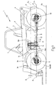
- Number 1 in Figure 1 indicates as a whole a motor vehicle with a telescopic lift arm, in accordance with the present invention.
- Vehicle 1 comprises a body 2 supported by a frame capable of supporting the weight of an arm 3, which comprises two telescopic portions 3a, 3b and is powered by a hydraulic drive assembly 4 located at the rear of the vehicle 1.
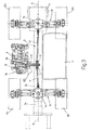
- Vehicle 1 also comprises a cab 5 housing a driver's seat 6 and a steering wheel 7. As shown more clearly in Figures 2 and 3, cab 5 is mounted laterally with respect to a longitudinal axis of symmetry A of vehicle 1 extending through center-line points P1 and P2 of respective axles 9 and 10 ( Figure 3). An engine 8 is mounted on the other side of longitudinal axis of symmetry A for simultaneously powering front axle 9 and rear axle 10 via a transmission defined respectively by a front propeller shaft 11 and a rear propeller shaft 12 ( Figure 3). Axles 9 and 10 are conventionally fitted with respective traction wheels 9a, 9b and 10a, 10b.
- Propeller shafts 11, 12 are connected by respective universal joints 13, 14 to a power transfer device or transmission device 15 which, in innovative manner and as will be seen later on, acts as a go-between between an engine transmission 16 and the universal joints 13, 14 which, as seen, transmit motion to front axle 9 and rear axle 10 respectively.
- a longitudinal axis of symmetry B of the engine drive shaft 8a lies in a horizontal plane S2 substantially parallel to a plane S1 containing longitudinal axis of symmetry A.
- Both planes S1 and S2 are substantially parallel to, but at different levels with respect to the ground So. More specifically, plane S2 is higher than S1, so that, as intended, all the significant mechanical parts as regards transmission of motion between engine 8 and propeller shafts 11, 12 are located substantially above plane S1, thus greatly reducing the risk of seriously damaging engine 8, transmission device 15, and/or transmission 16, in the event, for example, of one of the front wheels 9a, 9b or the rear wheels 10a, 10b accidentally sinking into the terrain.
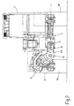
- transmission device 15 is located downstream from transmission 16 with respect to the transmission of motion from engine 8 to propeller shafts 11, 12. Together, transmission device 15 and transmission 16 define an innovative, substantially half-moon-shaped transmission unit 100.
- transmission 16 which is mechanical, is defined conventionally by a number of gears which mesh selectively to obtain a number of different ratios as requested by the driver.
- gears of transmission 16 are shown meshing in first forward gear. Transmission 16 further is of a conventional design and therefore not described in detail.
- shaft 16a of transmission 16 is fitted with the last gear 16b of transmission 16, and transmits motion, via a joint 16c, to a shaft 17a fitted with the first gear 15a of transmission device 15.
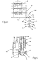
- device 15 comprises a casing 17 ( Figure 6) for supporting a number of shafts 17a-17d fitted with respective gears 15a-15d arranged in series and defining a gear train extending from the last gear 16b of transmission 16 to the two universal joints 13, 14 integral with shaft 17d of the last gear 15d.
- the universal joints 13, 14 motion is transmitted to propeller shafts 11, 12 and then to drive wheels 9a, 9b and 10a, 10b respectively.
- the shafts 17a-17d all extend in the previously defined plane S1.
- transmission 16 of unit 100 has an axis of substantial symmetry C lying in a plane of substantial symmetry S3, which advantageously, though not necessarily, slopes at an angle of 45° with respect to parallel planes S1, S2, whereas device 15 extends substantially parallel to the horizontal plane S1. In other words, whereas device 15 extends substantially horizontally, transmission 16 slopes at an angle of 45° so that unit 100 defined by device 15 and transmission 16 is substantially half-moon-shaped.
- a device 15 and a unit 100 in accordance with the present invention will be clear from the foregoing description. Foremost is the advantage of eliminating, for example, the chains of known transmission systems, thus reducing the occurrence of vibrations and improving reliability of the system as a whole. Moreover, the substantially half-moon shape of unit 100 provides for raising engine 8 with respect to ground So and lowering propeller shafts 11, 12 to conveniently transmit motion to wheels 9a, 9b and 10a, 10b. As such, the risk of collision between delicate elements such as the engine 8, the transmission unit 100, etc. with rough contours of the ground So, are greatly reduced.
- the particular shape of unit 100 also provides for achieving the compactness and reliability essential to vehicle 1.
- the transmission device 15 taps rotative power from the engine transmission 16 at shaft 16a, through which drive is transmitted in a rearward direction, i.e. opposite to the direction in which driving power enters the transmission 16 from the engine 8. Consequently, no extra space is required for the transmission device 15 on top of the engine transmission 16, reducing the overall length of the engine structure, whereby the spacing between the front and rear wheels 9a, 10a thus can be kept to a minimum, sufficient to house the combined engine/transmission structure.
- transmission unit 100 provides for getting underneath the side member of the frame without having to disrupt the shape of said side member. This is extremely important in terms of construction by enabling the use of a frame comprising two identical, straight side members, one right and one left, requiring no recesses in the vehicle body. Automated production of the two side members is therefore simplified considering that they can be identical as regards their longitudinal sides.
Landscapes
- Engineering & Computer Science (AREA)
- Transportation (AREA)
- Structural Engineering (AREA)
- Mechanical Engineering (AREA)
- General Engineering & Computer Science (AREA)
- Civil Engineering (AREA)
- Life Sciences & Earth Sciences (AREA)
- Geology (AREA)
- Arrangement Or Mounting Of Propulsion Units For Vehicles (AREA)
- Arrangement Of Transmissions (AREA)
- Vehicle Body Suspensions (AREA)
- Axle Suspensions And Sidecars For Cycles (AREA)
Claims (10)
- Kraftfahrzeug (1) mit:- einer Kabine (5);- einem Antriebsmotor (8), der seitlich bezüglich der Kabine (5) angeordnet ist;- einem Antriebsmotor-Getriebe (16), das betriebsmäßig mit dem Antriebsmotor (8) verbunden ist;- einem Teleskop-Hubarm (3), der in einer vorderen Arbeitsstellung zwischen der Kabine (5) und dem Antriebsmotor (8) liegt;- einer Vorder- und einer Hinterachse (9, 10), die Antriebsleistung von einem Paar von Antriebswellen (11, 12) erhalten;- einer Leistungsübertragungseinrichtung (10) mit einer im wesentlichen geradlinigen Form, die zwischen dem Antriebsmotor-Getriebe (16) und dem Paar von Antriebswellen (11, 12) angeordnet ist und einer Ausgangswelle (17d) aufweist, die mit den Antriebswellen (11, 12) über jeweilige Kreuzgelenke (13, 14) verbunden ist; wobei eine erste horizontale Ebene (S2) durch eine längsgerichtete Symmetrieachse (B) der Antriebsmotor-Abtriebswelle (8a) bezüglich des Bodens (so) oberhalb von einer zweiten horizontalen Ebene (S1) angeordnet ist, die die längsgerichtete Symmetrieachse (A) durch die Achsen (9, 10) enthält; und
dadurch gekennzeichnet, dass die Ausgangswelle (17d) im wesentlichen mit der Symmetrieachse (A) durch die Vorder- und Hinterachsen (9, 10) zusammenfällt. - Kraftfahrzeug (1) nach Anspruch 1, dadurch gekennzeichnet, dass die Leistungsübertragungseinrichtung (5) vollständig durch eine Anzahl von Zahnrädern (15a bis 15d) gebildet ist, die in Serie angeordnet sind.
- Kraftfahrzeug (1) nach Anspruch 2, dadurch gekennzeichnet, dass die die Leistungsübertragungseinrichtung (15) bildenden Zahnräder (15a bis 15d) in einem Gehäuse (17) angeordnet ist, wobei das Gehäuse (17) Wellen (17a bis 17d) lagert, die jeweils mit den Zahnrädern (15a bis 15d) verbunden sind.
- Kraftfahrzeug (1) nach Anspruch 3, dadurch gekennzeichnet, dass sich die zweite horizontale Ebene (S1) mittig durch die Leistungsübertragungseinrichtung (15) erstreckt.
- Kraftfahrzeug (1) nach Anspruch 4, dadurch gekennzeichnet, dass eine dritte Ebene (S3), die die Antriebsmotor-Ausgangswelle (8a) und die Antriebsmotor-Getriebe-Ausgangswelle (16a) umfasst, gegenüber der Horizontalen geneigt ist.
- Kraftfahrzeug (1) nach einem der vorhergehenden Ansprüche, dadurch gekennzeichnet, dass das Antriebsmotor-Getriebe (16) und die Leistungsübertragungseinrichtung (15) einstückig miteinander verbunden sind und eine Einheit (100) bilden.
- Kraftfahrzeug (1) nach Anspruch 7, dadurch gekennzeichnet, dass die Einheit (100) eine gewinkelte Form hat.
- Kraftfahrzeug (1) nach Anspruch 5 und einem der darauf zurückbezogenen Ansprüche, dadurch gekennzeichnet, dass sich die zweite horizontale Ebene (S1) und die dritte Ebene (S3) an der Antriebsmotor-Getriebe-Ausgangswelle (16a) schneiden.
- Kraftfahrzeug (1) nach einem der vorhergehenden Ansprüche , dadurch gekennzeichnet, dass bei Betrachtung in der Längsrichtung des Fahrzeugs (1) die Leistungsübertragungseinrichtung (15) sich nicht über das Antriebsmotor-Getriebe (16) hinaus erstreckt.
- Kraftfahrzeug (1) nach Anspruch 5 und einem der darauf zurückbezogenen Ansprüche, dadurch gekennzeichnet, dass sich zumindest ein Teil der Einheit (100) unter ein längsgerichtetes Seitenteil des Fahrzeugrahmens erstreckt.
Applications Claiming Priority (2)
| Application Number | Priority Date | Filing Date | Title |
|---|---|---|---|
| IT1998BO000646A IT1303973B1 (it) | 1998-11-20 | 1998-11-20 | Autoveicolo provvisto di braccio sollevatore telescopico . |
| ITBO980646 | 1998-11-20 |
Publications (2)
| Publication Number | Publication Date |
|---|---|
| EP1002759A1 EP1002759A1 (de) | 2000-05-24 |
| EP1002759B1 true EP1002759B1 (de) | 2006-02-01 |
Family
ID=11343515
Family Applications (1)
| Application Number | Title | Priority Date | Filing Date |
|---|---|---|---|
| EP99203718A Expired - Lifetime EP1002759B1 (de) | 1998-11-20 | 1999-11-08 | Kraftfahrzeug mit einer telescopischen Hebearmvorrichtung |
Country Status (4)
| Country | Link |
|---|---|
| US (1) | US6305488B1 (de) |
| EP (1) | EP1002759B1 (de) |
| DE (1) | DE69929653T2 (de) |
| IT (1) | IT1303973B1 (de) |
Families Citing this family (5)
| Publication number | Priority date | Publication date | Assignee | Title |
|---|---|---|---|---|
| US7017702B2 (en) * | 2002-10-11 | 2006-03-28 | William Gunby | Transport engine and drive arrangement |
| US7231848B2 (en) * | 2004-06-24 | 2007-06-19 | Magna Powertrain Usa, Inc. | Transfer case with dual chain transfer mechanism |
| US8256561B2 (en) * | 2007-04-16 | 2012-09-04 | Yamaha Hatsudoki Kabushiki Kaisha | Vehicle |
| US20080271940A1 (en) * | 2007-05-04 | 2008-11-06 | De Craemer Thomas M M | Transmission system for a vehicle |
| GB2470739A (en) * | 2009-06-02 | 2010-12-08 | Redrock Engineering Ltd | Telehandler vehicle having improved drive train layout |
Family Cites Families (8)
| Publication number | Priority date | Publication date | Assignee | Title |
|---|---|---|---|---|
| US2477252A (en) * | 1946-11-29 | 1949-07-26 | Hutchings Herschel | Agricultural tractor |
| US2978054A (en) * | 1954-07-02 | 1961-04-04 | Daimler Benz Ag | Axle-drive mechanism for motor vehicles |
| US4353429A (en) * | 1980-05-19 | 1982-10-12 | Herron Lonnie L | Overdrive unit for automotive vehicle |
| US5188193A (en) * | 1989-04-03 | 1993-02-23 | Liebherr-Werk Bischofshofen Ges.M.B.H. | Drive arrangement for earth moving machines |
| CA2009968C (en) * | 1990-02-13 | 1996-06-25 | Giovanni Bentivoglio | Boom operated fork truck |
| GB2268155B (en) * | 1992-06-30 | 1996-10-02 | Artix Ltd | Material handling machine |
| FR2713155B1 (fr) * | 1993-12-01 | 1996-01-26 | Manitou Bf | Chariot élévateur à bras télescopique. |
| US5931255A (en) * | 1997-05-09 | 1999-08-03 | Caterpillar Inc. | Power transfer arrangement for a machine |
-
1998
- 1998-11-20 IT IT1998BO000646A patent/IT1303973B1/it active
-
1999
- 1999-11-08 EP EP99203718A patent/EP1002759B1/de not_active Expired - Lifetime
- 1999-11-08 DE DE69929653T patent/DE69929653T2/de not_active Expired - Lifetime
- 1999-11-20 US US09/444,133 patent/US6305488B1/en not_active Expired - Lifetime
Also Published As
| Publication number | Publication date |
|---|---|
| IT1303973B1 (it) | 2001-03-01 |
| DE69929653D1 (de) | 2006-04-13 |
| ITBO980646A0 (it) | 1998-11-20 |
| ITBO980646A1 (it) | 2000-05-20 |
| DE69929653T2 (de) | 2006-07-20 |
| US6305488B1 (en) | 2001-10-23 |
| EP1002759A1 (de) | 2000-05-24 |
Similar Documents
| Publication | Publication Date | Title |
|---|---|---|
| EP2392485B1 (de) | Nutzfahrzeug | |
| US5964567A (en) | Skid steer loader vehicle | |
| AU2010241344B2 (en) | Cab suspension for a swather tractor | |
| US12377735B2 (en) | Work vehicle | |
| US12139026B2 (en) | Work vehicle | |
| EP1002759A1 (de) | Kraftfahrzeug mit einer telescopischen Hebearmvorrichtung | |
| US5758478A (en) | Front-mount mower tractor | |
| US5065831A (en) | Mounting arrangement for final drive unit for automotive vehicles | |
| US9381805B2 (en) | Tractor | |
| US4804060A (en) | Frame type tractor | |
| CN107531293B (zh) | 履带式拖拉机 | |
| US12565093B2 (en) | Inverter arrangement for an electric work vehicle | |
| EP0932729B1 (de) | Baggerfahrzeug mit rutschlenkung | |
| JP3847110B2 (ja) | 乗用型作業車 | |
| WO1993005974A1 (en) | Removable drive system for a skid steer loader | |
| US5564745A (en) | Automotive safety chassis | |
| EP0955226A3 (de) | Kipperfahrzeug | |
| EP0945396A2 (de) | Fahrzeug mit einem Ausleger wobei der Motor schräg zur Längsachse des Fahrzeuges angeordened ist | |
| EP4368435A1 (de) | Reisefahrzeug | |
| JP2816341B2 (ja) | 除雪用車両 | |
| JP3562534B2 (ja) | 車両の前輪駆動機構 | |
| EP3878677B1 (de) | Nutzfahrzeug | |
| JPH11334395A (ja) | トラクタの伝動装置 | |
| JP4627922B2 (ja) | クローラ式作業機 | |
| JP2003165349A (ja) | 移動農機 |
Legal Events
| Date | Code | Title | Description |
|---|---|---|---|
| PUAI | Public reference made under article 153(3) epc to a published international application that has entered the european phase |
Free format text: ORIGINAL CODE: 0009012 |
|
| AK | Designated contracting states |
Kind code of ref document: A1 Designated state(s): DE FR GB IT |
|
| AX | Request for extension of the european patent |
Free format text: AL;LT;LV;MK;RO;SI |
|
| 17P | Request for examination filed |
Effective date: 20001114 |
|
| AKX | Designation fees paid |
Free format text: DE FR GB IT |
|
| RAP1 | Party data changed (applicant data changed or rights of an application transferred) |
Owner name: CNH ITALIA S.P.A. |
|
| 17Q | First examination report despatched |
Effective date: 20041217 |
|
| GRAP | Despatch of communication of intention to grant a patent |
Free format text: ORIGINAL CODE: EPIDOSNIGR1 |
|
| GRAS | Grant fee paid |
Free format text: ORIGINAL CODE: EPIDOSNIGR3 |
|
| GRAA | (expected) grant |
Free format text: ORIGINAL CODE: 0009210 |
|
| AK | Designated contracting states |
Kind code of ref document: B1 Designated state(s): DE FR GB IT |
|
| PG25 | Lapsed in a contracting state [announced via postgrant information from national office to epo] |
Ref country code: IT Free format text: LAPSE BECAUSE OF FAILURE TO SUBMIT A TRANSLATION OF THE DESCRIPTION OR TO PAY THE FEE WITHIN THE PRESCRIBED TIME-LIMIT;WARNING: LAPSES OF ITALIAN PATENTS WITH EFFECTIVE DATE BEFORE 2007 MAY HAVE OCCURRED AT ANY TIME BEFORE 2007. THE CORRECT EFFECTIVE DATE MAY BE DIFFERENT FROM THE ONE RECORDED. Effective date: 20060201 |
|
| REG | Reference to a national code |
Ref country code: GB Ref legal event code: FG4D |
|
| REF | Corresponds to: |
Ref document number: 69929653 Country of ref document: DE Date of ref document: 20060413 Kind code of ref document: P |
|
| ET | Fr: translation filed | ||
| PLBE | No opposition filed within time limit |
Free format text: ORIGINAL CODE: 0009261 |
|
| STAA | Information on the status of an ep patent application or granted ep patent |
Free format text: STATUS: NO OPPOSITION FILED WITHIN TIME LIMIT |
|
| 26N | No opposition filed |
Effective date: 20061103 |
|
| REG | Reference to a national code |
Ref country code: DE Ref legal event code: R082 Ref document number: 69929653 Country of ref document: DE Representative=s name: PATENTANWAELTE WALLACH, KOCH & PARTNER, DE |
|
| REG | Reference to a national code |
Ref country code: DE Ref legal event code: R082 Ref document number: 69929653 Country of ref document: DE Representative=s name: PATENTANWAELTE WALLACH, KOCH, DR. HAIBACH, FEL, DE Effective date: 20140623 Ref country code: DE Ref legal event code: R082 Ref document number: 69929653 Country of ref document: DE Representative=s name: PATENTANWAELTE WALLACH, KOCH & PARTNER, DE Effective date: 20140623 Ref country code: DE Ref legal event code: R081 Ref document number: 69929653 Country of ref document: DE Owner name: CNH INDUSTRIAL ITALIA S.P.A., IT Free format text: FORMER OWNER: CNH ITALIA S.P.A., MODENA, IT Effective date: 20140623 |
|
| REG | Reference to a national code |
Ref country code: FR Ref legal event code: CD Owner name: CNH INDUSTRIAL ITALIA S.P.A. Effective date: 20150313 |
|
| REG | Reference to a national code |
Ref country code: FR Ref legal event code: PLFP Year of fee payment: 17 |
|
| REG | Reference to a national code |
Ref country code: FR Ref legal event code: PLFP Year of fee payment: 18 |
|
| REG | Reference to a national code |
Ref country code: FR Ref legal event code: PLFP Year of fee payment: 19 |
|
| PGFP | Annual fee paid to national office [announced via postgrant information from national office to epo] |
Ref country code: FR Payment date: 20171011 Year of fee payment: 19 Ref country code: DE Payment date: 20171011 Year of fee payment: 19 |
|
| PGFP | Annual fee paid to national office [announced via postgrant information from national office to epo] |
Ref country code: IT Payment date: 20171110 Year of fee payment: 19 Ref country code: GB Payment date: 20171006 Year of fee payment: 19 |
|
| REG | Reference to a national code |
Ref country code: DE Ref legal event code: R119 Ref document number: 69929653 Country of ref document: DE |
|
| GBPC | Gb: european patent ceased through non-payment of renewal fee |
Effective date: 20181108 |
|
| PG25 | Lapsed in a contracting state [announced via postgrant information from national office to epo] |
Ref country code: IT Free format text: LAPSE BECAUSE OF NON-PAYMENT OF DUE FEES Effective date: 20181108 Ref country code: DE Free format text: LAPSE BECAUSE OF NON-PAYMENT OF DUE FEES Effective date: 20190601 Ref country code: FR Free format text: LAPSE BECAUSE OF NON-PAYMENT OF DUE FEES Effective date: 20181130 |
|
| PG25 | Lapsed in a contracting state [announced via postgrant information from national office to epo] |
Ref country code: GB Free format text: LAPSE BECAUSE OF NON-PAYMENT OF DUE FEES Effective date: 20181108 |