EP1002757B1 - Lastträger für einen Wagenheber - Google Patents
Lastträger für einen Wagenheber Download PDFInfo
- Publication number
- EP1002757B1 EP1002757B1 EP99117403A EP99117403A EP1002757B1 EP 1002757 B1 EP1002757 B1 EP 1002757B1 EP 99117403 A EP99117403 A EP 99117403A EP 99117403 A EP99117403 A EP 99117403A EP 1002757 B1 EP1002757 B1 EP 1002757B1
- Authority
- EP
- European Patent Office
- Prior art keywords
- load carrier
- bearing
- transverse axis
- top part
- vehicle jack
- Prior art date
- Legal status (The legal status is an assumption and is not a legal conclusion. Google has not performed a legal analysis and makes no representation as to the accuracy of the status listed.)
- Expired - Lifetime
Links
- 238000002347 injection Methods 0.000 claims description 5
- 239000007924 injection Substances 0.000 claims description 5
- 210000002105 tongue Anatomy 0.000 description 11
- 229910000831 Steel Inorganic materials 0.000 description 6
- 239000010959 steel Substances 0.000 description 6
- 238000013459 approach Methods 0.000 description 5
- 238000004519 manufacturing process Methods 0.000 description 4
- 238000000034 method Methods 0.000 description 4
- NJPPVKZQTLUDBO-UHFFFAOYSA-N novaluron Chemical compound C1=C(Cl)C(OC(F)(F)C(OC(F)(F)F)F)=CC=C1NC(=O)NC(=O)C1=C(F)C=CC=C1F NJPPVKZQTLUDBO-UHFFFAOYSA-N 0.000 description 4
- 239000000969 carrier Substances 0.000 description 3
- 239000002184 metal Substances 0.000 description 2
- 229920004943 Delrin® Polymers 0.000 description 1
- 208000004067 Flatfoot Diseases 0.000 description 1
- 230000001154 acute effect Effects 0.000 description 1
- 238000010276 construction Methods 0.000 description 1
- 230000002950 deficient Effects 0.000 description 1
- 239000010985 leather Substances 0.000 description 1
- 239000000243 solution Substances 0.000 description 1
Images



Classifications
-
- B—PERFORMING OPERATIONS; TRANSPORTING
- B66—HOISTING; LIFTING; HAULING
- B66F—HOISTING, LIFTING, HAULING OR PUSHING, NOT OTHERWISE PROVIDED FOR, e.g. DEVICES WHICH APPLY A LIFTING OR PUSHING FORCE DIRECTLY TO THE SURFACE OF A LOAD
- B66F3/00—Devices, e.g. jacks, adapted for uninterrupted lifting of loads
- B66F3/08—Devices, e.g. jacks, adapted for uninterrupted lifting of loads screw operated
- B66F3/12—Devices, e.g. jacks, adapted for uninterrupted lifting of loads screw operated comprising toggle levers
Definitions
- the invention relates to a jack with a load carrier and with a pedestal that can be placed on the floor, this is attached to a first transverse axis, two side walls having support arm, one of the pivoting of the support arm Serving threaded spindle, for those in the area of the upper Stand column end a first axial bearing and on the support arm in the Distance from the first transverse axis a second thrust bearing is provided, as well as with a hand crank on the column side End of the threaded spindle, the one on a body attachable load carriers in its lower area each side a storage approach for storing the Load carrier in openings in the support arm side walls such that the load carrier relative to the support arm about a to the first transverse axis parallel second transverse axis is pivotable, and a Channel for the passage of the threaded spindle and for the controlled one Swiveling the load carrier around by the threaded spindle has the second transverse axis.
- the load carrier of the jack according to EP-0 340 551-B1 is specially designed for use on vehicles whose Body in those areas where the jack should be applied with one in the longitudinal direction of the vehicle extending and pointing downward web is, namely the so-called sill seam web. Therefore points the load carrier of this jack in its upper area a groove, which opens upwards, from the Top of the load carrier extends down and for the Recording of the sill seam web is provided.
- This well-known jack is therefore also suitable for Handling inexperienced people, of course, how to position the jack on the vehicle body, namely so that the sill seam engages in said groove.
- the present invention is concerned with jacks of another type, namely those whose load carriers are from below against a seamless body attachment area is, and in such a case one can handle jacks Inexperienced person easily lift the jack in a wrong way Starting position, which is then the risk brings that jack when lifting the vehicle slips and / or the vehicle body is damaged.
- the top of the load carrier is more or less educated, at least when looking at the Load carrier in the direction of the second transverse axis, d. H. in the direction the axis around which the load carrier is lifted of the vehicle pivoted relative to the jack arm or in a direction perpendicular to this.
- the E.A. Storz GmbH & Co. KG now has a jack of the type mentioned in the introduction, in which the load carrier one with the bearing approaches for one pivoting mounting of the load carrier on the support arm, as well as with the channel for the passage of the threaded spindle Lower part and one that can be placed against the body from below Has upper part, which with the load carrier lower part one parallel to the second transverse axis and above the latter extending third transverse axis is pivotally connected.
- the load carrier upper part including the two bearing cheeks and the lower part of the load carrier together with the both journals are each made as one-piece plastic injection molded parts designed, and that in the two cheeks
- the proposed storage openings are designed as open at the bottom Openings formed, in such a way that the Load carrier upper part from above onto the load carrier lower part can snap on, with elastic expansion of the extending downward from the actual storage openings Slits of the bearing cheeks; after snapping on the
- the upper part of the load carrier is the bearing journal of the lower part of the load carrier in said storage openings.
- Upper and lower part of the load carrier are provided with stops which the Swiveling of the upper part of the load carrier relative to the lower part of the load carrier limit, d. H.
- the top of the load carrier top is for placing against a seamless body attachment area designed, d. H. the load carrier upper part does not have a groove for inserting a sill seam web.
- a steel wire spring is arranged, through which the unloaded Load carrier top always in that of his two End positions is pivoted in when the jack is on the body of the vehicle to be lifted is attached,
- the top of the load carrier upper part is not yet loaded (seen in the direction of its pivot axis) with the Axis of the jack screw spindle is relatively forms a small angle, the tip of which is towards the crank handle Threaded spindle end has - this angle is approximately 15 °.
- the invention was based on the object of this known Jack from E.A. Storz GmbH & Co. KG to improve that at least one of the two shown above Risks can be avoided.
- the invention also proposes a solution to the problem that the user of the jack due to the inclination of the Top of the one in its end position Load carrier upper part is tempted to the jack incorrectly set (so that it can slip off) if at intact wheels and unladen vehicle a wheel to be replaced.
- Embodiments are preferred in which in the starting position the top of the load carrier its top - in Direction of the third transverse axis or seen perpendicular to it - One with the axis of the channel of the lower part of the load carrier such angle forms that when putting on the not yet loaded Load carrier upper part against the body attachment area of an unladen vehicle with intact wheels the top of the load carrier top approximately parallel to Body attachment area runs.
- the spring is now proposed to form one of the load carrier parts and this load carrier part to be designed as a plastic injection molded part. Then can neither the described rattling noises occur, nor must the spring is manufactured and assembled separately; Moreover the spring is attached absolutely captive.
- one of the two springs on one could Load carrier part and the other spring on the other load carrier part be provided for manufacturing and assembly reasons however, preferred embodiments in which both Springs are attached to the same load carrier part.
- the spring or springs could be bow-shaped and fixed on both sides to one of the load carrier parts be, especially with regard to the manufacture of the Load carrier, however, it is more advantageous if each spring than a one-sided spring tongue is formed, which - in the top view of the load carrier - across Pivot axis of the upper part of the load carrier extends.
- both Springs are attached to the lower part of the load carrier and at least with the top part of the load carrier unloaded against its underside issue.
- This not only has manufacturing and assembly advantages, but also leads to a particularly stable starting position of the upper part of the load carrier.
- the latter applies especially for embodiments in which the two springs - in Seen in the direction of the pivot axis of the upper part of the load carrier - form a flat, upward opening V, in particular then when the two springs - towards this Seen pivot axis - approximately from the circumference of the bearing pins stretch tangentially.
- a jack of the type mentioned with a two-part Load carrier the upper part of which can be pivoted on the lower part of the load carrier is articulated from DE-196 25 281-A1 E.A. Storz GmbH & Co. KG emerges; just like that Vehicle jack according to EP-0 340 551-B1 also relates to the DE-196 25 281-A1 expressly only includes jacks for Start in the area of a sill seam so that the swiveling load carrier upper part an opening upwards Has groove for the engagement of the sill seam web.
- Fig. 1 shows such a jack in one Side view and in a state after the support arm has already been swung up over part of its stroke.
- Fig. 1 The known jack shown in Fig. 1 is in the following can only be described to the extent that this is for understanding the basic structure and the function of such Jack is required for which the invention Load carrier is provided.
- the jack shown in Fig. 1 has a pedestal 10, a support arm 12, a load carrier 14, a threaded spindle 16, a hinged to this crank 20 and one attached to the lower end of the pedestal 10, angled Base plate 22 on.
- the pedestal 10 consists of a Cross section of U-shaped sheet metal profile with two side walls 24 and a rear wall connecting them.
- Also with the support arm 12 is a U-shaped cross section Sheet metal profile with two side walls 28 and a connecting these Bottom 30, which is slightly narrower than the rear wall 26 the column 10 so that the support arm 12 with its according to FIG. 1 right end between the side walls 24 of the pillar engage and by means of a bolt 34 in the side walls 24 can be pivoted.
- the pin 34 defines thus the first transverse axis in the sense of the claims.
- Fig. 1 an area of the front bracket side wall 28 broken away to show better how the Load carrier 14 is mounted on the support arm 12.
- the load carrier 14 (like the one to be described later load carrier according to the invention) preferably from a plastic manufactured under the registered Trademark DELRIN is available on the market, or from a plastic with similar properties. Different from that load carrier according to the invention to be described has the in Fig. 1 shown load carrier 14 an opening upwards Groove 36 for receiving a sill seam web of the body of the vehicle which is connected to the jack according to FIG. 1 should be raised; the one to be placed against the underside of the body and the lifting load-bearing top of the load carrier 14 was designated 38.
- the load carrier 14 has a possibly graded Channel 56 with smooth wall for the passage of the threaded spindle 16, while in the nut 46 a channel 58 with a Nut thread for the threaded spindle 16 is formed.
- the left end of the threaded spindle 16 according to FIG. 1 is one mushroom-shaped head 60 formed between the and the load carrier 14, an axial bearing 62 designed as a roller bearing is arranged is.
- the bearing lugs 40 of the load carrier 14 or the bearing openings Define 44 in the support arm side walls 28 the second transverse axis in the sense of the appended claims.
- the load carrier 70 in a side view accordingly the representation of the load carrier 14 in Fig. 1.
- the load carrier 70 consists essentially of a lower part of the load carrier 72 and a load carrier upper part 74, which is articulated are interconnected.
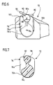
- 6 and 7 results are on the body of the load carrier lower part 72 molded on both sides of the bearing lugs, which have a disk-like end plate 76a and between this as well as the actual body of the lower part of the load carrier 72 each form a part-circular groove 76b. In these grooves can the edges of the bearing openings 44 of the in Fig.
- the lower part 72 of the invention Load carrier 70 a channel 80 crossing the lower part on.
- the lower part of the load carrier is above the bearing lugs 76 72 provided on both sides with a bearing pin 82, the An oblique end face in its upper area 82a forms, the sloping end faces of these of the two trunnions 82 defined planes obliquely upwards to run towards each other to create sliding surfaces for the from above load carrier upper part to be snapped onto the load carrier lower part 72 74 form, as described in more detail later will be.
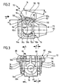
- the load carrier lower part designed as a plastic injection molded part 72 two spring tongues 84 and 86 molded according to the invention; these spring tongues are on the top of the lower part of the load carrier provided and to be discussed later Way specially designed and oriented.
- these spring tongues transverse to one of the coaxial journals 82 defined pivot axis 88, which is the third Cross axis in the sense of the appended claims.
- FIGS. 4 and 5 show the two spring tongues 84, 86 in the unloaded Condition and also show that the spring tongues are inclined differently in this state and - viewed in the direction of the pivot axis 88 - approximately Extend tangentially from the circumference of the trunnion, namely roughly in opposite directions.
- the load carrier upper part 74 shown in FIGS. 8-14 is provided on both sides with a bearing cheek 90, which a circular bearing openings 90a for storing the load carrier upper part 74 on the two journals 82 of the lower part of the load carrier 72 has.
- a bearing cheek 90 which a circular bearing openings 90a for storing the load carrier upper part 74 on the two journals 82 of the lower part of the load carrier 72 has.
- Figures 8-14 is also the pivot axis 88 indicated. Although it is also as Plastic injection molded part manufactured load carrier upper part 74 is heavily ribbed, it forms - in the direction of the swivel axis 88 seen - a substantially flat top 92 as well flat underside areas 94, all in one to the top 92 parallel plane.
- Bearing cheeks 90 can be deflected elastically (in the direction of the swivel axis 88), although with considerable effort Forces - the bearing cheeks 90 must be so dimensionally stable that the lifting force to be absorbed by the load carrier upper part 74 over the bearing cheeks 90 into the bearing journal 82 of the lower part of the load carrier 72 can initiate.
- Rib-shaped regions of the lower part 72 of the load carrier form whose top stops 100, which correspond to the direction of the Axis of the channel 80 is relatively small form an acute angle ⁇ , which is in particular about 15 °.
- Underside areas act with these stops 100 94 of the load carrier upper part 74 together to the pivoting of the upper part of the load carrier compared to the lower part of the load carrier limit in both directions and thus end positions of the Define load carrier upper part 74.
- the spring tongues 84 and 86 are arranged that these also with underside areas 94 of the load carrier upper part 74 cooperate, d. H. against such underside areas 94 rest, according to the invention the two spring tongues 84 and 86 are designed, designed and arranged so that when the load carrier upper part 74 is unloaded, the upper side thereof 92 with the direction of the axis of the channel 80 an angle ⁇ forms, which is smaller than the angle ⁇ and preferably is approximately 13 °. 2 shows the load carrier upper part 74 in an unloaded state, d. H. in its starting position, and also shows the angle ⁇ . It is now understandable which is why the spring tongues 84 and 86 are different are inclined.
- the lower part of the load carrier on the support arm could also fixed, but in any case be attached so that it cannot be pivoted; therefore the lower part of the load carrier does not necessarily have to be included Storage approaches and / or with a channel for passage the threaded spindle.
Landscapes
- Life Sciences & Earth Sciences (AREA)
- Engineering & Computer Science (AREA)
- Geology (AREA)
- Mechanical Engineering (AREA)
- Structural Engineering (AREA)
- Vehicle Cleaning, Maintenance, Repair, Refitting, And Outriggers (AREA)
- Invalid Beds And Related Equipment (AREA)
Description
- Fig. 2
- eine Seitenansicht des erfindungsgemäßen Lastträgers, welche der in Fig. 1 dargestellten Seitenansicht des bekannten Lastträgers entspricht;
- Fig. 3
- eine Frontansicht des Unterteils der erfindungsgemäßen Lastträgers, gesehen in Richtung des Pfeils A in Fig. 2;
- Fig. 4 und 5
- Schnitte durch das Lastträger-Unterteil entsprechend den Linien 4-4 und 5-5 in Fig. 3;
- Fig. 6
- eine der Fig. 2 entsprechende Seitenansicht nur des Lastträger-Unterteils;
- Fig. 7
- einen Schnitt durch das Lastträger-Unterteil entsprechend der Linie 7-7 in Fig. 3;
- Fig. 8
- eine Seitenansicht des Lastträger-Oberteils, gesehen in Richtung seiner Schwenkachse;
- Fig. 9
- eine Draufsicht auf das Lastträger-Oberteil;
- Fig. 10
- eine Ansicht des Lastträger-Oberteils von vorn, gesehen in Richtung des Pfeils B in Fig. 8;
- Fig. 11
- eine Ansicht des Lastträger-Oberteils von unten;
- Fig. 12
- einen Schnitt durch das Lastträger-Oberteil gemäß der Linie 12-12 in Fig. 10;
- Fig. 13
- einen Schnitt durch das Lastträger-Oberteil entsprechend der Linie 13-13 in Fig. 11, und
- Fig. 14
- einen Schnitt durch das Lastträger-Oberteil gemäß der Linie 14-14 in Fig. 9.
Claims (13)
- Wagenheber mit einem Lastträger (70) und mit einer auf den Boden aufsetzbaren Standsäule (10), einem an dieser um eine erste Querachse (34) schwenkbar angebrachten, zwei Seitenwände (28) aufweisenden Tragarm (12), einer dem Verschwenken des Tragarms dienenden Gewindespindel (16), für die im Bereich des oberen Standsäulenendes ein erstes Axiallager (46) und im Abstand von der ersten Querachse im Bereich des Tragarms ein zweites Axiallager (44, 72, 62) vorgesehen ist, sowie mit einer Handkurbel (20) am Standsäulen-seitigen Ende der Gewindespindel, wobei der an einer Karosserie ansetzbare Lastträger in seinem unteren Bereich aufweistund wobei der Lastträger (70) ein mit den Lagerungsansätzen (76) und dem Kanal (80) versehenes Unterteil (72) sowie ein von unten gegen die Karosserie anlegbares Oberteil (74) aufweist, welches mit dem Lastträger-Unterteil um eine zur zweiten Querachse (76c) parallele sowie oberhalb der letzteren verlaufende dritte Querachse (88) über zwei Gelenke (90, 90a, 82) schwenkbar verbunden ist, deren Gelenkachsen mit der dritten Querachse (88) zusammenfallen und von denen jedes einen am Lastträger-Unterteil (72) angebrachten und von diesem seitlich abstehenden Lagerzapfen (82) sowie eine am Lastträger-Oberteil (74) seitlich angebrachte Lagerwange (90) mit einer einen geschlossenen Rand aufweisenden Lageröffnung (90a) zum Lagern auf den Lagerzapfen aufweist, dadurch gekennzeichnet, daß die Lagerwangen (90) in Richtung der Gelenkachsen (88) elastisch auslenkbar ausgebildet sind, und daß die Lagerzapfen (82) und/oder die Lagerwangen an ihren freien Enden mit zur Gelenkachse (88) derart schräg verlaufenden Stirnflächen (82a) bzw. Innenflächen versehen sind, daß sich die Lageröffnungen (90a) unter elastischer Auslenkung der Lagerwangen (90) auf die Lagerzapfen (82) aufrasten lassen.(a) auf jeder Seite jeweils einen Lagerungsansatz (76) zum Lagern des Lastträgers in Öffnungen (44) der Tragarmseitenwände (28) derart, daß der Lastträger relativ zum Tragarm um eine zur ersten Querachse parallele zweite Querachse (76c) schwenkbar ist, und(b) einen Kanal (80) zum Hindurchführen der Gewindespindel und zum gesteuerten Verschwenken des Lastträgers durch die Gewindespindel um die zweite Querachse,
- Wagenheber nach Anspruch 1, dadurch gekennzeichnet, daß die von den Lagerzapfen-Stirnflächen (82a) definierten Ebenen nach oben aufeinander zu verlaufen.
- Wagenheber nach Anspruch 1 oder 2, dadurch gekennzeichnet, daß die Oberseite (92) des Lastträger-Oberteils (74) zum Anlegen gegen einen steglosen Karosserieansetzbereich gestaltet ist.
- Wagenheber nach einem oder mehreren der vorstehenden Ansprüche, dadurch gekennzeichnet, daß das Lastträger-Oberteil (74) um die dritte Querachse (88) zwischen zwei Endstellungen schwenkbar und eine zwischen Lastträger-Oberteil und Lastträger-Unterteil (72) angeordnete Feder (84, 86) zum Schwenken des unbelasteten Lastträger-Oberteils in eine Oberteil-Ausgangsstellung vorgesehen ist, wobei die Feder (84, 86) derart gestaltet ist, daß die Oberteil-Ausgangsstellung zwischen den beiden Endstellungen des Lastträger-Oberteils (74) liegt.
- Wagenheber nach den Ansprüchen 3 und 4, dadurch gekennzeichnet, daß in der Ausgangsstellung des Lastträger-Oberteils (74) dessen Oberseite (92) - in Richtung der dritten Querachse (88) gesehen - mit der Achse des Kanals (80) des Lastträger-Unterteils (72) einen solchen Winkel (β) bildet, daß beim Anlegen des noch nicht belasteten Lastträger-Oberteils (74) gegen den Karosserieansetzbereich eines unbeladenen Fahrzeugs mit intakten Laufrädern die Oberseite (92) des Lastträger-Oberteils ungefähr parallel zum Karosserieansetzbereich verläuft.
- Wagenheber nach Anspruch 4 oder 5, dadurch gekennzeichnet, daß die Feder (84, 86) eine Kunststoffeder ist.
- Wagenheber nach Anspruch 6, dadurch gekennzeichnet, daß die Feder (84, 86) an eines der Lastträgerteile (72, 74) angeformt und dieses Lastträgerteil als Kunststoffspritzgußteil ausgebildet ist.
- Wagenheber nach einem oder mehreren der Ansprüche 4 bis 7, dadurch gekennzeichnet, daß zwei einander entgegengerichtete Schwenkbewegungen des Lastträger-Oberteils (74) bewirkende Federn (84, 86) vorgesehen sind, welche so gestaltet und angeordnet sind, daß das unbelastete Lastträger-Oberteil (74) bezüglich des Lastträger-Unterteils (72) seine Ausgangsstellung einnimmt.
- Wagenheber nach Anspruch 8, dadurch gekennzeichnet, daß beide Federn (84, 86) am selben Lastträgerteil (72) angebracht sind.
- Wagenheber nach Anspruch 8 oder 9, dadurch gekennzeichnet, daß jede Feder (84, 86) als eine einseitig festgelegte Federzunge ausgebildet ist, welche sich - in der Draufsicht auf den Lastträger (70) - quer zur dritten Querachse (88) erstreckt.
- Wagenheber nach Anspruch 10, dadurch gekennzeichnet, daß beide Federn (84, 86) am Lastträger-Unterteil (72) angebracht sind und zumindest bei unbelastetem Lastträger-Oberteil (74) gegen dessen Unterseite (94) anliegen.
- Wagenheber nach Anspruch 11, dadurch gekennzeichnet, daß die beiden Federn (84, 86) - in Richtung der dritten Querachse (88) gesehen - ein sich nach oben öffnendes V bilden.
- Wagenheber nach Anspruch 12, dadurch gekennzeichnet, daß die beiden Federn (84, 86) - in Richtung der dritten Querachse (88) gesehen - sich vom Umfang der Lagerzapfen (82) ungefähr tangential wegerstrecken.
Applications Claiming Priority (2)
| Application Number | Priority Date | Filing Date | Title |
|---|---|---|---|
| DE29820811U | 1998-11-20 | ||
| DE29820811U DE29820811U1 (de) | 1998-11-20 | 1998-11-20 | Lastträger für einen Wagenheber |
Publications (2)
| Publication Number | Publication Date |
|---|---|
| EP1002757A1 EP1002757A1 (de) | 2000-05-24 |
| EP1002757B1 true EP1002757B1 (de) | 2003-07-02 |
Family
ID=8065635
Family Applications (2)
| Application Number | Title | Priority Date | Filing Date |
|---|---|---|---|
| EP99117403A Expired - Lifetime EP1002757B1 (de) | 1998-11-20 | 1999-09-07 | Lastträger für einen Wagenheber |
| EP99117450A Withdrawn EP1002758A1 (de) | 1998-11-20 | 1999-09-08 | Lastträger für einen Wagenheber |
Family Applications After (1)
| Application Number | Title | Priority Date | Filing Date |
|---|---|---|---|
| EP99117450A Withdrawn EP1002758A1 (de) | 1998-11-20 | 1999-09-08 | Lastträger für einen Wagenheber |
Country Status (3)
| Country | Link |
|---|---|
| EP (2) | EP1002757B1 (de) |
| DE (2) | DE29820811U1 (de) |
| ES (1) | ES2205659T3 (de) |
Families Citing this family (1)
| Publication number | Priority date | Publication date | Assignee | Title |
|---|---|---|---|---|
| EP2181957A1 (de) | 2008-11-03 | 2010-05-05 | Scambia Industrial Developments AG | Grundplatte für Hebevorrichtungen |
Family Cites Families (6)
| Publication number | Priority date | Publication date | Assignee | Title |
|---|---|---|---|---|
| GB664718A (en) * | 1949-06-14 | 1952-01-09 | Smith S Jacking Systems Ltd | Improvements in or relating to lifting devices |
| DE68901620D1 (de) * | 1988-01-18 | 1992-07-02 | Batz S Coop Ltda | Wagenheber. |
| DE58900895D1 (de) * | 1988-05-05 | 1992-04-09 | Storz E A Kg | Wagenheber. |
| ES1013831Y (es) * | 1990-04-10 | 1991-06-16 | Salvador Rovira Xavier | Gato mecanico mejorado para vehiculos automoviles. |
| DE9418720U1 (de) * | 1994-11-24 | 1995-01-12 | Panne GmbH & Co KG Grundstücksgesellschaft, 35753 Greifenstein | Wagenheber für Kfz. |
| DE19625281A1 (de) * | 1996-06-25 | 1998-01-08 | Storz E A Kg | Wagenheber |
-
1998
- 1998-11-20 DE DE29820811U patent/DE29820811U1/de not_active Expired - Lifetime
-
1999
- 1999-09-07 DE DE59906173T patent/DE59906173D1/de not_active Expired - Lifetime
- 1999-09-07 EP EP99117403A patent/EP1002757B1/de not_active Expired - Lifetime
- 1999-09-07 ES ES99117403T patent/ES2205659T3/es not_active Expired - Lifetime
- 1999-09-08 EP EP99117450A patent/EP1002758A1/de not_active Withdrawn
Also Published As
| Publication number | Publication date |
|---|---|
| EP1002757A1 (de) | 2000-05-24 |
| DE59906173D1 (de) | 2003-08-07 |
| EP1002758A1 (de) | 2000-05-24 |
| DE29820811U1 (de) | 2000-03-23 |
| ES2205659T3 (es) | 2004-05-01 |
Similar Documents
| Publication | Publication Date | Title |
|---|---|---|
| DE3888364T3 (de) | Eine lasttragende vorrichtung. | |
| EP0061715A2 (de) | Sportschuh mit einer mit Greifelementen versehenen Sohle | |
| EP0951320A1 (de) | Rollbrett sowie dazugehörige fussbremse | |
| DD238726A5 (de) | Fuehrungsvorrichtung eines schischuhes, und an diese vorrichtung angepasster schuh und schigrundflaeche | |
| DE69501940T2 (de) | Abnehmbare Befestigung eines Fahrzeugsitzuntergestells auf einem Boden | |
| DE19711046A1 (de) | Seilfensterheber | |
| DE3128169C2 (de) | Abnehmbarer Tragegriff | |
| DE2851980A1 (de) | Wagenheber | |
| DE3325833A1 (de) | Tuerspiegelvorrichtung fuer automobile | |
| DE2649101A1 (de) | Ausbildung einer abschlusskappe, insbesondere fuer moebel wie drehsessel | |
| EP0340551B1 (de) | Wagenheber | |
| DE8717019U1 (de) | Höhenverstellbare Stütze, insbesondere mittels Handkurbel betätigbare Stütze für Sattelanhänger | |
| WO2017055340A1 (de) | Beschlag für eine schiebetür und verfahren zur montage einer schiebetür | |
| DE69607587T2 (de) | Provisorischer türanschlag für ein kraftfahrzeugscharnier und vorrichtung um diesen anzubringen | |
| DE3248260A1 (de) | Scharnier sowie dessen verwendung fuer die befestigung von wc-deckel und/oder -brille | |
| EP1002758A1 (de) | Lastträger für einen Wagenheber | |
| EP0234525B1 (de) | Halterung zum Befestigen eines Wischblatts mit Gelenkbolzen an einem hakenförmigen Wischarm | |
| DE3433589C2 (de) | ||
| DE3510196C2 (de) | Wagenheber | |
| DE202006009707U1 (de) | Felge für ein Rad mit Zugspeichen und Rad, welches eine derartige Felge aufweist | |
| DE3344611C2 (de) | ||
| DE8904337U1 (de) | Scharnier für eine Kraftfahrzeugtür | |
| DE3324838C2 (de) | Hebedach für Fahrzeuge | |
| DE2756108C2 (de) | Wagenheber | |
| DE69100009T2 (de) | Wagenheber. |
Legal Events
| Date | Code | Title | Description |
|---|---|---|---|
| PUAI | Public reference made under article 153(3) epc to a published international application that has entered the european phase |
Free format text: ORIGINAL CODE: 0009012 |
|
| AK | Designated contracting states |
Kind code of ref document: A1 Designated state(s): DE ES FR GB |
|
| AX | Request for extension of the european patent |
Free format text: AL;LT;LV;MK;RO;SI |
|
| 17P | Request for examination filed |
Effective date: 20001020 |
|
| AKX | Designation fees paid |
Free format text: DE ES FR GB |
|
| GRAH | Despatch of communication of intention to grant a patent |
Free format text: ORIGINAL CODE: EPIDOS IGRA |
|
| GRAH | Despatch of communication of intention to grant a patent |
Free format text: ORIGINAL CODE: EPIDOS IGRA |
|
| GRAA | (expected) grant |
Free format text: ORIGINAL CODE: 0009210 |
|
| AK | Designated contracting states |
Designated state(s): DE ES FR GB |
|
| REG | Reference to a national code |
Ref country code: GB Ref legal event code: FG4D Free format text: NOT ENGLISH |
|
| REF | Corresponds to: |
Ref document number: 59906173 Country of ref document: DE Date of ref document: 20030807 Kind code of ref document: P |
|
| GBT | Gb: translation of ep patent filed (gb section 77(6)(a)/1977) |
Effective date: 20031029 |
|
| REG | Reference to a national code |
Ref country code: ES Ref legal event code: FG2A Ref document number: 2205659 Country of ref document: ES Kind code of ref document: T3 |
|
| ET | Fr: translation filed | ||
| PLBE | No opposition filed within time limit |
Free format text: ORIGINAL CODE: 0009261 |
|
| STAA | Information on the status of an ep patent application or granted ep patent |
Free format text: STATUS: NO OPPOSITION FILED WITHIN TIME LIMIT |
|
| 26N | No opposition filed |
Effective date: 20040405 |
|
| REG | Reference to a national code |
Ref country code: GB Ref legal event code: 732E |
|
| REG | Reference to a national code |
Ref country code: ES Ref legal event code: PC2A |
|
| REG | Reference to a national code |
Ref country code: FR Ref legal event code: TP |
|
| PGFP | Annual fee paid to national office [announced via postgrant information from national office to epo] |
Ref country code: FR Payment date: 20100921 Year of fee payment: 12 |
|
| PGFP | Annual fee paid to national office [announced via postgrant information from national office to epo] |
Ref country code: GB Payment date: 20100901 Year of fee payment: 12 |
|
| PGFP | Annual fee paid to national office [announced via postgrant information from national office to epo] |
Ref country code: DE Payment date: 20101027 Year of fee payment: 12 |
|
| PGFP | Annual fee paid to national office [announced via postgrant information from national office to epo] |
Ref country code: ES Payment date: 20101018 Year of fee payment: 12 |
|
| GBPC | Gb: european patent ceased through non-payment of renewal fee |
Effective date: 20110907 |
|
| REG | Reference to a national code |
Ref country code: FR Ref legal event code: ST Effective date: 20120531 |
|
| REG | Reference to a national code |
Ref country code: DE Ref legal event code: R119 Ref document number: 59906173 Country of ref document: DE Effective date: 20120403 |
|
| PG25 | Lapsed in a contracting state [announced via postgrant information from national office to epo] |
Ref country code: DE Free format text: LAPSE BECAUSE OF NON-PAYMENT OF DUE FEES Effective date: 20120403 |
|
| PG25 | Lapsed in a contracting state [announced via postgrant information from national office to epo] |
Ref country code: GB Free format text: LAPSE BECAUSE OF NON-PAYMENT OF DUE FEES Effective date: 20110907 Ref country code: FR Free format text: LAPSE BECAUSE OF NON-PAYMENT OF DUE FEES Effective date: 20110930 |
|
| REG | Reference to a national code |
Ref country code: ES Ref legal event code: FD2A Effective date: 20131030 |
|
| PG25 | Lapsed in a contracting state [announced via postgrant information from national office to epo] |
Ref country code: ES Free format text: LAPSE BECAUSE OF NON-PAYMENT OF DUE FEES Effective date: 20110908 |