EP1002716A1 - Methode und Vorrichtung zur Lageregelung eines Satelliten - Google Patents
Methode und Vorrichtung zur Lageregelung eines Satelliten Download PDFInfo
- Publication number
- EP1002716A1 EP1002716A1 EP99401843A EP99401843A EP1002716A1 EP 1002716 A1 EP1002716 A1 EP 1002716A1 EP 99401843 A EP99401843 A EP 99401843A EP 99401843 A EP99401843 A EP 99401843A EP 1002716 A1 EP1002716 A1 EP 1002716A1
- Authority
- EP
- European Patent Office
- Prior art keywords
- cluster
- attitude
- satellite
- gyrodynes
- angular
- Prior art date
- Legal status (The legal status is an assumption and is not a legal conclusion. Google has not performed a legal analysis and makes no representation as to the accuracy of the status listed.)
- Granted
Links
- 238000000034 method Methods 0.000 title claims abstract description 18
- 239000011159 matrix material Substances 0.000 claims description 3
- 230000004044 response Effects 0.000 claims description 3
- 238000001914 filtration Methods 0.000 claims description 2
- 230000001133 acceleration Effects 0.000 description 3
- 238000013459 approach Methods 0.000 description 3
- 238000006243 chemical reaction Methods 0.000 description 3
- 238000004804 winding Methods 0.000 description 2
- 235000001674 Agaricus brunnescens Nutrition 0.000 description 1
- 238000005452 bending Methods 0.000 description 1
- 230000005540 biological transmission Effects 0.000 description 1
- 238000004364 calculation method Methods 0.000 description 1
- 230000008859 change Effects 0.000 description 1
- 238000007796 conventional method Methods 0.000 description 1
- 230000008878 coupling Effects 0.000 description 1
- 238000010168 coupling process Methods 0.000 description 1
- 238000005859 coupling reaction Methods 0.000 description 1
- 238000010586 diagram Methods 0.000 description 1
- 238000006073 displacement reaction Methods 0.000 description 1
- 230000000694 effects Effects 0.000 description 1
- 238000005259 measurement Methods 0.000 description 1
- 230000007246 mechanism Effects 0.000 description 1
- 238000012986 modification Methods 0.000 description 1
- 230000004048 modification Effects 0.000 description 1
- 230000003287 optical effect Effects 0.000 description 1
- 230000005693 optoelectronics Effects 0.000 description 1
- 210000000056 organ Anatomy 0.000 description 1
- 230000003071 parasitic effect Effects 0.000 description 1
- 238000012545 processing Methods 0.000 description 1
- 230000009467 reduction Effects 0.000 description 1
- 238000004513 sizing Methods 0.000 description 1
- 238000009987 spinning Methods 0.000 description 1
- 230000001052 transient effect Effects 0.000 description 1
- 230000002618 waking effect Effects 0.000 description 1
Images
Classifications
-
- B—PERFORMING OPERATIONS; TRANSPORTING
- B64—AIRCRAFT; AVIATION; COSMONAUTICS
- B64G—COSMONAUTICS; VEHICLES OR EQUIPMENT THEREFOR
- B64G1/00—Cosmonautic vehicles
- B64G1/22—Parts of, or equipment specially adapted for fitting in or to, cosmonautic vehicles
- B64G1/24—Guiding or controlling apparatus, e.g. for attitude control
- B64G1/28—Guiding or controlling apparatus, e.g. for attitude control using inertia or gyro effect
-
- B—PERFORMING OPERATIONS; TRANSPORTING
- B64—AIRCRAFT; AVIATION; COSMONAUTICS
- B64G—COSMONAUTICS; VEHICLES OR EQUIPMENT THEREFOR
- B64G1/00—Cosmonautic vehicles
- B64G1/22—Parts of, or equipment specially adapted for fitting in or to, cosmonautic vehicles
- B64G1/24—Guiding or controlling apparatus, e.g. for attitude control
- B64G1/244—Spacecraft control systems
- B64G1/245—Attitude control algorithms for spacecraft attitude control
-
- B—PERFORMING OPERATIONS; TRANSPORTING
- B64—AIRCRAFT; AVIATION; COSMONAUTICS
- B64G—COSMONAUTICS; VEHICLES OR EQUIPMENT THEREFOR
- B64G1/00—Cosmonautic vehicles
- B64G1/22—Parts of, or equipment specially adapted for fitting in or to, cosmonautic vehicles
- B64G1/24—Guiding or controlling apparatus, e.g. for attitude control
- B64G1/28—Guiding or controlling apparatus, e.g. for attitude control using inertia or gyro effect
- B64G1/283—Guiding or controlling apparatus, e.g. for attitude control using inertia or gyro effect using reaction wheels
-
- B—PERFORMING OPERATIONS; TRANSPORTING
- B64—AIRCRAFT; AVIATION; COSMONAUTICS
- B64G—COSMONAUTICS; VEHICLES OR EQUIPMENT THEREFOR
- B64G1/00—Cosmonautic vehicles
- B64G1/22—Parts of, or equipment specially adapted for fitting in or to, cosmonautic vehicles
- B64G1/24—Guiding or controlling apparatus, e.g. for attitude control
- B64G1/28—Guiding or controlling apparatus, e.g. for attitude control using inertia or gyro effect
- B64G1/286—Guiding or controlling apparatus, e.g. for attitude control using inertia or gyro effect using control momentum gyroscopes (CMGs)
-
- G—PHYSICS
- G01—MEASURING; TESTING
- G01C—MEASURING DISTANCES, LEVELS OR BEARINGS; SURVEYING; NAVIGATION; GYROSCOPIC INSTRUMENTS; PHOTOGRAMMETRY OR VIDEOGRAMMETRY
- G01C19/00—Gyroscopes; Turn-sensitive devices using vibrating masses; Turn-sensitive devices without moving masses; Measuring angular rate using gyroscopic effects
- G01C19/02—Rotary gyroscopes
- G01C19/04—Details
- G01C19/06—Rotors
- G01C19/08—Rotors electrically driven
Definitions
- the present invention relates to methods and devices for satellite attitude control by orientation control of the axis of rotation of the top of the gyrodynes of a cluster of gyrodynes mounted in the satellite.
- Gyrodynes or gyroscopic actuators differ from the wheels of reaction, commonly used to control the attitude of a angular momentum satellite, in that they are mounted on a support, called cardan, orientable by at least one motor around at least one axis orthogonal to the axis of rotation of spinning top. In most cases the routers are driven to constant speed or at least little variable during their setting artwork.
- a gyrodyne cluster must have at least three gyrodynes to allow to reorient a reference trihedron linked to the satellite in all attitudes and at least two gyrodynes for 2-axis control. In practice we use at least four cluster gyros to provide redundancy.
- a satellite generally has a control system attitude which receives input signals from sensors allowing to determine its angular position in an inertial frame.
- This system which usually has a relatively constant time long, keeps the satellite in an attitude of setpoint by controlling the reaction wheel motors, or those gimbals when the satellite is equipped with gyrodynes.
- the control system first determines the torque to be applied and must deduce therefrom a speed to be applied to the gimbals of the gyrodynes.
- the angular positions of the universal joints vary over time.
- a conventional method of guidance consists, knowing the torque C to be supplied, of inverting the relation (1) in order to obtain the set speeds ⁇ c to be given to the gyrodynes.
- Some missions include major modifications attitude attitude of the satellite in a short time.
- the gyrodynes are particularly suited to these “agile” missions.
- the angular speed required for each support is calculated at each torque request by formula (2) which amounts to a pseudo-inversion of the Jacobian.
- the constraint imposed to take account of redundancy is the search for a movement with minimum energy.
- Another approach which can be described as global guidance continuous, involves calculating, before the start of the maneuver change in attitude of the satellite, the best trajectory of cluster reconfiguration ⁇ (t) during the whole maneuver, so avoid passing near a singular configuration. This calculation is very heavy. It should be done on the ground and then downloaded.
- the present invention aims to provide a method allowing, in piloting attitude by gyrodynes, to get rid of problem of singularities, while limiting the computational load associated.
- the invention then makes it possible to exploit the entirety of the capacity of the cluster for the tilting of the attitude of the satellite.
- the invention notably uses the fact that the Torque capacity of a gyrodyne is only limited by speed maximum rotation of the cardan drive motor.
- the invention also uses the finding that it is possible to pass transiently in a singular configuration, to provided that it is during the reconfiguration of the cluster of gyrodynes towards a predetermined set point and while the gimbals are driven at a high angular speed.
- the invention proposes a method for controlling the attitude of a satellite, by command of one of the gyrodynes of a cluster (usually at least four gyrodynes), having Respective routers mounted on universal joints mounted on a satellite platform, around axes of orientation different according to claim 1.
- the invention also makes it possible to reduce the duration of tilting by reducing the acceleration and angular deceleration at the start and end of the maneuver.
- the increase in speed will be almost instantaneous in look at the response time of the control system attitude control.
- the internal angular momentum is redirected in the proper direction to get the speed profile and attitude of the desired satellite before this system does not intervene.
- the method also makes it possible to take into account a angular domain constraint of orientation of each support in limiting the domain to a determined range, for example 360 °, one can thus avoid connections by rings and brushes and use cables for the passage of power and signals.
- the attitude control system can compensate for residual errors in attitude and speed of the satellite by the Jacobian inversion law mentioned above.
- the invention also provides an attitude control device according to claim 10.
- a device it is possible to limit the range of angular displacement of the cardan axis of a 1-axis gyrodyne (for example ⁇ 1 ⁇ 2 turn).
- a small, space-saving gyrodyne capable of providing sufficient torques to cause rapid maneuvers of satellites of intermediate classes, the top of which comprises two flanges connected by a shaft of diameter much smaller than that of the flanges and whose support comprises means in which the shaft rotates.
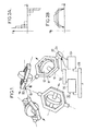
- Figure 1 shows a cluster of four gyrodynes 10a, 10b, 10c, 10d identical, each having a router 12 mounted on a gimbal 14 so that it can rotate around an axis 16.
- a motor not shown keeps the router in rotation, generally at constant speed.
- Each gimbal is mounted on the platform of the satellite (not shown) so that it can rotate around a axis 18 orthogonal to axis 16.
- Axes 18 have orientations different. In the case shown, they occupy the edges of a regular top pyramid 20.
- Each of the universal joints is provided with a motor 22, of which only one is shown, allowing it to rotate around axis 18 respective.
- An angular sensor 24 gives information on the orientation of the gimbal and therefore of the plane of the wheel 12.
- a control system of attitude which can be of a known type. It has an organ 26 for calculating and controlling the motor 22 which receives instructions orientation of a ground-contact transceiver 28 and signals 30 coming from sensors not shown, such as star and terrestrial horizon sensors, etc. This body controls power circuits 32 supplying the motors.
- This system has usually a relatively long time constant, from a few seconds to several tens of seconds.
- the device also includes control means additional 34 in which final positions to be given to gyrodynes gimbals are downloaded to cause a satellite reorientation maneuver. As indicated above, this final position of all the gyrodynes is evaluated based on the assumption that the reconfiguration will be completed before the attitude control system intervenes to cancel the difference between the actual attitude and the attitude of satellite setpoint in an inertial frame.
- the reconfiguration of the cluster is carried out by reorientation almost instantaneous and independent of the router axes, and not by step-by-step tracking of a predetermined continuous path.
- the initial configuration is non-singular and the final configuration is calculated to be non-singular also.
- the intermediate configurations are so transient that an unlikely loss of rank of the Jacobian goes virtually unnoticed by the attitude control system 26.
- the maximum required angular momentum capacity of the cluster to cause the global angular momentum exchange is up twice less than in the case of the low torque represented by a line in dashed lines.
- the angular momentum capacity is an essential factor in sizing the cluster (mass, dimensions and speed of rotation of the routers), while the Torque capacity of a gyrodyne is only limited by speed maximum rotation of the gimbal motor.
- a position setpoint is sent in a loop open to each engine at the start of each maneuver.
- the position control uses an angle encoder and redirect the gimbal as quickly as possible; the only limit is the band control over gimbal motors and their speed maximum.
- the internal angular momentum is reoriented almost instantaneously compared to the response times of the servo attitude control.
- the control system attitude can be disabled during reconfiguration or its torque control limited to a very low value lower than the capacity of gyrodynes. For that, we can use saturation or filtering techniques.
- Engines gimbals can be of the step type. This removes the servo loop in position, since the stepper motor is directly controlled in position. Fine control of microperturbations and depointings can then be ensured not not by small reorientations of the cardan axes, but by the acceleration or deceleration of the inertia spinners, the system akin then to an unsteady shower of wheels of reaction.
- the satellite is animated by the good speed around the chosen axis, with uncertainties on the inertias and alignments closely.
- the attitude control system can compensate for these errors without difficulty by a local guidance law classic of the bunch. Even after several maneuvers, the excursions of the cardan positions around the configuration of instructions remain limited and the cluster can be brought back canonical configuration during desaturation phases in period Eve.
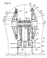
- the gyrodyne then comprises a base 10 which defines, with a waterproof envelope 12, a volume in which is placed the entire actuator. On the base is fixed a tilting mechanism having a stator part 14 and a rotor part which constitutes a support 16.
- the part stator 14 is constituted by a sleeve in which are guiding means (ball bearing by example) 18 spaced from each other so as to give a precise orientation to a tilt axis 20 around which turns a tube 22 belonging to the support.
- the stator and rotor parts also include components of an electronically commutated torque motor 24, having permanent magnets on the rotor part.
- the passage of electric current between the parts rotor and stator can be performed by rotary connectors 26 with ring and brushes, shown in number three in the figure.
- the angular position of the support or rotor part is given at all times by an encoder 38 having a part rigidly fixed to the stator part 14 and a connected rotor to the tube 22 by an elastic coupling 40.
- This arrangement allows the diameter of the 30 bearings so as to ensure the best compromise possible between mechanical strength during launch and after a long lifetime in orbit, a viscous couple acceptable resistive and a natural bending frequency of the tree out of the parasitic frequency range susceptible to be applied.
- the ball bearings can be fitted with baffles that prevent locally deposited oil from escapes.
- a drive motor for the router comprises, in the case presented in the figure, a motor torque 44 brushless and ironless, usually switching electronic, whose torque compensates for dissipations of energy by friction. It can generally include a passive annular rotor belonging to the periphery of one of flanges 36 and a winding 48 supplied via rotary connectors 26 and fixed to a parallel rim 58 to the flange and secured to the socket 28.
- the electronics 50 motor speed control and regulation 44 can be placed on one or more printed circuit boards inside the rim 58 parallel to the flange which is equipped with the motor, and which can be given a shape mushroom.
- the speed of rotation is measured by a tachometer 52 having a crown 54 fixed to the other flange 36 and a active part 56 belonging to a second rim 58, similar to the one that supports the winding 48.
- the second rim may contain a signal processing card 60 provided by the tachometer, connected to the outside by one of the connectors turning 26.
- the tachometer 52 is advantageously contactless.
- a tachometer having couplers opto-electronics.
- Each coupler comprises for example at at least one light emitting diode and at least one phototransistor carried by the rim, cooperating with the annular crown 54 which has alternating transmission zones and occultation of a beam between the light-emitting diode and the phototransistor.
- the means for supplying the motors 44 from a external electrical source not shown may be mounted on a card 62 placed around the base of the stator part 14.
- the means of supplying the motor of tilt 24 can be placed on another card 64.
- External connections, not shown, allow switching to be controlled from a circuit outside.
Priority Applications (1)
| Application Number | Priority Date | Filing Date | Title |
|---|---|---|---|
| EP04076876A EP1484247B1 (de) | 1998-11-19 | 1999-07-21 | Gyroskopischer Stellantrieb, insbesondere für die Lageregelung eines Satelliten |
Applications Claiming Priority (2)
| Application Number | Priority Date | Filing Date | Title |
|---|---|---|---|
| FR9814548A FR2786283B1 (fr) | 1998-11-19 | 1998-11-19 | Procede et dispositif de pilotage de l'attitude d'un satellite |
| FR9814548 | 1998-11-19 |
Related Child Applications (1)
| Application Number | Title | Priority Date | Filing Date |
|---|---|---|---|
| EP04076876A Division EP1484247B1 (de) | 1998-11-19 | 1999-07-21 | Gyroskopischer Stellantrieb, insbesondere für die Lageregelung eines Satelliten |
Publications (2)
| Publication Number | Publication Date |
|---|---|
| EP1002716A1 true EP1002716A1 (de) | 2000-05-24 |
| EP1002716B1 EP1002716B1 (de) | 2005-08-24 |
Family
ID=9532924
Family Applications (2)
| Application Number | Title | Priority Date | Filing Date |
|---|---|---|---|
| EP04076876A Expired - Lifetime EP1484247B1 (de) | 1998-11-19 | 1999-07-21 | Gyroskopischer Stellantrieb, insbesondere für die Lageregelung eines Satelliten |
| EP99401843A Expired - Lifetime EP1002716B1 (de) | 1998-11-19 | 1999-07-21 | Methode und Vorrichtung zur Lageregelung eines Satelliten |
Family Applications Before (1)
| Application Number | Title | Priority Date | Filing Date |
|---|---|---|---|
| EP04076876A Expired - Lifetime EP1484247B1 (de) | 1998-11-19 | 1999-07-21 | Gyroskopischer Stellantrieb, insbesondere für die Lageregelung eines Satelliten |
Country Status (5)
| Country | Link |
|---|---|
| US (1) | US6305647B1 (de) |
| EP (2) | EP1484247B1 (de) |
| DE (2) | DE69926854T2 (de) |
| ES (2) | ES2247767T3 (de) |
| FR (1) | FR2786283B1 (de) |
Cited By (6)
| Publication number | Priority date | Publication date | Assignee | Title |
|---|---|---|---|---|
| FR2850948A1 (fr) | 2003-02-07 | 2004-08-13 | Astrium Sas | Dispositif de pilotage de l'attitude d'un satellite par actionneurs gyroscopiques |
| EP1484247A1 (de) | 1998-11-19 | 2004-12-08 | Eads Astrium Sas | Gyroskopischer Stellantrieb, insbesondere für die Lageregelung eines Satelliten |
| WO2006137843A3 (en) * | 2004-08-26 | 2007-03-22 | Honeywell Int Inc | Quantized control-moment gyroscope array |
| EP1793297A2 (de) | 2005-11-30 | 2007-06-06 | Honeywell Inc. | Verfahren und System zur Steuerung von kollinearen Steuermomentkreiselsätzen |
| EP2263937A1 (de) * | 2009-06-18 | 2010-12-22 | Honeywell International Inc. | Gyroskop auf Grundlage von Impulsregelungssystemen in kleinen Satelliten |
| FR2981050A1 (fr) * | 2011-10-07 | 2013-04-12 | Larminat Philippe De | Commande d'actionneur gyroscopique par formulation directe, pour pilotage d'attitude de satellite agile |
Families Citing this family (40)
| Publication number | Priority date | Publication date | Assignee | Title |
|---|---|---|---|---|
| US6454218B1 (en) * | 2000-02-28 | 2002-09-24 | Quoin International, Inc. | Integrated system for providing 3-axis attitude-control, energy-storage, and electrical power |
| FR2819597B1 (fr) | 2001-01-15 | 2003-04-11 | Cit Alcatel | Procede de guidage d'un systeme d'actionneurs gyrospcopiques |
| US6729580B2 (en) * | 2001-04-05 | 2004-05-04 | Northrop Grumman Corporation | Method and system for directing an object using gyroscopes |
| FR2826470B1 (fr) * | 2001-06-26 | 2003-09-19 | Astrium Sas | Procede et dispositif de pilotage de l'attitude et de guidage d'un satellite par grappe de gyrodynes |
| US6691955B2 (en) * | 2001-11-27 | 2004-02-17 | Space Systems/Loral | Spacecraft having a momentum wheel configuration that prevents zero wheel speeds |
| FR2837580B1 (fr) | 2002-03-21 | 2005-06-03 | Astrium Sas | Actionneur gyroscopique de pilotage de l'attitude d'un vehicule spatial |
| US6682019B2 (en) * | 2002-04-04 | 2004-01-27 | Honeywell International Inc. | Minimum energy wheel configurations for energy storage and attitude control |
| JP3970724B2 (ja) * | 2002-08-30 | 2007-09-05 | Nec東芝スペースシステム株式会社 | 飛翔体の姿勢変更制御装置及び姿勢変更制御方法 |
| US7152495B2 (en) * | 2002-12-19 | 2006-12-26 | Honeywell International, Inc. | System and method for adaptive cancellation of disturbances |
| US6758444B1 (en) * | 2002-12-30 | 2004-07-06 | Honeywell International Inc. | Momentum control system and method |
| US6779759B1 (en) * | 2003-03-28 | 2004-08-24 | Honeywell International, Inc. | Integrated power and attitude control system and method |
| FR2858294A1 (fr) * | 2003-07-28 | 2005-02-04 | Eads Astrium Sas | Roue d'inertie pour vehicule |
| US7561947B2 (en) * | 2003-10-06 | 2009-07-14 | Honeywell International Inc. | Dynamic CMG array and method |
| FR2861690B1 (fr) | 2003-11-04 | 2006-04-07 | Eads Astrium Sas | Controle d'attitude de satellites en particulier agiles a nombre reduit de gyrodynes |
| US7185855B2 (en) * | 2004-04-30 | 2007-03-06 | Honeywell International, Inc. | Method and system for steering a momentum control system |
| KR100552583B1 (ko) | 2004-11-16 | 2006-02-15 | 한국과학기술원 | 특이점 문제를 개선한 제어 모멘트 자이로스코프 및 그구동 방법 |
| GB0606885D0 (en) * | 2006-04-05 | 2006-05-17 | Suisse Electronique Microtech | Torquer apparatus |
| KR100778098B1 (ko) | 2006-07-26 | 2007-11-22 | 한국항공우주연구원 | 인공위성 3축 자세제어용 제어 모멘트 자이로 클러스터 |
| US7805226B2 (en) * | 2006-09-29 | 2010-09-28 | Honeywell International Inc. | Hierarchical strategy for singularity avoidance in arrays of control moment gyroscopes |
| FR2907423B1 (fr) * | 2006-10-23 | 2009-07-03 | Astrium Sas Soc Par Actions Si | Gyrodyne et son dispositif de montage |
| GB2445569A (en) * | 2007-01-12 | 2008-07-16 | Duncan James Harrison | Gyro-coupling torque converter |
| US20090039202A1 (en) * | 2007-02-07 | 2009-02-12 | Keita Ogo | Attitude Change Control Method, Attitude Change Control System, Attitude Change Control Program and Program Recording Medium |
| JP4463287B2 (ja) * | 2007-02-07 | 2010-05-19 | Nec東芝スペースシステム株式会社 | 姿勢変更制御方法、姿勢変更制御システム、姿勢変更制御プログラムおよびプログラム記録媒体 |
| US7997157B2 (en) * | 2008-02-11 | 2011-08-16 | Honeywell International Inc. | Control moment gyroscope |
| US8127631B2 (en) * | 2008-09-17 | 2012-03-06 | Honeywell International Inc. | Rotor assembly including strain relief feature |
| US8688296B2 (en) * | 2008-11-17 | 2014-04-01 | David A. Bailey | Method for maximum data collection with a control moment gyroscope controlled satellite |
| US8209070B2 (en) * | 2008-12-17 | 2012-06-26 | Honeywell International Inc. | Methods and systems for efficiently orienting an agile vehicle using a gyroscope array |
| WO2010135421A2 (en) | 2009-05-19 | 2010-11-25 | University Of Florida Research Foundation, Inc. | Attitude control system for small satellites |
| US9061775B2 (en) * | 2012-06-22 | 2015-06-23 | Isaac M. Ross | Method and apparatus for spacecraft attitude control using polynomial interpolation |
| US8880246B1 (en) * | 2012-08-22 | 2014-11-04 | United States Of America As Represented By The Secretary Of The Navy | Method and apparatus for determining spacecraft maneuvers |
| US9849785B1 (en) * | 2012-12-10 | 2017-12-26 | The United States Of America, As Represented By The Secretary Of The Navy | Method and apparatus for state space trajectory control of uncertain dynamical systems |
| CN104699107B (zh) * | 2015-02-05 | 2017-10-13 | 北京理工大学 | 一种控制力矩陀螺群的桁架包络结构的搭建方法 |
| US10114382B2 (en) * | 2016-05-10 | 2018-10-30 | Sikorsky Aircraft Corporation | Flexible command model for aircraft control |
| EP3511253A4 (de) * | 2016-09-09 | 2019-09-11 | Mitsubishi Electric Corporation | Positionssteuerungsvorrichtung, positionssteuerungssystem, bodenstation, künstlicher satellit, verfahren zur steuerung der position und programm |
| CN106553771A (zh) * | 2016-10-21 | 2017-04-05 | 上海卫星工程研究所 | 适用于五棱锥构形布局的sgcmg一体化支撑装置 |
| FR3074685B1 (fr) | 2017-12-12 | 2019-11-22 | Societe D'exploitation De Produits Pour Les Industries Chimiques Seppic | Nouveaux polyol polyrhamnosides, procede pour leur preparation et composition cosmetiques et/ou pharmaceutiques en comprenant |
| FR3074686B1 (fr) | 2017-12-12 | 2019-11-15 | Societe D'exploitation De Produits Pour Les Industries Chimiques Seppic | Nouveaux glyceryl polyrhamnosides, procede pour leur preparation et composition cosmetiques et/ou pharmaceutiques en comprenant |
| CN108146659A (zh) * | 2018-02-08 | 2018-06-12 | 黄君 | 卫星姿态控制磁力矩、卫星姿态控制系统及卫星 |
| CN111099040B (zh) * | 2019-10-18 | 2021-10-29 | 上海航天控制技术研究所 | 一种基于控制力矩陀螺群控制的系统极性确定方法 |
| CN113917958B (zh) * | 2021-08-31 | 2023-05-09 | 北京控制工程研究所 | 一种三浮陀螺单机在轨自主管理与控制方法 |
Citations (3)
| Publication number | Priority date | Publication date | Assignee | Title |
|---|---|---|---|---|
| US4573651A (en) * | 1983-12-19 | 1986-03-04 | Stanton Austin N | Torque orientation device |
| US5441222A (en) * | 1993-04-26 | 1995-08-15 | Hughes Aircraft Company | Attitude control of spinning spacecraft |
| US5692707A (en) * | 1995-05-15 | 1997-12-02 | Hughes Aircraft Company | Universal spacecraft attitude steering control system |
Family Cites Families (13)
| Publication number | Priority date | Publication date | Assignee | Title |
|---|---|---|---|---|
| US3452948A (en) * | 1967-01-03 | 1969-07-01 | Garrett Corp | System and method for free body stabilization and orientation |
| US3603161A (en) * | 1969-09-04 | 1971-09-07 | Bodenseewerk Geraetetech | Gyroscope with collectorless dc motor |
| US3741500A (en) * | 1971-04-21 | 1973-06-26 | Sperry Rand Corp | A cmg fine attitude control system |
| FR2384174A1 (fr) * | 1977-03-15 | 1978-10-13 | Aerospatiale | Roue d'inertie |
| US4375878A (en) * | 1980-10-28 | 1983-03-08 | Lockheed Missiles & Space Company, Inc. | Space satellite with agile payload orientation system |
| JPH01226496A (ja) | 1988-03-07 | 1989-09-11 | Toshiba Corp | 宇宙航行体の姿勢制御装置 |
| US5256942A (en) | 1992-05-07 | 1993-10-26 | Wood Ross C | Stabilization system for a freely rotatable platform |
| WO1994010036A1 (de) * | 1992-10-27 | 1994-05-11 | Teldix Gmbh | Einrichtung zum schwenken eines flugkörpers, mit zwei kreiseln |
| US5386738A (en) * | 1992-12-22 | 1995-02-07 | Honeywell Inc. | Direct torque control moment gyroscope |
| US5681012A (en) * | 1995-01-05 | 1997-10-28 | Hughes Electronics | Spacecraft control with skewed control moment gyros |
| US6131056A (en) * | 1998-03-16 | 2000-10-10 | Honeywell International Inc. | Continuous attitude control that avoids CMG array singularities |
| US6039290A (en) * | 1998-03-16 | 2000-03-21 | Honeywell Inc. | Robust singularity avoidance in satellite attitude control |
| FR2786283B1 (fr) | 1998-11-19 | 2001-01-26 | Matra Marconi Space France | Procede et dispositif de pilotage de l'attitude d'un satellite |
-
1998
- 1998-11-19 FR FR9814548A patent/FR2786283B1/fr not_active Expired - Lifetime
-
1999
- 1999-07-21 DE DE69926854T patent/DE69926854T2/de not_active Expired - Lifetime
- 1999-07-21 EP EP04076876A patent/EP1484247B1/de not_active Expired - Lifetime
- 1999-07-21 DE DE69942590T patent/DE69942590D1/de not_active Expired - Lifetime
- 1999-07-21 ES ES99401843T patent/ES2247767T3/es not_active Expired - Lifetime
- 1999-07-21 EP EP99401843A patent/EP1002716B1/de not_active Expired - Lifetime
- 1999-07-21 ES ES04076876T patent/ES2345487T3/es not_active Expired - Lifetime
- 1999-11-19 US US09/443,366 patent/US6305647B1/en not_active Expired - Lifetime
Patent Citations (3)
| Publication number | Priority date | Publication date | Assignee | Title |
|---|---|---|---|---|
| US4573651A (en) * | 1983-12-19 | 1986-03-04 | Stanton Austin N | Torque orientation device |
| US5441222A (en) * | 1993-04-26 | 1995-08-15 | Hughes Aircraft Company | Attitude control of spinning spacecraft |
| US5692707A (en) * | 1995-05-15 | 1997-12-02 | Hughes Aircraft Company | Universal spacecraft attitude steering control system |
Non-Patent Citations (5)
| Title |
|---|
| H.S. OH AND S.R. VADALI: "Feedback Control and Steering Laws for Spacecraft Using single Gimbal Control Moment Gyros", JOURNAL OF THE ASTRONAUTICAL SCIENCES, vol. 39, no. 2, April 1991 (1991-04-01) - June 1991 (1991-06-01), USA, pages 183 - 203, XP002112652 * |
| HARUHISA KUROKAWA: "Constrained Steering Law of Pyramid-Type Control Moment Gyros and Ground Tests", JOURNAL OF GUIDANCE, CONTROL AND DYNAMICS, vol. 20, no. 3, May 1997 (1997-05-01) - June 1997 (1997-06-01), Washington, DC, US, pages 445 - 449, XP002112653 * |
| JOSEPH A. PARADISO: "Global Steering of Single Gimballed Control Moment Gyroscopes Using a Directional Search", JOURNAL OF GUIDANCE, CONTROL AND DYNAMICS, vol. 15, no. 5, September 1992 (1992-09-01) - October 1992 (1992-10-01), Washington, DC, US, pages 1236 - 1244, XP002112654 * |
| JUN'ICHIRO KAWAGUCHI ET AL.: "Closed Loop Momentum Transfer Maneuvers Using Multiwheels", JOURNAL OF GUIDANCE, CONTROL AND DYNAMICS, vol. 18, no. 4, July 1995 (1995-07-01) - August 1995 (1995-08-01), Washington, DC, US, pages 867 - 874, XP000558528 * |
| S. R. VADALI ET AL.: "Suboptimal Command Generation for Control Moment Gyroscopes and Feedback Control of Spacecraft", JOURNAL OF GUIDANCE, CONTROL AND DYNAMICS, vol. 18, no. 6, November 1995 (1995-11-01) - December 1995 (1995-12-01), Washington, DC, US, pages 1350 - 1354, XP000558647 * |
Cited By (10)
| Publication number | Priority date | Publication date | Assignee | Title |
|---|---|---|---|---|
| EP1484247A1 (de) | 1998-11-19 | 2004-12-08 | Eads Astrium Sas | Gyroskopischer Stellantrieb, insbesondere für die Lageregelung eines Satelliten |
| FR2850948A1 (fr) | 2003-02-07 | 2004-08-13 | Astrium Sas | Dispositif de pilotage de l'attitude d'un satellite par actionneurs gyroscopiques |
| WO2004071869A1 (fr) | 2003-02-07 | 2004-08-26 | Eads Astrium Sas | Dispositif de pilotage de l’attitude d’un satellite par actionneurs gyroscopiques |
| WO2006137843A3 (en) * | 2004-08-26 | 2007-03-22 | Honeywell Int Inc | Quantized control-moment gyroscope array |
| US7364120B2 (en) | 2004-08-26 | 2008-04-29 | Honeywell International, Inc. | Quantized control-moment gyroscope array |
| EP1793297A2 (de) | 2005-11-30 | 2007-06-06 | Honeywell Inc. | Verfahren und System zur Steuerung von kollinearen Steuermomentkreiselsätzen |
| EP1793297A3 (de) * | 2005-11-30 | 2008-09-10 | Honeywell Inc. | Verfahren und System zur Steuerung von kollinearen Steuermomentkreiselsätzen |
| US7693619B2 (en) | 2005-11-30 | 2010-04-06 | Honeywell International Inc. | Method and system for controlling sets of collinear control moment gyroscopes with offset determination without attitude trajectory of spacecraft |
| EP2263937A1 (de) * | 2009-06-18 | 2010-12-22 | Honeywell International Inc. | Gyroskop auf Grundlage von Impulsregelungssystemen in kleinen Satelliten |
| FR2981050A1 (fr) * | 2011-10-07 | 2013-04-12 | Larminat Philippe De | Commande d'actionneur gyroscopique par formulation directe, pour pilotage d'attitude de satellite agile |
Also Published As
| Publication number | Publication date |
|---|---|
| DE69942590D1 (de) | 2010-08-26 |
| EP1002716B1 (de) | 2005-08-24 |
| US6305647B1 (en) | 2001-10-23 |
| DE69926854T2 (de) | 2006-06-29 |
| DE69926854D1 (de) | 2005-09-29 |
| ES2345487T3 (es) | 2010-09-24 |
| FR2786283B1 (fr) | 2001-01-26 |
| EP1484247A1 (de) | 2004-12-08 |
| EP1484247B1 (de) | 2010-07-14 |
| ES2247767T3 (es) | 2006-03-01 |
| FR2786283A1 (fr) | 2000-05-26 |
Similar Documents
| Publication | Publication Date | Title |
|---|---|---|
| EP1002716B1 (de) | Methode und Vorrichtung zur Lageregelung eines Satelliten | |
| EP0435708B1 (de) | Verfahren zur Steuerung der Neigung eines Satelliten bezüglich der Roll- und der Gierachse | |
| EP1680648B1 (de) | Verfahren zur steuerung der lage von satelliten, insbesondere von agilen satelliten mit einer verringerten anzahl von steuermomentkreisel | |
| CA2192050C (fr) | Procede de commande d'attitude d'un satellite en orbite basse, a acquisition solaire | |
| EP3248079B1 (de) | Verfahren und vorrichtung zur steuerung der stellung eines raumfahrzeugs | |
| FR2927312A1 (fr) | Dispositif d'actionneur pour varier l'attitude d'un engin spatial | |
| EP0076179A1 (de) | Verfahren zur Ausrichtung der Rollachse eines Satelliten mit einer gewünschten Richtung | |
| EP3201091B1 (de) | Verfahren zur überwachung der lage eines satelliten in überlebensmodus, angepasste satellit und verfahren zur fernsteuerung solch eines satelliten | |
| FR3013685A1 (fr) | Procede et dispositif de commande d'une phase d'acquisition du soleil par un engin spatial | |
| EP0381574B1 (de) | Gegenrotationsmechanisches Stabilisierungssystem mit eingefügten Rotoren | |
| EP1067446B1 (de) | Verfahren und Vorrichtung zur Lageregelung eines Satelliten | |
| CA1267949A (fr) | Procedure de repointage rapide des satellites a pointage terrestre, et notamment des satellites geostationnaires de telecommunication a stabilisation par volant d'inertie | |
| EP2552782B1 (de) | Steurungsverfahren für ein fluglagenkontrollsystem und fluglagensteuersystem eines raumfahrzeuges | |
| EP0381575B1 (de) | Mechanisches Stabilisierungssystem mit Gegendrehung und einzigem Motor | |
| EP0381573B1 (de) | Gegenrotationsmechanisches Stabilisierungssystem mit getrennten Rotoren | |
| WO2009065818A1 (fr) | Actionneur a transfert de moment cinetique pour le controle d'attitude d'un engin spatial | |
| EP0796786A1 (de) | Verfahren und Vorrichtung für schnelle Betätigung von Nutzlasten an Bord einer Raumplattform | |
| EP1590243A1 (de) | Vorrichtung zur steuerung der lage eines satelliten mittelsgyroskopischer stellantriebe | |
| EP1223104B1 (de) | Leitverfahren für einen Momentregelungsgyroskop | |
| FR2773775A1 (fr) | Actionneur gyroscopique | |
| EP1312997B1 (de) | Steuerungsverfahren zur Lageregelung und Stabilisierung eines Satelliten in niedriger Umlaufbahn, durch Kopplung mit dem Erdmagnetfeld | |
| FR2815730A1 (fr) | Procede de commande d'attitude et de stabilisation d'un satellite en orbite basse, par couplage avec le champ magnetique terrestre |
Legal Events
| Date | Code | Title | Description |
|---|---|---|---|
| PUAI | Public reference made under article 153(3) epc to a published international application that has entered the european phase |
Free format text: ORIGINAL CODE: 0009012 |
|
| AK | Designated contracting states |
Kind code of ref document: A1 Designated state(s): BE DE ES GB IT SE |
|
| AX | Request for extension of the european patent |
Free format text: AL;LT;LV;MK;RO;SI |
|
| 17P | Request for examination filed |
Effective date: 20000706 |
|
| RAP1 | Party data changed (applicant data changed or rights of an application transferred) |
Owner name: ASTRIUM SAS |
|
| AKX | Designation fees paid |
Free format text: BE DE ES GB IT SE |
|
| 17Q | First examination report despatched |
Effective date: 20030422 |
|
| RAP1 | Party data changed (applicant data changed or rights of an application transferred) |
Owner name: EADS ASTRIUM SAS |
|
| GRAP | Despatch of communication of intention to grant a patent |
Free format text: ORIGINAL CODE: EPIDOSNIGR1 |
|
| GRAS | Grant fee paid |
Free format text: ORIGINAL CODE: EPIDOSNIGR3 |
|
| GRAA | (expected) grant |
Free format text: ORIGINAL CODE: 0009210 |
|
| AK | Designated contracting states |
Kind code of ref document: B1 Designated state(s): BE DE ES GB IT SE |
|
| REG | Reference to a national code |
Ref country code: GB Ref legal event code: FG4D Free format text: NOT ENGLISH |
|
| REF | Corresponds to: |
Ref document number: 69926854 Country of ref document: DE Date of ref document: 20050929 Kind code of ref document: P |
|
| RAP2 | Party data changed (patent owner data changed or rights of a patent transferred) |
Owner name: EADS ASTRIUM SAS |
|
| GBT | Gb: translation of ep patent filed (gb section 77(6)(a)/1977) |
Effective date: 20051104 |
|
| REG | Reference to a national code |
Ref country code: SE Ref legal event code: TRGR |
|
| REG | Reference to a national code |
Ref country code: ES Ref legal event code: FG2A Ref document number: 2247767 Country of ref document: ES Kind code of ref document: T3 |
|
| PLBE | No opposition filed within time limit |
Free format text: ORIGINAL CODE: 0009261 |
|
| STAA | Information on the status of an ep patent application or granted ep patent |
Free format text: STATUS: NO OPPOSITION FILED WITHIN TIME LIMIT |
|
| 26N | No opposition filed |
Effective date: 20060526 |
|
| PGFP | Annual fee paid to national office [announced via postgrant information from national office to epo] |
Ref country code: ES Payment date: 20180830 Year of fee payment: 20 Ref country code: IT Payment date: 20180712 Year of fee payment: 20 Ref country code: DE Payment date: 20180710 Year of fee payment: 20 |
|
| PGFP | Annual fee paid to national office [announced via postgrant information from national office to epo] |
Ref country code: GB Payment date: 20180718 Year of fee payment: 20 Ref country code: BE Payment date: 20180725 Year of fee payment: 20 Ref country code: SE Payment date: 20180716 Year of fee payment: 20 |
|
| REG | Reference to a national code |
Ref country code: DE Ref legal event code: R071 Ref document number: 69926854 Country of ref document: DE |
|
| REG | Reference to a national code |
Ref country code: GB Ref legal event code: PE20 Expiry date: 20190720 |
|
| REG | Reference to a national code |
Ref country code: BE Ref legal event code: MK Effective date: 20190721 |
|
| PG25 | Lapsed in a contracting state [announced via postgrant information from national office to epo] |
Ref country code: GB Free format text: LAPSE BECAUSE OF EXPIRATION OF PROTECTION Effective date: 20190720 |
|
| REG | Reference to a national code |
Ref country code: ES Ref legal event code: FD2A Effective date: 20200902 |
|
| PG25 | Lapsed in a contracting state [announced via postgrant information from national office to epo] |
Ref country code: ES Free format text: LAPSE BECAUSE OF EXPIRATION OF PROTECTION Effective date: 20190722 |