US7805226B2 - Hierarchical strategy for singularity avoidance in arrays of control moment gyroscopes - Google Patents
Hierarchical strategy for singularity avoidance in arrays of control moment gyroscopes Download PDFInfo
- Publication number
- US7805226B2 US7805226B2 US11/540,452 US54045206A US7805226B2 US 7805226 B2 US7805226 B2 US 7805226B2 US 54045206 A US54045206 A US 54045206A US 7805226 B2 US7805226 B2 US 7805226B2
- Authority
- US
- United States
- Prior art keywords
- null space
- momentum
- cmgs
- mandatory
- angle
- Prior art date
- Legal status (The legal status is an assumption and is not a legal conclusion. Google has not performed a legal analysis and makes no representation as to the accuracy of the status listed.)
- Active, expires
Links
- 238000003491 array Methods 0.000 title description 3
- 239000011159 matrix material Substances 0.000 claims abstract description 24
- 230000003190 augmentative effect Effects 0.000 claims abstract description 6
- 239000013598 vector Substances 0.000 claims description 55
- 230000033001 locomotion Effects 0.000 claims description 28
- 238000000034 method Methods 0.000 claims description 13
- 230000035515 penetration Effects 0.000 claims description 9
- 238000013459 approach Methods 0.000 description 8
- 230000008859 change Effects 0.000 description 3
- 230000009471 action Effects 0.000 description 2
- 238000004519 manufacturing process Methods 0.000 description 2
- 230000008569 process Effects 0.000 description 2
- 230000009467 reduction Effects 0.000 description 2
- 230000004044 response Effects 0.000 description 2
- 238000000354 decomposition reaction Methods 0.000 description 1
- 238000010586 diagram Methods 0.000 description 1
- 230000000694 effects Effects 0.000 description 1
- 238000013507 mapping Methods 0.000 description 1
Images


Classifications
-
- B—PERFORMING OPERATIONS; TRANSPORTING
- B64—AIRCRAFT; AVIATION; COSMONAUTICS
- B64G—COSMONAUTICS; VEHICLES OR EQUIPMENT THEREFOR
- B64G1/00—Cosmonautic vehicles
- B64G1/22—Parts of, or equipment specially adapted for fitting in or to, cosmonautic vehicles
- B64G1/24—Guiding or controlling apparatus, e.g. for attitude control
- B64G1/28—Guiding or controlling apparatus, e.g. for attitude control using inertia or gyro effect
- B64G1/286—Guiding or controlling apparatus, e.g. for attitude control using inertia or gyro effect using control momentum gyroscopes (CMGs)
-
- B—PERFORMING OPERATIONS; TRANSPORTING
- B64—AIRCRAFT; AVIATION; COSMONAUTICS
- B64G—COSMONAUTICS; VEHICLES OR EQUIPMENT THEREFOR
- B64G1/00—Cosmonautic vehicles
- B64G1/22—Parts of, or equipment specially adapted for fitting in or to, cosmonautic vehicles
- B64G1/24—Guiding or controlling apparatus, e.g. for attitude control
- B64G1/244—Spacecraft control systems
- B64G1/245—Attitude control algorithms for spacecraft attitude control
-
- Y—GENERAL TAGGING OF NEW TECHNOLOGICAL DEVELOPMENTS; GENERAL TAGGING OF CROSS-SECTIONAL TECHNOLOGIES SPANNING OVER SEVERAL SECTIONS OF THE IPC; TECHNICAL SUBJECTS COVERED BY FORMER USPC CROSS-REFERENCE ART COLLECTIONS [XRACs] AND DIGESTS
- Y10—TECHNICAL SUBJECTS COVERED BY FORMER USPC
- Y10T—TECHNICAL SUBJECTS COVERED BY FORMER US CLASSIFICATION
- Y10T74/00—Machine element or mechanism
- Y10T74/12—Gyroscopes
- Y10T74/1221—Multiple gyroscopes
-
- Y—GENERAL TAGGING OF NEW TECHNOLOGICAL DEVELOPMENTS; GENERAL TAGGING OF CROSS-SECTIONAL TECHNOLOGIES SPANNING OVER SEVERAL SECTIONS OF THE IPC; TECHNICAL SUBJECTS COVERED BY FORMER USPC CROSS-REFERENCE ART COLLECTIONS [XRACs] AND DIGESTS
- Y10—TECHNICAL SUBJECTS COVERED BY FORMER USPC
- Y10T—TECHNICAL SUBJECTS COVERED BY FORMER US CLASSIFICATION
- Y10T74/00—Machine element or mechanism
- Y10T74/12—Gyroscopes
- Y10T74/1229—Gyroscope control
Definitions
- This invention relates to the field of spacecraft vehicle control and, more specifically, to a hierarchical strategy for singularity avoidance in arrays of control moment gyroscopes.
- a CMG typically comprises a flywheel with a fixed or variable spin rate mounted to a gimbal assembly.
- the spin axis of the CMG can be tilted by moving the CMG using the gimbal assembly. This motion produces a gyroscopic torque orthogonal to the spin axis and gimbal axis.
- a minimum of three CMGs arranged such that each CMG in the CMG array imparts torque about a linearly independent axis, can be used.
- additional CMGs are provided for redundancy purposes and to help avoid singularities.
- a singularity occurs when the momentum vectors of the CMGs line up such that one or more components of the requested torque can not be provided.
- the CMGs are moved about their gimbal axes in response to a torque command.
- C is a 3 ⁇ n Jacobian matrix
- ⁇ is a n1 ⁇ array of gimbal rates for the n gimbals
- ⁇ is a 3 ⁇ 1 array of torque components to be imparted to the spacecraft.
- a second approach is to limit the CMG array's momentum to a smaller volume within the CMG array's overall momentum envelope.
- the momentum envelope is the momentum provided in all possible combinations of the CMGs in the CMG array. By operating in a subvolume in which no singularities exist, singularities can be avoided.
- this approach wastes potential momentum and results in systems that are larger and heavier than needed.
- a minimum of three CMGs are required.
- a non-symmetrical array of N CMGs each of whose gimbal angle is independently controlled, has N degrees of freedom.
- a minimum of three CMGs are needed to provide a full three degrees of freedom.
- every point in momentum space in the XYZ coordinate system can be reached by one, and only one set of gimbal angles.
- each point in momentum space in the XYZ coordinate system can be mapped to an indefinite number of gimbal angles. This can be used to provide a requested torque while also avoiding singularities.
- null space can be used to avoid singularities
- null motions use gimbal rate that might otherwise be available for torque production. Therefore, the tasks of avoiding singularities and maximizing available torque can be mutually exclusive.
- a method for avoiding singularities in the movement of a set of control moment gyroscopes (CMGs) that includes at least one additional CMG (resulting in null space) includes a hierarchical two-step process. The first step is determining a mandatory null space maneuver to avoid singularities that must be applied even at the expense of torque production. Next, an optional null space maneuver to increase available torque is determined, but applied only to the extent torque allows.
- CMGs control moment gyroscopes
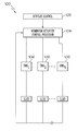
- FIG. 1 is a block diagram illustrating an exemplary CMG control system in accordance with the teachings of the present invention
- FIG. 2 is an exemplary embodiment of an array of CMGs arranged in a “roof” array geometry in accordance with the teachings of the present invention
- FIG. 3 illustrates an exemplary embodiment of momentum vectors of three parallel CMGs in accordance with the teachings of the present invention
- FIG. 4 a illustrates an exemplary embodiment of a configuration of momentum vectors producing a maximum momentum in the X-direction in accordance with the teachings of the present invention
- FIG. 4 b illustrates an exemplary embodiment of a configuration of momentum vectors producing a maximum momentum of 3 h in the Y-direction in accordance with the teachings of the present invention
- FIG. 5 illustrates an exemplary embodiment of a singular CMG alignment in accordance with the teachings of the present invention
- FIGS. 6 a , 6 b and 6 c illustrate different exemplary configurations of momentum vectors that combine to form a net momentum of 1 h in the negative X direction in accordance with the teachings of the present invention
- FIG. 7 illustrates an exemplary embodiment of various ideal momentum vector combinations in accordance with the teachings of the present invention.
- FIG. 8 is a graph illustrating an exemplary embodiment of the available torque in a system of three parallel CMGs under all possible gimbal angle sets in accordance with the teachings of the present invention
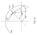
- FIG. 9 illustrates an exemplary set of momentum vectors for three parallel CMGs deviating from an ideal configuration in accordance with the teachings of the present invention
- FIG. 10 is an exemplary embodiment of the extent of null space as viewed from the Hr- ⁇ frame with a limit point in accordance with the teachings of the present invention.
- FIG. 11 is a flowchart illustrating a method for determining mandatory and discretionary CMG movements to avoid singularities and to maximize available torque in accordance with the teachings of the present invention.
- a set of CMGs configured to allow null-space maneuvering is a set of CMGs that has at least one additional CMG above what is required to provide the n-degrees of freedom needed for maneuvering in N-space.
- Four or more CMGs are required in an array designed for maneuvering in three-dimensional space.
- FIG. 1 An exemplary control system 100 for implementing the present invention is illustrated in FIG. 1 .
- the components of the control system 100 are known in the art and can be assembled in different ways using different processors, software, controllers, sensors and the like. Additionally, various computational functionalities that are typically provided by one part of the system can instead be provided by another part or parts.
- the system 100 as shown in FIG. 1 illustrates parts that are pertinent to the discussion of the present invention only and may not include other elements or systems that can be provided in a control system and which are well known.
- the control system 100 includes an attitude control system 102 coupled to a momentum actuator control processor 104 .
- CMGs 106 are coupled to the momentum actuator control processor 104 .
- Associated with each CMG 106 are one or more CMG sensors 108 for providing information concerning the state of the CMG 106 to the control system 100 .
- Control system 100 in one embodiment, is mounted on a spacecraft such as an orbiting satellite.
- Attitude control system 102 controls the positioning of a spacecraft.
- the attitude control system 102 receives data concerning a desired spacecraft maneuver and determines an appropriate torque command to complete the desired maneuver.
- the torque commands can be presented to the momentum actuator control processor 104 .
- the momentum actuator control processor 104 in response to the torque commands, can calculate the gimbal rates necessary to produce the commanded torque.
- the momentum actuator control processor 104 based on the above identified calculations, provides the necessary commands to the CMGs 106 such that the CMG 106 movement produces the commanded torque and, in accordance with the teachings of the present invention, provides the torque while avoiding singularities by using null space maneuvering.
- FIG. 2 illustrates an exemplary embodiment of an array 200 of CMGs 106 arranged in what is known as “roof” array geometry.
- the CMGs 106 are split into a first group 202 and a second group 204 .
- the first group 202 and second group 204 of CMGs 106 are nominally at right angles.
- FIG. 3 illustrates the three momentum vectors, h 1 , h 2 , and h 3 of three parallel CMGs 106 .
- the array of CMGs 106 is shown in an initial zero-momentum state.
- each of the groups of CMGs 106 in either first group 202 or the second group 204 includes three CMGs 106 and, therefore, three degrees of freedom. This provides, for each group, two degrees of freedom in the momentum disk and an additional degree of freedom for null space maneuvering.
- FIG. 4 a illustrates the alignment momentum of each vector, h i , for each CMG 106 to produce a maximum momentum of 3 h in the X-direction.
- the second momentum vector, h 2 , and the third momentum vector, h 3 are rotated to the X-axis.
- FIG. 4 b illustrates a maximum momentum of 3 h in the Y-direction.
- the first momentum vector, h 1 , the second momentum vector, h 2 , and the third momentum vector, h 3 are rotated towards the Y-axis to produce a total momentum of 3 h in the Y-direction.
- the three CMGs 106 can combine to produce a total momentum of 3 h in a desired direction.
- the maximum momentum is 3 h, which is located in a 3 h circle about the origin.
- this condition produces a singularity, but is typically referred to as the “saturation” singularity. To avoid control difficulties that arise as the saturation singularity is approached, a margin between the saturation momentum and the momentum allowed should be provided.
- FIG. 5 Another exemplary embodiment of CMG 106 alignment is illustrated in FIG. 5 , where a command is given to the CMGs 106 to produce a maximum net momentum in the negative X direction (to the left of the origin).
- a command is given to the CMGs 106 to produce a maximum net momentum in the negative X direction (to the left of the origin).
- the CMGs 106 that produce the momentum vectors h 2 and h 3 would be moved in the correct direction, but since
- the controller would deduce that there was no value in moving the CMG 106 corresponding to the momentum vector, h 1 .
- the net momentum of the three CMGs 106 is now only 1 h in magnitude and there is no way to produce any more momentum without producing an error in the Y-axis. Specifically, there is no small change in gimbal angles that can produce a small increase in momentum in the desired direction. This is called an “internal” singularity.
- three parallel CMGs 106 have an internal singularity circle at radius 1 h. Every point on the circle has the potential of being a singular point like the one described above.
- FIG. 6 a , 6 b and 6 c different configurations of the CMGs 106 momentum vectors are illustrated that combine to form a net momentum of 1 h in the negative X direction.
- FIG. 7 illustrates various ideal combinations of momentum vectors 702 . Note that in FIG. 7 , there is a discontinuity at the origin as the radially aligned CMG 106 momentum vector switches from the X to the ⁇ X direction. Thus, it would not be possible to define a simple fixed mapping from momentum space to gimbal space. Instead, null space must be “navigated”.
- FIG. 8 is a graph 800 that illustrates the available torque (in whatever direction that torque is smallest) in a system of three parallel CMGs 106 under all possible gimbal angle sets. All possible gimbal angle sets include the entire null space, not only the “ideal” gimbal angles. As shown in FIG. 8 , the torque available, forms a band from the largest available torque (ideal gimbal angles) to the smallest torque (which goes to zero at singularity).
- the goals of null-space steering can be determined to be (1) encourage the system to stay near the upper end of the band as illustrated in FIG. 8 , and (2) ensure that the system stay above some preset keep out zone in the band.
- the first goal is discretionary in that it should be accomplished with any extra available gimbal rate after the torque commands are met.
- the second goal must be met, even at the expense of limiting the system torque.
- the Jacobian matrix can be defined as:
- a third vector of gimbal rates exists that produces no torque. This is the null space vector. It can be obtained, in one exemplary embodiment, through the use of singular value decomposition.
- ideal gimbal angles are points in null space at which the maximum determinant and available torque occur (as illustrated in conjunction with FIG. 8 ).
- ideal gimbal sets are characterized by one gimbal directed radially outward, and the other two making equal angles from the radial line. The half-angle between these two is directly a function of the radial distance from the origin, and can be shown to follow the relationship:
- Eqn. 5 can be used to determine exactly how far a gimbal must move to arrive at the optimum point.
- the magnitude of H is 0.65, and, from Eqn. 5, the half-angle ⁇ is 80 degrees.
- the CMG 106 whose momentum vector is violating the keep out zone 902 can be determined along with the direction the momentum vector of the CMG 106 must move.
- An angle T can be determined as the angle between a radial line 904 and a momentum vector 906 of the CMG 106 violating the keep out zone 902 .
- the CMG 106 corresponding to the momentum vector 906 is known as the violating CMG.
- FIG. 10 illustrates the extent of null space as viewed in the Hr- ⁇ frame.
- the top of the band 1008 (optimum gimbal angles) is where the value of ⁇ is equal to the value of ⁇ as derived in equation (5).
- the different regions 1010 - 1016 shown correspond to different values of the determinant of the square matrix [CC T ], where the determinant reduces as we move toward 1016 .
- all trajectories in Hr- ⁇ space must pass over this limit point 1002 .
- a line from the first starting point 1004 or second starting point 1006 to the limit point 1002 can be defined such that the Hr- ⁇ trajectory must not go below the line.
- the final step in the process is imposing the gimbal rate calculated above. Since the total gimbal rate commands are the range-space commands (torque commands) plus the null space commands (singularity avoidance commands), the null space action can be selected that produces the desired sum on the violating CMG. The gimbal rates determined are then checked to ensure that none of the three CMGs 106 are being commanded with rates outside their maximum capability. If they are, then the entire net vector must be scaled down. This results in a reduction in torque magnitude, but only the exact amount of reduction necessary to clear the limit point 1002 .
- the limit point 1002 can be adjusted upward to provide greater margin for singularity avoidance or the limit point 1002 can be adjusted downward to provide smaller margin for singularity avoidance. Also, while only one limit point 1002 was shown in FIG. 10 , multiple limit points 1002 can be determined, which then form multiple line segments that define a keepout zone for null space maneuvers to avoid singularities with some predetermined margin.
- null space movements can also be made to make more torque available.
- the different regions 1008 - 1016 correspond to the determinant of the square matrix [CC T ].
- Region 1008 has the greatest determinant value while region 1016 has the lowest determinant value.
- the strategy to improve the overall condition of the CMG array is to make null space maneuvers that result in a larger value for ⁇ , which is equivalent to moving upward on the graph to a region with a larger determinant value.
- step 1104 from the current state of the array,
- the radial momentum vector, Hr, and the unit momentum vector, h i , for each CMG 106 are determined. Also, the violating CMG 106 as discussed previously is determined.
- step 1106 the angle ⁇ is determined. As previously discussed, ⁇ is the angle between the radial line of the optimal CMG 106 alignment and the momentum vector 906 .
- a slope for the maneuver is calculated that clears the boundary that defines the singularity avoidance criteria.
- the boundary represents lines below which the angle ⁇ must not fall when the CMGs 106 are moving to provide torque.
- step 1116 the optimal angle for the present position of the CMG 106 is calculated from:
- the depth of penetration is determined.
- the depth of penetration represents how far the unit vector for the violating CMG 106 is within the keep out zone 902 . This can be calculated by subtracting the optimal angle, ⁇ , from ⁇ .
- discretionary movements are determined.
- discretionary movements for a given momentum magnitude, increases the ⁇ value to improve the overall condition of the system. This increases the torque available in the system but is not sufficient for singularity avoidance.
- the gimbal rate to implement the movement is determined by using the depth of penetration of the momentum vector 906 of the CMG 106 that is in the keep out zone 902 . By reducing the depth of penetration, ⁇ is increased and the overall condition of the system, in terms of available torque, is increased.
- step 1122 secondary gimbal rate commands for each of the gimbals of the CMGs 106 are determined for the discretionary movements as calculated in step 1120 .
- step 1110 the
- ⁇ ⁇ ⁇ H which in an exemplary embodiment, is a 3 ⁇ 2 matrix.
- the null vector is the vector of gimbal rates that produce no torque.
- step 1112 After the slope for the maneuver is determined in step 1108 that clears the boundary, in step 1112 the movements of the CMGs 106 are required to follow the determinant slope. In other words, the slopes calculated in step 1108 are imposed as criteria for null space movement.
- a simple inverse-Jacobian control matrix can be augmented to impose the calculated slope in the Hr- ⁇ plane (the mandatory null space maneuver) to form an augmented control matrix. Note that it is important to recall that the imposed slope action is limited solely to radial motion. When moving tangentially in the disc, Hr does not change, and there should be no motion in the Hr- ⁇ plane. Based on the relationship of equation 6, values k rad and k tang can be computed at each gimbal state that accomplish the goals of this paragraph as follows (polar coordinates).
- step 1124 the primary rates determined in step 1114 are limited without changing the direction of the rate vectors based on overall system characteristics, such as limits on the gimbal rates. Additionally, the secondary rates for discretionary null space movements can be added to the primary rates up to the rate limit for the CMG 106 .
Landscapes
- Engineering & Computer Science (AREA)
- Remote Sensing (AREA)
- Chemical & Material Sciences (AREA)
- Combustion & Propulsion (AREA)
- Radar, Positioning & Navigation (AREA)
- Aviation & Aerospace Engineering (AREA)
- Automation & Control Theory (AREA)
- Control Of Position, Course, Altitude, Or Attitude Of Moving Bodies (AREA)
Abstract
Description
Cω=τ Eqn. 1
ω=C T(CC T)−1τ Eqn. 2
the controller would deduce that there was no value in moving the
and consists of the partial derivatives of the net momentum vector, H, with respect to θ. In the case of three
can be determined and the slope of the line segment from the
Since the quantity Ψ is directly related to the gimbal angle:
the radial momentum vector, Hr, and the unit momentum vector, hi, for each
and the null vector are determined. The inverse of the Jacobian matrix, determined as discussed previously, using the Moore-Penrose pseudo-inverse, is
which in an exemplary embodiment, is a 3×2 matrix. The null vector is the vector of gimbal rates that produce no torque.
Claims (17)
Priority Applications (4)
| Application Number | Priority Date | Filing Date | Title |
|---|---|---|---|
| US11/540,452 US7805226B2 (en) | 2006-09-29 | 2006-09-29 | Hierarchical strategy for singularity avoidance in arrays of control moment gyroscopes |
| EP07117311A EP1908686B1 (en) | 2006-09-29 | 2007-09-26 | Hierarchial strategy for singularity avoidance in arrays of control moment gyroscopes |
| DE602007002242T DE602007002242D1 (en) | 2006-09-29 | 2007-09-26 | Hierarchical strategy for singularity avoidance in a control moment gyro arrangement |
| JP2007254429A JP5241189B2 (en) | 2006-09-29 | 2007-09-28 | Hierarchical concept for avoiding singularities in arrays of control moments and gyroscopes |
Applications Claiming Priority (1)
| Application Number | Priority Date | Filing Date | Title |
|---|---|---|---|
| US11/540,452 US7805226B2 (en) | 2006-09-29 | 2006-09-29 | Hierarchical strategy for singularity avoidance in arrays of control moment gyroscopes |
Publications (2)
| Publication Number | Publication Date |
|---|---|
| US20080105787A1 US20080105787A1 (en) | 2008-05-08 |
| US7805226B2 true US7805226B2 (en) | 2010-09-28 |
Family
ID=38668821
Family Applications (1)
| Application Number | Title | Priority Date | Filing Date |
|---|---|---|---|
| US11/540,452 Active 2029-07-28 US7805226B2 (en) | 2006-09-29 | 2006-09-29 | Hierarchical strategy for singularity avoidance in arrays of control moment gyroscopes |
Country Status (4)
| Country | Link |
|---|---|
| US (1) | US7805226B2 (en) |
| EP (1) | EP1908686B1 (en) |
| JP (1) | JP5241189B2 (en) |
| DE (1) | DE602007002242D1 (en) |
Cited By (4)
| Publication number | Priority date | Publication date | Assignee | Title |
|---|---|---|---|---|
| US8260478B1 (en) * | 2007-07-19 | 2012-09-04 | Rockwell Collins, Inc. | Rotation rate tracking system using GPS harmonic signals |
| US8672062B2 (en) | 2011-05-26 | 2014-03-18 | Gregory C Schroll | Internal means for rotating an object between gravitationally stable states |
| US8880246B1 (en) * | 2012-08-22 | 2014-11-04 | United States Of America As Represented By The Secretary Of The Navy | Method and apparatus for determining spacecraft maneuvers |
| US9567112B1 (en) | 2013-06-27 | 2017-02-14 | The United States Of America, As Represented By The Secretary Of The Navy | Method and apparatus for singularity avoidance for control moment gyroscope (CMG) systems without using null motion |
Families Citing this family (12)
| Publication number | Priority date | Publication date | Assignee | Title |
|---|---|---|---|---|
| TR200706725A2 (en) * | 2007-09-28 | 2009-04-21 | Terz�Akin Mehmet | Spacecraft propulsion system with gyroscope mechanism |
| US8209070B2 (en) * | 2008-12-17 | 2012-06-26 | Honeywell International Inc. | Methods and systems for efficiently orienting an agile vehicle using a gyroscope array |
| WO2011041503A2 (en) * | 2009-10-01 | 2011-04-07 | University Of Florida Research Foundation, Inc. | Split flywheel assembly with attitude jitter minimization |
| US8014911B2 (en) * | 2009-11-03 | 2011-09-06 | Honeywell International Inc. | Methods and systems for imposing a momentum boundary while reorienting an agile vehicle with control moment gyroscopes |
| US20120097798A1 (en) * | 2010-10-25 | 2012-04-26 | Rust Sr John H | Inertial mass suspension |
| US9038958B1 (en) * | 2012-05-29 | 2015-05-26 | United States Of America As Represented By The Secretary Of The Navy | Method and apparatus for contingency guidance of a CMG-actuated spacecraft |
| GB201220653D0 (en) * | 2012-11-16 | 2013-01-02 | Mcculloch Norman L | Improvements in aircraft |
| ITTO20131067A1 (en) | 2013-12-23 | 2015-06-24 | Thales Alenia Space Italia S P A C On Unico Socio | TRIMMING CONTROL SYSTEM FOR AGILE SATELLITE APPLICATIONS |
| CN103940451B (en) * | 2014-04-30 | 2016-08-24 | 北京控制工程研究所 | Redundancy fault location of single redundant gyroscopes method based on the autonomous optimized choice of kernel vector |
| FR3045847B1 (en) * | 2015-12-17 | 2018-01-05 | Centre National D'etudes Spatiales (Cnes) | METHOD FOR CONTROLLING A REDUNDANT SYSTEM |
| CN107894776A (en) * | 2017-11-09 | 2018-04-10 | 酷黑科技(北京)有限公司 | A kind of unmanned plane augmentation control method, apparatus and unmanned plane |
| CN110990943B (en) * | 2019-11-13 | 2023-10-20 | 上海航天控制技术研究所 | Singular point judgment method based on singular geometric meaning of control moment gyro group |
Citations (18)
| Publication number | Priority date | Publication date | Assignee | Title |
|---|---|---|---|---|
| US5269483A (en) * | 1991-07-09 | 1993-12-14 | Aerospatiale Societe Nationale Industrielle | Continuously acting one-way satellite roll-yaw attitude control method and device |
| US5875676A (en) * | 1997-09-02 | 1999-03-02 | Honeywell Inc. | Non colocated rate sensing for control moment gyroscopes |
| US6039290A (en) | 1998-03-16 | 2000-03-21 | Honeywell Inc. | Robust singularity avoidance in satellite attitude control |
| US6047927A (en) * | 1998-03-16 | 2000-04-11 | Honeywell Inc. | Escaping singularities in a satellite attitude control |
| US6128556A (en) * | 1998-03-16 | 2000-10-03 | Honeywell International Inc. | CMG control based on angular momentum to control satellite attitude |
| US6131056A (en) * | 1998-03-16 | 2000-10-10 | Honeywell International Inc. | Continuous attitude control that avoids CMG array singularities |
| US6154691A (en) * | 1997-09-02 | 2000-11-28 | Honeywell International Inc. | Orienting a satellite with controlled momentum gyros |
| US6260805B1 (en) * | 1998-12-29 | 2001-07-17 | Hughes Electronics Corporation | Method of controlling attitude of a momentum biased spacecraft during long-duration thruster firings |
| US6305647B1 (en) * | 1998-11-19 | 2001-10-23 | Matra Marconi Space France | Method and apparatus for steering the attitude of a satellite |
| US6354163B1 (en) | 2000-05-17 | 2002-03-12 | Honeywell International Inc. | Mitigating gimbal induced disturbances in CMG arrays |
| WO2003001311A1 (en) | 2001-06-26 | 2003-01-03 | Eads Astrium Sas | Method and device for controlling satellite attitude and steering using a gyrodyne cluster |
| US6648274B1 (en) * | 2002-04-12 | 2003-11-18 | David A. Bailey | Virtual reaction wheel array |
| US6681649B2 (en) * | 2002-04-03 | 2004-01-27 | Honeywell International Inc. | Inertial control and measurement system |
| WO2004032392A2 (en) | 2002-08-28 | 2004-04-15 | Arizona Board Of Regents | Steering logic for control moment gyro system |
| US20060027708A1 (en) * | 2004-07-23 | 2006-02-09 | Peck Mason A | Method and system for CMG array singularity avoidance |
| WO2006020314A1 (en) | 2004-07-30 | 2006-02-23 | Honeywell International Inc. | Method and system for optimizing torque in a cmg array |
| US20080035797A1 (en) * | 2003-11-04 | 2008-02-14 | Eads Astrium Sas | Method of Controlling the Attitude of Satellites, Particularly Agile Satellites with a Reduced Number of Gyrodynes |
| US7370833B2 (en) * | 2005-10-20 | 2008-05-13 | Honeywell International Inc. | Method and system for determining a singularity free momentum path |
Family Cites Families (1)
| Publication number | Priority date | Publication date | Assignee | Title |
|---|---|---|---|---|
| JP4511390B2 (en) * | 2005-03-01 | 2010-07-28 | 三菱電機株式会社 | Satellite attitude control device |
-
2006
- 2006-09-29 US US11/540,452 patent/US7805226B2/en active Active
-
2007
- 2007-09-26 EP EP07117311A patent/EP1908686B1/en not_active Ceased
- 2007-09-26 DE DE602007002242T patent/DE602007002242D1/en active Active
- 2007-09-28 JP JP2007254429A patent/JP5241189B2/en not_active Expired - Fee Related
Patent Citations (23)
| Publication number | Priority date | Publication date | Assignee | Title |
|---|---|---|---|---|
| US5269483A (en) * | 1991-07-09 | 1993-12-14 | Aerospatiale Societe Nationale Industrielle | Continuously acting one-way satellite roll-yaw attitude control method and device |
| US5875676A (en) * | 1997-09-02 | 1999-03-02 | Honeywell Inc. | Non colocated rate sensing for control moment gyroscopes |
| US6154691A (en) * | 1997-09-02 | 2000-11-28 | Honeywell International Inc. | Orienting a satellite with controlled momentum gyros |
| US6039290A (en) | 1998-03-16 | 2000-03-21 | Honeywell Inc. | Robust singularity avoidance in satellite attitude control |
| US6047927A (en) * | 1998-03-16 | 2000-04-11 | Honeywell Inc. | Escaping singularities in a satellite attitude control |
| US6128556A (en) * | 1998-03-16 | 2000-10-03 | Honeywell International Inc. | CMG control based on angular momentum to control satellite attitude |
| US6131056A (en) * | 1998-03-16 | 2000-10-10 | Honeywell International Inc. | Continuous attitude control that avoids CMG array singularities |
| US6305647B1 (en) * | 1998-11-19 | 2001-10-23 | Matra Marconi Space France | Method and apparatus for steering the attitude of a satellite |
| US6260805B1 (en) * | 1998-12-29 | 2001-07-17 | Hughes Electronics Corporation | Method of controlling attitude of a momentum biased spacecraft during long-duration thruster firings |
| US6354163B1 (en) | 2000-05-17 | 2002-03-12 | Honeywell International Inc. | Mitigating gimbal induced disturbances in CMG arrays |
| WO2003001311A1 (en) | 2001-06-26 | 2003-01-03 | Eads Astrium Sas | Method and device for controlling satellite attitude and steering using a gyrodyne cluster |
| US7171290B2 (en) * | 2001-06-26 | 2007-01-30 | Eads Astrium Sas | Method and device for controlling satellite attitude and steering using a gyrodyne cluster |
| US6681649B2 (en) * | 2002-04-03 | 2004-01-27 | Honeywell International Inc. | Inertial control and measurement system |
| US6648274B1 (en) * | 2002-04-12 | 2003-11-18 | David A. Bailey | Virtual reaction wheel array |
| WO2004032392A2 (en) | 2002-08-28 | 2004-04-15 | Arizona Board Of Regents | Steering logic for control moment gyro system |
| US20040111194A1 (en) * | 2002-08-28 | 2004-06-10 | Bong Wie | Singularity escape/avoidance steering logic for control moment gyro systems |
| US6917862B2 (en) * | 2002-08-28 | 2005-07-12 | Arizona Board Of Regents | Singularity escape/avoidance steering logic for control moment gyro systems |
| US20080035797A1 (en) * | 2003-11-04 | 2008-02-14 | Eads Astrium Sas | Method of Controlling the Attitude of Satellites, Particularly Agile Satellites with a Reduced Number of Gyrodynes |
| US20060027708A1 (en) * | 2004-07-23 | 2006-02-09 | Peck Mason A | Method and system for CMG array singularity avoidance |
| WO2006085996A1 (en) | 2004-07-23 | 2006-08-17 | Honeywell International Inc. | Method and system for cmg array singularity avoidance |
| WO2006020314A1 (en) | 2004-07-30 | 2006-02-23 | Honeywell International Inc. | Method and system for optimizing torque in a cmg array |
| US7014150B2 (en) * | 2004-07-30 | 2006-03-21 | Honeywell International Inc. | Method and system for optimizing torque in a CMG array |
| US7370833B2 (en) * | 2005-10-20 | 2008-05-13 | Honeywell International Inc. | Method and system for determining a singularity free momentum path |
Non-Patent Citations (2)
| Title |
|---|
| European Search Report for Application No. EP 07117311, mailed on Dec. 3, 2007. |
| Kuhns, et al., "A preferred trajectory tracking steering law for spacecraft with redundant CMGs," Proceedings of American Control Conference, 1995, pp. 3111-3115, vol. 5. |
Cited By (4)
| Publication number | Priority date | Publication date | Assignee | Title |
|---|---|---|---|---|
| US8260478B1 (en) * | 2007-07-19 | 2012-09-04 | Rockwell Collins, Inc. | Rotation rate tracking system using GPS harmonic signals |
| US8672062B2 (en) | 2011-05-26 | 2014-03-18 | Gregory C Schroll | Internal means for rotating an object between gravitationally stable states |
| US8880246B1 (en) * | 2012-08-22 | 2014-11-04 | United States Of America As Represented By The Secretary Of The Navy | Method and apparatus for determining spacecraft maneuvers |
| US9567112B1 (en) | 2013-06-27 | 2017-02-14 | The United States Of America, As Represented By The Secretary Of The Navy | Method and apparatus for singularity avoidance for control moment gyroscope (CMG) systems without using null motion |
Also Published As
| Publication number | Publication date |
|---|---|
| US20080105787A1 (en) | 2008-05-08 |
| EP1908686A1 (en) | 2008-04-09 |
| DE602007002242D1 (en) | 2009-10-15 |
| JP5241189B2 (en) | 2013-07-17 |
| JP2008132965A (en) | 2008-06-12 |
| EP1908686B1 (en) | 2009-09-02 |
Similar Documents
| Publication | Publication Date | Title |
|---|---|---|
| US7805226B2 (en) | Hierarchical strategy for singularity avoidance in arrays of control moment gyroscopes | |
| EP1776626B1 (en) | Method and system for cmg array singularity avoidance | |
| JP4307247B2 (en) | Method and apparatus for controlling and steering the attitude of an artificial satellite by a gyrodyne cluster | |
| JP4783366B2 (en) | Method and system for optimizing torque in a CMG array | |
| US6917862B2 (en) | Singularity escape/avoidance steering logic for control moment gyro systems | |
| US7464899B2 (en) | Method and system for determining a singularity free momentum path | |
| JP2004535324A5 (en) | ||
| US7370833B2 (en) | Method and system for determining a singularity free momentum path | |
| US7693619B2 (en) | Method and system for controlling sets of collinear control moment gyroscopes with offset determination without attitude trajectory of spacecraft | |
| McMahon et al. | Simplified singularity avoidance using variable-speed control moment gyroscope null motion | |
| EP2316736B1 (en) | Methods and systems for imposing a momentum boundary while reorienting an agile vehicle with control moment gyroscopes | |
| CN108427429B (en) | Spacecraft visual axis maneuvering control method considering dynamic pointing constraint | |
| Kanzawa et al. | Steering law of control moment gyroscopes for agile attitude maneuvers | |
| EP4032816A1 (en) | Manipulation method suitable for non-redundant sgcmg group | |
| CN113568442A (en) | Satellite alignment control system and method | |
| Yoshimura et al. | Position and attitude control of an underactuated satellite with constant thrust | |
| Avanzini et al. | Optimal rotation sequences in presence of constraints on admissible rotation axes | |
| Liu et al. | Large angle maneuver and high accuracy attitude pointing steering law for variable speed control momentum gyroscopes | |
| Carpenter | Power-optimal steering of a space robotic system driven by control-moment gyroscopes | |
| Ashok et al. | Cmg configuration and steering approach for spacecraft rapid maneuvers | |
| Xie et al. | Spacecraft Attitude Control | |
| JPH0470198B2 (en) |
Legal Events
| Date | Code | Title | Description |
|---|---|---|---|
| AS | Assignment |
Owner name: HONEYWELL INTERNATIONAL, INC., NEW JERSEY Free format text: ASSIGNMENT OF ASSIGNORS INTEREST;ASSIGNORS:HAMILTON, BRIAN J.;UNDERHILL, BRIAN K.;REEL/FRAME:018376/0105 Effective date: 20060928 |
|
| STCF | Information on status: patent grant |
Free format text: PATENTED CASE |
|
| FPAY | Fee payment |
Year of fee payment: 4 |
|
| MAFP | Maintenance fee payment |
Free format text: PAYMENT OF MAINTENANCE FEE, 8TH YEAR, LARGE ENTITY (ORIGINAL EVENT CODE: M1552) Year of fee payment: 8 |
|
| MAFP | Maintenance fee payment |
Free format text: PAYMENT OF MAINTENANCE FEE, 12TH YEAR, LARGE ENTITY (ORIGINAL EVENT CODE: M1553); ENTITY STATUS OF PATENT OWNER: LARGE ENTITY Year of fee payment: 12 |