EP3201091B1 - Verfahren zur überwachung der lage eines satelliten in überlebensmodus, angepasste satellit und verfahren zur fernsteuerung solch eines satelliten - Google Patents
Verfahren zur überwachung der lage eines satelliten in überlebensmodus, angepasste satellit und verfahren zur fernsteuerung solch eines satelliten Download PDFInfo
- Publication number
- EP3201091B1 EP3201091B1 EP15787001.5A EP15787001A EP3201091B1 EP 3201091 B1 EP3201091 B1 EP 3201091B1 EP 15787001 A EP15787001 A EP 15787001A EP 3201091 B1 EP3201091 B1 EP 3201091B1
- Authority
- EP
- European Patent Office
- Prior art keywords
- satellite
- survival
- moment
- magnetic
- magnetic moment
- Prior art date
- Legal status (The legal status is an assumption and is not a legal conclusion. Google has not performed a legal analysis and makes no representation as to the accuracy of the status listed.)
- Active
Links
- 230000004083 survival effect Effects 0.000 title claims description 208
- 238000000034 method Methods 0.000 title claims description 40
- 230000001174 ascending effect Effects 0.000 claims description 23
- 238000013016 damping Methods 0.000 claims description 17
- 238000005259 measurement Methods 0.000 claims description 6
- 238000004590 computer program Methods 0.000 claims description 4
- 230000008878 coupling Effects 0.000 claims 2
- 238000010168 coupling process Methods 0.000 claims 2
- 238000005859 coupling reaction Methods 0.000 claims 2
- 230000000694 effects Effects 0.000 description 6
- 238000000926 separation method Methods 0.000 description 4
- 208000031968 Cadaver Diseases 0.000 description 3
- 230000000306 recurrent effect Effects 0.000 description 3
- 238000012544 monitoring process Methods 0.000 description 2
- 239000013598 vector Substances 0.000 description 2
- 241001644893 Entandrophragma utile Species 0.000 description 1
- 238000012550 audit Methods 0.000 description 1
- 230000015572 biosynthetic process Effects 0.000 description 1
- 238000004891 communication Methods 0.000 description 1
- 238000010586 diagram Methods 0.000 description 1
- 230000005484 gravity Effects 0.000 description 1
- 239000003380 propellant Substances 0.000 description 1
Images


Classifications
-
- B—PERFORMING OPERATIONS; TRANSPORTING
- B64—AIRCRAFT; AVIATION; COSMONAUTICS
- B64G—COSMONAUTICS; VEHICLES OR EQUIPMENT THEREFOR
- B64G1/00—Cosmonautic vehicles
- B64G1/22—Parts of, or equipment specially adapted for fitting in or to, cosmonautic vehicles
- B64G1/42—Arrangements or adaptations of power supply systems
- B64G1/44—Arrangements or adaptations of power supply systems using radiation, e.g. deployable solar arrays
-
- B—PERFORMING OPERATIONS; TRANSPORTING
- B64—AIRCRAFT; AVIATION; COSMONAUTICS
- B64G—COSMONAUTICS; VEHICLES OR EQUIPMENT THEREFOR
- B64G1/00—Cosmonautic vehicles
- B64G1/22—Parts of, or equipment specially adapted for fitting in or to, cosmonautic vehicles
- B64G1/24—Guiding or controlling apparatus, e.g. for attitude control
- B64G1/28—Guiding or controlling apparatus, e.g. for attitude control using inertia or gyro effect
- B64G1/283—Guiding or controlling apparatus, e.g. for attitude control using inertia or gyro effect using reaction wheels
-
- B—PERFORMING OPERATIONS; TRANSPORTING
- B64—AIRCRAFT; AVIATION; COSMONAUTICS
- B64G—COSMONAUTICS; VEHICLES OR EQUIPMENT THEREFOR
- B64G1/00—Cosmonautic vehicles
- B64G1/22—Parts of, or equipment specially adapted for fitting in or to, cosmonautic vehicles
- B64G1/24—Guiding or controlling apparatus, e.g. for attitude control
- B64G1/32—Guiding or controlling apparatus, e.g. for attitude control using earth's magnetic field
Definitions
- the present invention belongs to the field of attitude control of satellites in geocentric orbit, and more particularly to the attitude control of satellites in survival mode in inclined low orbit.
- the term "survival mode” means any attitude control mode of a satellite aiming, from a disturbed initial state, to provide sunshine solar generators which is sufficient to ensure the electric autonomy from a platform of said satellite until it is restored to a state close to the nominal operational conditions.
- the survival mode can be implemented immediately after separation of the launcher and / or, after the mission of the satellite has started, in case of any incident requiring the interruption of the mission (collision with a meteorite, failure of a propellant, etc.).
- a satellite By compass effect, a satellite will naturally orient itself so as to align an internal magnetic moment, formed by means of magneto-couplers, with the local terrestrial magnetic field.
- the angular position of the satellite around the internal magnetic moment can be controlled by means of an internal kinetic moment formed by the flywheels.
- the internal magnetic moment to be formed is determined so as to ensure that a satellite pointing setpoint, in the direction of the Sun, is respected when the internal magnetic moment formed is aligned with the local terrestrial magnetic field.
- the local terrestrial magnetic field in inertial reference, depends on the position of the satellite with respect to the Earth, and therefore varies over time as the satellite moves in its orbit.
- the internal magnetic moment, to be formed in order to respect the satellite's pointing instruction also varies over time as it is measured as the satellite moves on its orbit.
- the internal magnetic moment to be formed is calculated from a terrestrial magnetic field model, context information (notably the position of the satellite with respect to the Earth) and the satellite pointing instruction.
- the patent application FR 2994287 A1 also describes a mode of survival in which magneto-couplers are controlled to control the attitude of the satellite, by compass effect, in order to respect a set point towards the Sun.
- the internal magnetic moment to be formed depends on the local terrestrial magnetic field, and is calculated from context information (direction of the Sun, local terrestrial magnetic field) and from the satellite's pointing instruction.
- a disadvantage of prior art satellite attitude control methods in the prior art lies in the use of a lot of information (context information, pointing instruction), even though it can not generally be guaranteed that all this information will be available in survival mode.
- the context information is not available if the associated sensor or sensors are faulty, and the pointing instruction is not available if it is obtained from a ground station and the associated communication has been interrupted.
- the present invention aims to remedy all or part of the limitations of the solutions of the prior art, including those described above, by providing a survival attitude control attitude that requires a limited number of sensors and actuators .
- the present invention also aims to propose a solution that is compatible with any type of inclined low orbit, particularly non-sun-synchronous orbits, called “drifting" orbits.
- the attitude control method in survival mode is therefore particularly simple and robust, insofar as it implements only inertial actuators, in this case one or more magneto-couplers and one or more flywheels.
- these inertial actuators are used to respectively form a magnetic moment of survival and a kinetic moment of survival.
- the magnetic moment of survival and the kinetic moment of survival, both non-zero are furthermore constant in satellite reference, so that they can be formed independently of any context information.
- the magnetic moment of survival and the kinetic moment of survival are therefore advantageously determined and stored in a memory of the satellite before said satellite enters the survival mode.
- the magnetic moment of survival makes it possible to fix, by compass effect, the attitude of the satellite along two axes with respect to the local terrestrial magnetic field.
- the angular position of said satellite around the magnetic moment of survival that is to say the attitude of said satellite along the third axis, is imposed by the kinetic moment of survival. Indeed, the satellite will naturally orient itself so as to have the kinetic moment of orthogonal survival in the plane of the satellite orbit.
- the attitude of the satellite varies in inertial reference with the variations of the local magnetic field, but is nevertheless controlled along three axes with respect to the local terrestrial magnetic field. It is therefore possible to choose, depending on the orbit of the satellite and the geometry of said satellite (in particular, the arrangement of the solar generator in the satellite reference), a magnetic moment of survival and a kinetic moment of survival that allow ensure that the photosensitive surface of the solar generator is sunny at least once per satellite orbit.
- the magnetic moment of survival and the kinetic moment of survival are predetermined so as to maximize the average sunlight of said photosensitive surface during a satellite orbit.
- the survival mode attitude control method may further comprise one or more of the following characteristics, taken separately or in any technically possible combination.
- the satellite in survival mode (after separation of the launcher and / or after incident occurred during the mission), the satellite can initially be in uncontrolled rotation with a high rotation speed.
- the superposition of a damping magnetic moment (variable over time) at the magnetic moment of survival (constant over time) makes it possible to reduce the speed of rotation of said satellite.
- the magnetic moment actually formed is then a magnetic moment modulated around the magnetic moment of survival.
- the solar generator being arranged along an axis X of the satellite reference, the magnetic survival moment is parallel to the X axis and the kinetic moment of survival is orthogonal to said X axis.
- the solar generator being substantially flat, the kinetic moment of survival forms, with the plane of the solar generator, an angle of non-zero value modulo 90 °, preferably between 10 ° and 80 ° modulo 90 °.
- the ascending node of said orbit being close to midday or midnight and the solar generator being arranged along an axis X of the satellite reference
- the magnetic moment of survival is orthogonal to the axis X and the kinetic moment of survival is parallel to X axis.
- the ascending node of said orbit being close to midday or midnight
- the magnetic moment of survival and the kinetic moment of survival are such that the photosensitive surface of the solar generator is sunny at least twice at during a satellite orbit.
- the orbit of the satellite is substantially polar.
- the present invention relates to a computer program product comprising a set of program code instructions which, when executed by a processor, implement an attitude control method according to one any of the embodiments of the invention.
- the present invention relates to a low inclined orbit satellite comprising a solar generator, a magneto-coupler, a flywheel and a control module of the magneto-coupler and the flywheel.
- the control module comprises a memory in which are memorized a constant non-zero internal magnetic moment setpoint in a satellite reference frame linked to the satellite, called "magnetic survival moment", and a non-zero internal kinetic momentum instruction. constant in said satellite reference, said "kinetic moment of survival”.
- the control module is configured to control, when the satellite is in survival mode, the magneto-coupler and the flywheel so as to simultaneously form the magnetic moment of survival and the kinetic moment of survival during a part of the less of the survival mode.
- the satellite may further comprise one or more of the following characteristics, taken separately or in any technically possible combination.
- the solar generator being arranged along an axis X of the satellite reference, the magnetic survival moment is parallel to the X axis and the kinetic moment of survival is orthogonal to the X axis.
- the solar generator being substantially flat, the kinetic moment of survival forms, with said plane of said solar generator, an angle of non-zero value modulo 90 °, preferably between 10 ° and 80 ° modulo 90 ° .
- the present invention relates to a method for remote control of a satellite whose attitude in survival mode is controlled according to any of the embodiments of the invention.
- the orbit of the satellite being a drift
- the method comprises, when the satellite is not in survival mode, a recurrent step of updating the instructions of magnetic moment of survival and kinetic moment of survival stored in the memory of the control module.
- the satellite being in drifting orbit, it may be impossible to have instructions for magnetic moment of survival and survival kinetic moment that ensure sufficient sunlight sufficient photosensitive surface of the solar generator for all the possible orbits of said satellite.
- the instructions for magnetic moment of survival and kinetic moment of survival are updated recurrently, when the satellite is not in survival mode, in order to better adapt them to the subsequent orbits of the satellite, if this one had to go into survival mode. These instructions are not updated during the survival mode.
- the instructions for magnetic moment of survival and kinetic moment of survival are constant throughout the duration of said survival mode.
- the remote control method may further comprise one or more of the following characteristics, taken individually or in any technically possible combination.
- the update step is performed at each six-hour variation of the solar time of the ascending node of the satellite orbit.
- the solar generator being substantially flat and the kinetic moment of survival forming, with said plane of said solar generator, an angle of non-zero value modulo 90 °, preferably between 10 ° and 80 ° modulo 90 °, each update consists of a polarity inversion of the magnetic moment of survival and / or a reversal of polarity of the kinetic moment of survival.
- the present invention relates to the attitude control of a satellite 10 in survival mode in low inclined geocentric orbit.
- the survival mode is an attitude control mode implemented immediately after separation of the launcher and / or, after the mission of the satellite 10 has started, in the event of any incident requiring to interrupt the mission (collision with a meteorite, failure of a thruster, etc.).
- low orbit is meant that the maximum altitude of the satellite 10 is such that the local magnetic field is not negligible and allows the implementation of inertial actuators type magneto-couplers to control the attitude of said satellite. In practice, this condition is verified when the maximum altitude of the satellite 10 is less than 2000 kilometers.
- the figure 1 schematically represents an embodiment of a satellite 10 according to the invention.
- the satellite 10 comprises a body 11 and two solar generators 12 arranged on either side of said body 11.
- Each solar generator 12 comprises, on one side, a photosensitive surface 13 which must be oriented towards the Sun S to generate light. electric power.
- the solar generators 12 are of fixed orientation and not modifiable relative to the body 11 of the satellite 10.
- the present invention is however also applicable to the case of generators 12 in the case where the solar generators 12 are mobile, their orientation can be changed during the survival mode, for example to optimize the sunshine of the photosensitive surfaces 13, or said solar generators 12 can be deliberately maintained in a predetermined fixed orientation for the duration of the survival mode.
- the satellite 10 is associated with a satellite reference, for example centered on a center of mass 0 of the satellite 10, comprising three axes X, Y and Z orthogonal to each other.
- the satellite reference is linked to the satellite 10, that is to say that it is entirely defined by the geometry of the satellite 10. In other words, any rotation of the satellite 10 in an inertial frame results in an equivalent rotation of the satellite. satellite reference in inertial reference.
- each X, Y and Z axes of the satellite reference of the unit vectors respectively ux, uy and uz.
- the unit vectors ux, uy and uz are oriented from the center of mass 0 to the faces respectively + X, + Y and + Z, and the set (ux, uy, uz) constitutes a direct orthonormal basis of the satellite reference.
- the satellite 10 also comprises several inertial actuators used for the attitude control.
- the satellite 10 comprises a set of magneto-couplers 15 adapted to form an internal magnetic moment of any axis in the satellite reference.
- the satellite 10 also comprises a set of flywheels 16, such as reaction wheels or gyroscopic actuators, adapted to form an internal kinetic moment of any axis in said satellite reference.
- the satellite 10 also comprises a control module (not shown in the figures) adapted to control the magneto-couplers 15 and the flywheels 16.
- the control module comprises for example at least one processor and at least one memory in which is stored a computer program product, in the form of a set of program code instructions to be executed to implement the various steps a method 50 for controlling the attitude of the satellite 10 in survival mode.
- the control module comprises one or more programmable logic circuits, of the FPGA, PLD, etc. type, and / or specialized integrated circuits (ASIC) adapted to implement all or part of the said steps of the control method 50. the attitude of said satellite 10 in survival mode.
- control module comprises a set of means configured in software (specific computer program product) and / or hardware (FPGA, PLD, ASIC, etc.) to implement the control method 50 of satellite attitude 10 in survival mode.
- the figure 2 schematically represents a preferred embodiment of the satellite 10 illustrated by the figure 1 .
- the solar generators 12 are substantially planar and are substantially parallel to the XY plane formed by the X and Y axes of the satellite reference, the photosensitive surfaces 13 being arranged on the side of the face -Z of the body 11 of the satellite 10.
- the solar generators 12, also substantially planar are arranged obliquely with respect to the XY plane and with respect to the XZ plane formed by the X and Z axes of the satellite reference.
- the plane of each solar generator 12 forms with the XY plane an angle of non-zero value modulo 90 °, the photosensitive surfaces 13 being arranged on the side of the face -Z of the body 11 of the satellite 10.
- the angle between the plane of each solar generator 12 and the XY plane is of between 10 ° and 80 ° modulo 90 °, or even between 20 ° and 70 ° modulo 90 °.
- the angle between the plane of each solar generator 12 and the XY plane is equal to 45 °.
- the configuration of the figure 2 is obtained by a simple rotation of the solar generators 12 with respect to the configuration of the figure 1 .
- the magneto-couplers 15 and the flywheels 16 are mainly used, when the satellite 10 is in survival mode, to respectively form the magnetic moment of survival and the kinetic moment of survival which are both non-zero and constant in the satellite reference, and which have been stored in a memory of the control module before the satellite enters survival mode.
- the magnetic moment of survival and the kinetic moment of survival, non-zero and constant over time in satellite reference are formed simultaneously during several orbital periods, and preferably throughout the duration of the survival mode.
- the magnetic moment of survival makes it possible to fix, by compass effect, the attitude of the satellite 10 along two axes with respect to the local terrestrial magnetic field.
- the angular position of said satellite 10 around the magnetic moment of survival is imposed by the kinetic moment of survival.
- the satellite 10 may include a three-axis measurement device of the local terrestrial magnetic field.
- the measuring device (not shown in the figures) comprises, for example, three magnetometers adapted to measure the components of the local terrestrial magnetic field along the axes X, Y and Z, respectively.
- the satellite 10 may initially be in uncontrolled rotation with a high rotational speed. If necessary, it is quite conventional to form damping torques to reduce the speed of rotation of the satellite 10.
- the damping torques can be formed by means of the magneto-couplers 15, in which case the damping magnetic moment is added to the magnetic moment of survival. None, however, excludes the formation of damping torques by means of other inertial actuators of the satellite 10 and / or by means of thrusters of said satellite 10.
- the determination of a suitable damping magnetic moment is considered to be at the scope of the art, and can for example implement a command "B-point".
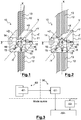
- the figure 4 schematically represents an example of implementation of the method 50 of attitude control of the satellite of the figure 1 in survival mode.
- said satellite 10 is in polar orbit and the ascending point of the orbit is at midday or midnight (in other words, the Sun S is in the plane of the orbit of the satellite 10).
- the satellite 10 moves on its orbit with an orbital pulse ⁇ 0 .
- the local terrestrial magnetic field at the satellite 10 in an inertial frame, turns on itself at twice the orbital pulse ⁇ 0 , as the satellite 10 moves on its orbit.
- the magneto-couplers 15 By controlling the magneto-couplers 15 so as to form the magnetic moment of survival, which is non-zero and constant over time, the satellite 10 follows the lines of force of the Earth's magnetic field, which causes the rotation of said satellite 10 on itself at twice the orbital pulse ⁇ 0 .
- the satellite 10 it is therefore possible to force the satellite 10 to be placed in one or other of the configurations of parts a) and b) of the figure 4 , by choosing a suitable direction of the magnetic survival moment Ms along the X axis and a suitable direction of the kinetic moment of survival Hs along the Y axis. It is further noted that, for a given kinetic moment of survival Hs, the configuration of part b) can be obtained, from the configuration of part a), by a simple inversion of the polarity of the magnetic moment of survival Ms to module
- the magnetic survival moment Ms and the kinetic moment of survival Hs are predetermined so as to place the satellite 10 in the configuration of part b).
- the photosensitive surfaces 13 of the solar generators 12 are then sunny twice in orbit of the satellite 10, and the electrical power generated is 1.5 to 2 times greater than that generated in the configuration of part a).
- the areas of the photosensitive surfaces 13 are dimensioned to ensure that the electrical power thus generated is sufficient to guarantee the electrical autonomy of a platform of the satellite 10 during the survival mode.
- the magnetic moment of survival Ms and the kinetic moment of survival Hs used in the example illustrated by the figure 4 can be used for the satellite 10 of the figure 2 in polar orbit with an ascending node at noon or midnight.
- the kinetic moment of survival Hs forms, with the plane of each solar generator 12, an angle equal to 45 ° modulo 90 °.
- the figure 5 schematically represents an example of implementation of the method 50 of attitude control of the satellite of the figure 1 in survival mode.
- said satellite 10 is in polar orbit and the ascending point of the orbit is at six o'clock or eighteen o'clock.
- the magnetic moment of survival Ms is parallel to the X axis of the satellite reference, and the kinetic moment of survival Hs is parallel to the axis Z.
- the sense of the kinetic moment of survival Ms and the direction of the kinetic moment of survival can be chosen so as to ensure that the photosensitive surfaces 13 of the solar generators 12 will be sunny throughout the duration of the orbit.
- the polarity of the magnetic survival moment Ms (that is, the direction of the magnetic survival moment Ms along the X axis) and / or the kinetics of the kinetic moment of survival Hs (that is, the say the direction of kinetic moment of survival Hs along the Y axis) can be modified, to modules
- of the order of 150 A ⁇ m 2 will provide a sufficient return torque to compensate for most disturbing couples (essentially the effect of the gravity gradient).
- of the order of 15 N ⁇ m ⁇ s will generally be sufficient to block the angular position of the satellite 10 around the local terrestrial magnetic field.
- the invention also relates to a method 60 for remote control of the satellite 10 by a ground station (not shown in the figures), represented on the figure 3 .
- the remote control method 60 comprises, when the satellite 10 is not in survival mode, a recurrent updating step 61 during which the station sends commands to the satellite 10. These commands are intended to update the instructions of magnetic survival moment Ms and survival kinetic moment Hs stored in the memory of the control module.
- the control module stores, during the step 51 of memorization, the instructions updated according to the commands received from the ground station.
- the update step 61 is executed with each six-hour variation of the solar time of the ascending node of the satellite orbit 10. None, however, precludes performing step 61 of updating for different variations of the solar time of the ascending node of the satellite orbit 10, less than or greater than six hours.
- the updates of the instructions for magnetic moment of survival Ms and kinetic moment of survival Hs aim to make them better adapted to the future orbits of satellite 10, in the event that said satellite 10 would go into survival mode.
- are preferably kept constant, but nothing excludes updating them as well.
- each update is particularly simple and can consist of a polarity inversion of the magnetic survival moment Ms and / or a reversal of the kinetics of the kinetic moment of survival Hs, while ensuring that the photosensitive surfaces 13 of the solar generators 12 are sunny at least once regardless of the orbit of the satellite 10.
- satellite 10 of the figure 1 by considering a kinetic moment of survival Hs forming, with the plane of each solar generator 12, an angle of non-zero value modulo 90 °, for example between 10 ° and 80 ° modulo 90 °.
- the invention has been described by considering a satellite 10 having several magnetocouplers 15 and several flywheels 16.
- the magneto-coupler 15 and the flywheel 16 must be arranged in the satellite 10 in the expected directions of the magnetic moment of survival and the kinetic moment of survival.
- several magneto-couplers will be necessary if these must be implemented to form a damping magnetic moment, and several flywheels will be necessary if they must be implemented to stabilize the attitude of the satellite 10 along three axes outside the survival mode.
- the invention has been described mainly considering a satellite 10 in polar orbit.
- the invention is however applicable to any type of inclined low orbit.
- the invention finds a particularly advantageous application in the case of circular orbits, but is also applicable to non-circular orbits (for example in the case of deorbitation).
- the invention has been described considering a satellite 10 having two solar generators 12. However, it is understood that the invention is generalizable to any number of solar generators 12, equal to or greater than one.
Landscapes
- Engineering & Computer Science (AREA)
- Remote Sensing (AREA)
- Aviation & Aerospace Engineering (AREA)
- Chemical & Material Sciences (AREA)
- Life Sciences & Earth Sciences (AREA)
- Combustion & Propulsion (AREA)
- Radar, Positioning & Navigation (AREA)
- Sustainable Development (AREA)
- Environmental & Geological Engineering (AREA)
- General Life Sciences & Earth Sciences (AREA)
- Geochemistry & Mineralogy (AREA)
- Geology (AREA)
- Control Of Position, Course, Altitude, Or Attitude Of Moving Bodies (AREA)
Claims (15)
- Verfahren (50) zur Lageüberwachung eines Satelliten (10) in Überlebensmodus in niedriger geneigter Umlaufbahn, wobei der Satellit (10) einen Solargenerator (12), einen Magnetkoppler (15) und ein Schwungrad (16) umfasst, dadurch gekennzeichnet, dass das Verfahren (50) umfasst:- einen dem Überlebensmodus vorausgehenden Schritt (51) des Speicherns eines als "Überlebens-Magnetmoment" bezeichneten konstanten inneren Magnetmoment-Sollwerts von ungleich Null in einer mit dem Satelliten (10) verknüpften Satellitenmarke, und eines als "Überlebens-Bewegungsmoment" bezeichneten konstanten inneren Bewegungsmoment-Sollwerts von ungleich Null in der Satellitenmarke, wobei das Überlebens-Magnetmoment und das Überlebens-Bewegungsmoment so vordefiniert sind, dass sichergestellt wird, dass eine lichtempfindliche Fläche (13) des Solargenerators (12) mindestens ein Mal im Laufe einer Umlaufbahn des Satelliten (10) von der Sonne beschienen wird,- einen Schritt (52) des Steuerns des Magnetkopplers (15) und des Schwungrads (16) so, dass während mindestens eines Teils des Überlebensmodus gleichzeitig das Überlebens-Magnetmoment und das Überlebens-Bewegungsmoment gebildet werden.
- Verfahren (50) nach Anspruch 1, dadurch gekennzeichnet, dass wenn der Satellit (10) mehrere Magnetkoppler (15) und eine Vorrichtung zum Messen des lokalen Erdmagnetfelds umfasst, das Verfahren Schritte umfasst des:- (53) Bestimmens, in Abhängigkeit von Messungen des lokalen Erdmagnetfelds, eines als "Dämpfungs-Magnetmoment" bezeichneten inneren Magnetmoments, das zu bilden ist, um ein magnetisches Drehmoment an den Satelliten (10) anzulegen, das sich den Abweichungen des lokalen Erdmagnetfelds in der Satellitenmarke entgegensetzt,- (52) Steuerns der Magnetkoppler (15) so, dass das Dämpfungs-Magnetmoment dem Überlebens-Magnetmoment überlagert wird.
- Verfahren (50) nach einem der vorstehenden Ansprüche, dadurch gekennzeichnet, dass wenn der Solargenerator (12) entlang einer X-Achse der Satellitenmarke angeordnet ist, das Überlebens-Magnetmoment zur X-Achse parallel ist und Überlebens-Bewegungsmoment zur X-Achse orthogonal ist.
- Verfahren (50) nach Anspruch 3, dadurch gekennzeichnet, dass wenn der Solargenerator (12) im Wesentlichen eben ist, das Überlebens-Bewegungsmoment zur Ebene des Solargenerators einen Winkel mit einem Wert von ungleich Null Modulo 90° bildet.
- Verfahren (50) nach einem der Ansprüche 1 bis 2, dadurch gekennzeichnet, dass wenn der ansteigende Knoten der Umlaufbahn nahe Mittag oder Mitternacht ist und der Solargenerator (12) entlang einer X-Achse der Satellitenmarke angeordnet ist, das Überlebens-Magnetmoment zur X-Achse orthogonal ist und das Überlebens-Bewegungsmoment zur X-Achse parallel ist.
- Verfahren (50) nach einem der vorstehenden Ansprüche, dadurch gekennzeichnet, dass wenn der ansteigende Knoten der Umlaufbahn nahe Mittag oder Mitternacht ist, das Überlebens-Magnetmoment und das Überlebens-Bewegungsmoment so vorbestimmt sind, dass sichergestellt wird, dass die lichtempfindliche Fläche (13) des Solargenerators (12) mindestens zwei Mal im Laufe einer Umlaufbahn des Satelliten (10) von der Sonne beschienen wird.
- Verfahren (50) nach einem der vorstehenden Ansprüche, dadurch gekennzeichnet, dass die Umlaufbahn des Satelliten (10) im Wesentlichen polar ist.
- Computerprogrammprodukt, dadurch gekennzeichnet, dass es einen Satz Programmcodeanweisungen umfasst, die, wenn sie von einem Prozessor ausgeführt werden, ein Verfahren (50) zur Lageüberwachung nach einem der vorstehenden Ansprüche umsetzen.
- Satellit (10) in niedriger geneigter Umlaufbahn, der einen Solargenerator (12), einen Magnetkoppler (15), ein Schwungrad (16) und ein Modul zum Steuern des Magnetkopplers (15) und des Schwungrads (16) umfasst, dadurch gekennzeichnet, dass das Steuermodul einen Speicher umfasst, in dem ein als "Überlebens-Magnetmoment" bezeichneter konstanter innerer Magnetmoment-Sollwert von ungleich Null in einer mit dem Satelliten (10) verknüpften Satellitenmarke, und ein als "Überlebens-Bewegungsmoment" bezeichneter konstanter innerer Bewegungsmoment-Sollwert von ungleich Null in der Satellitenmarke gespeichert werden, und dadurch, dass das Steuermodul dafür konfiguriert ist, wenn sich der Satellit (10) in Überlebensmodus befindet, den Magnetkoppler (15) und das Schwungrad (16) so zu steuern, dass während mindestens eines Teils des Überlebensmodus gleichzeitig das Überlebens-Magnetmoment und das Überlebens-Bewegungsmoment gebildet werden.
- Satellit (10) nach Anspruch 9, dadurch gekennzeichnet, dass er mehrere Magnetkoppler (15) und eine Vorrichtung zum Messen des lokalen Erdmagnetfelds umfasst, und dadurch, dass das Steuermodul dafür konfiguriert ist, wenn sich der Satellit (10) in Überlebensmodus befindet:- in Abhängigkeit von Messungen des lokalen Erdmagnetfelds ein als "Dämpfungs-Magnetmoment" bezeichnetes inneres Magnetmoment zu bestimmen, das zu bilden ist, um ein magnetisches Drehmoment an den Satelliten (10) anzulegen, das dazu geeignet ist, sich den Abweichungen des lokalen Erdmagnetfelds in der Satellitenmarke entgegenzusetzen,- die Magnetkoppler (15) so zu steuern, dass das Dämpfungs-Magnetmoment dem Überlebens-Magnetmoment überlagert wird.
- Satellit (10) nach einem der Ansprüche 9 bis 10, dadurch gekennzeichnet, dass wenn der Solargenerator (12) entlang einer X-Achse der Satellitenmarke angeordnet ist, das Überlebens-Magnetmoment zur X-Achse parallel ist und Überlebens-Bewegungsmoment zur X-Achse orthogonal ist.
- Satellit (10) nach Anspruch 11, dadurch gekennzeichnet, dass wenn der Solargenerator (12) im Wesentlichen eben ist, das Überlebens-Bewegungsmoment zur Ebene des Solargenerators einen Winkel mit einem Wert von ungleich Null Modulo 90° bildet.
- Verfahren (60) zum Fernsteuern eines Satelliten (10) nach einem der Ansprüche 9 bis 12, dadurch gekennzeichnet, dass wenn die Umlaufbahn des Satelliten driftet, das Verfahren, wenn sich der Satellit (10) nicht in Überlebensmodus befindet, einen wiederkehrenden Schritt (61) des Aktualisierens der Überlebens-Magnetmoment- und Überlebens-Bewegungsmoment-Sollwerte umfasst, die im Speicher des Steuermoduls gespeichert sind.
- Verfahren (60) nach Anspruch 13, dadurch gekennzeichnet, dass der Schritt (61) des Aktualisierens bei jeder Abweichung von sechs Stunden der Sonnenzeit des ansteigenden Knotens von der Umlaufbahn des Satelliten (10) ausgeführt wird.
- Verfahren (60) nach einem der Ansprüche 13 bis 14, dadurch gekennzeichnet, dass wenn der Solargenerator (12) im Wesentlichen eben ist und das Überlebens-Bewegungsmoment zur Ebene des Solargenerators einen Winkel mit einem Wert von ungleich Null Modulo 90° bildet, jede Aktualisierung in einer Umpolung des Überlebens-Magnetmoments und/oder einer Umpolung des Überlebens-Bewegungsmoments besteht.
Applications Claiming Priority (2)
| Application Number | Priority Date | Filing Date | Title |
|---|---|---|---|
| FR1459420A FR3026858B1 (fr) | 2014-10-02 | 2014-10-02 | Procede de controle d'attitude d'un satellite en mode survie, satellite adapte et procede de commande a distance d'un tel satellite |
| PCT/FR2015/052654 WO2016051113A1 (fr) | 2014-10-02 | 2015-10-02 | Procédé de contrôle d'attitude d'un satellite en mode survie, satellite adapté et procédé de commande à distance d'un tel satellite |
Publications (2)
| Publication Number | Publication Date |
|---|---|
| EP3201091A1 EP3201091A1 (de) | 2017-08-09 |
| EP3201091B1 true EP3201091B1 (de) | 2019-06-12 |
Family
ID=52684311
Family Applications (1)
| Application Number | Title | Priority Date | Filing Date |
|---|---|---|---|
| EP15787001.5A Active EP3201091B1 (de) | 2014-10-02 | 2015-10-02 | Verfahren zur überwachung der lage eines satelliten in überlebensmodus, angepasste satellit und verfahren zur fernsteuerung solch eines satelliten |
Country Status (3)
| Country | Link |
|---|---|
| EP (1) | EP3201091B1 (de) |
| FR (1) | FR3026858B1 (de) |
| WO (1) | WO2016051113A1 (de) |
Families Citing this family (7)
| Publication number | Priority date | Publication date | Assignee | Title |
|---|---|---|---|---|
| CN106828981B (zh) * | 2017-03-13 | 2020-01-03 | 上海航天控制技术研究所 | 斜飞大惯量耦合卫星的常值干扰力矩补偿方法和系统 |
| CN108045600A (zh) * | 2017-10-23 | 2018-05-18 | 上海卫星工程研究所 | 双超卫星平台载荷舱复合控制方法 |
| CN109649691B (zh) * | 2018-12-27 | 2021-07-13 | 上海航天控制技术研究所 | 一种偏置动量卫星单飞轮与磁联合控制方法和系统 |
| CN109649693B (zh) * | 2019-01-21 | 2021-12-14 | 上海微小卫星工程中心 | 一种纯磁控自旋对日定向方法 |
| FR3093326A1 (fr) * | 2019-03-01 | 2020-09-04 | Centre National d'Études Spatiales | Procédé de contrôle de l’attitude d’un satellite en orbite basse |
| FR3093998B1 (fr) * | 2019-03-20 | 2021-09-10 | Airbus Defence & Space Sas | Procédé de contrôle d’attitude d’un satellite en mode survie sans connaissance a priori de l’heure locale de l’orbite du satellite |
| CN110389592B (zh) * | 2019-07-18 | 2020-12-01 | 南京航空航天大学 | 一种基于分布式智能飞轮的航天器姿态控制方法 |
Family Cites Families (7)
| Publication number | Priority date | Publication date | Assignee | Title |
|---|---|---|---|---|
| US5123617A (en) * | 1990-03-05 | 1992-06-23 | General Electric Company | Spacecraft momentum unloading using controlled magnetic torques |
| FR2670745B1 (fr) * | 1990-12-21 | 1993-04-16 | Aerospatiale | Systeme de controle d'attitude pour satellite stabilise 3-axes sur orbite a faible inclinaison. |
| FR2742243B1 (fr) * | 1995-12-06 | 1998-02-13 | Matra Marconi Space France | Procede de commande d'attitude d'un satellite en orbite basse, a acquisition solaire |
| FR2809502B1 (fr) * | 2000-05-29 | 2002-08-16 | Matra Marconi Space France | Procede de commande d'attitude d'un satellite en orbite terrestre basse |
| FR2937954B1 (fr) * | 2008-10-31 | 2011-07-29 | Thales Sa | Procede et systeme de desaturation des roues d'inertie d'un engin spatial |
| FR2980176A1 (fr) * | 2011-09-19 | 2013-03-22 | Astrium Sas | Procede de controle d'attitude d'un satellite et satellite commande en attitude |
| FR2994287B1 (fr) * | 2012-08-03 | 2016-11-04 | Thales Sa | Dispositif et procede pour desorbitation de satellite |
-
2014
- 2014-10-02 FR FR1459420A patent/FR3026858B1/fr not_active Expired - Fee Related
-
2015
- 2015-10-02 EP EP15787001.5A patent/EP3201091B1/de active Active
- 2015-10-02 WO PCT/FR2015/052654 patent/WO2016051113A1/fr active Application Filing
Also Published As
| Publication number | Publication date |
|---|---|
| FR3026858A1 (fr) | 2016-04-08 |
| WO2016051113A1 (fr) | 2016-04-07 |
| EP3201091A1 (de) | 2017-08-09 |
| FR3026858B1 (fr) | 2016-12-09 |
Similar Documents
| Publication | Publication Date | Title |
|---|---|---|
| EP3201091B1 (de) | Verfahren zur überwachung der lage eines satelliten in überlebensmodus, angepasste satellit und verfahren zur fernsteuerung solch eines satelliten | |
| EP3381813B1 (de) | Satellit, der elektrische antriebsmittel umfasst, die von bewegungsmitteln und zusätzlichen elektrischen antriebsmitteln mit fester ausrichtung getragen werden | |
| EP0435708B1 (de) | Verfahren zur Steuerung der Neigung eines Satelliten bezüglich der Roll- und der Gierachse | |
| EP3074309B1 (de) | Verfahren und vorrichtung zur steuerung einer sonnenlichtaufnahmephase eines raumfahrzeuges | |
| EP3248079B1 (de) | Verfahren und vorrichtung zur steuerung der stellung eines raumfahrzeugs | |
| EP2690020B1 (de) | Verfahren zur Reduzierung des Drehimpulses und zur Fluglageregelung eines Raumfahrzeugs | |
| CA2192050C (fr) | Procede de commande d'attitude d'un satellite en orbite basse, a acquisition solaire | |
| EP0493228B1 (de) | Verfahren zur Wiederlangung der Lage eines dreiachs-stabilisierten Satelliten mittels Sternidentifizierung | |
| EP2181923A1 (de) | Entsättigungsverfahren und -system der Trägheitsräder eines Raumschiffs | |
| EP2878539B1 (de) | Düsensystem und verfahren zur kontrolle der umlaufbahn und des verhaltens für geostationären satelliten | |
| EP3921235B1 (de) | Verfahren zur lageregelung eines satelliten im überlebensmodus ohne a-priori-kenntnis der lokalen umlaufzeit des satelliten | |
| EP2914497B1 (de) | Verfahren zum steuern von magnetischen drehmomenterzeugern eines lageregelungssystems eines raumfahrzeuges | |
| CA1267949A (fr) | Procedure de repointage rapide des satellites a pointage terrestre, et notamment des satellites geostationnaires de telecommunication a stabilisation par volant d'inertie | |
| EP3959142B1 (de) | Verfahren zur umlaufbahnsteuerung und -desaturation eines satelliten mittels gelenkarmen, die eine antriebseinheit tragen | |
| EP3956230B1 (de) | Verfahren zur umlaufbahnsteuerung und -desaturation eines satelliten mittels einzelgelenkarm, der eine antriebseinheit trägt | |
| EP1312997B1 (de) | Steuerungsverfahren zur Lageregelung und Stabilisierung eines Satelliten in niedriger Umlaufbahn, durch Kopplung mit dem Erdmagnetfeld | |
| EP1308813A1 (de) | Verfahren zur Lagesteuerung eines Satelliten auf einer niedrigen Umlaufbahn |
Legal Events
| Date | Code | Title | Description |
|---|---|---|---|
| STAA | Information on the status of an ep patent application or granted ep patent |
Free format text: STATUS: THE INTERNATIONAL PUBLICATION HAS BEEN MADE |
|
| PUAI | Public reference made under article 153(3) epc to a published international application that has entered the european phase |
Free format text: ORIGINAL CODE: 0009012 |
|
| STAA | Information on the status of an ep patent application or granted ep patent |
Free format text: STATUS: REQUEST FOR EXAMINATION WAS MADE |
|
| 17P | Request for examination filed |
Effective date: 20170320 |
|
| AK | Designated contracting states |
Kind code of ref document: A1 Designated state(s): AL AT BE BG CH CY CZ DE DK EE ES FI FR GB GR HR HU IE IS IT LI LT LU LV MC MK MT NL NO PL PT RO RS SE SI SK SM TR |
|
| AX | Request for extension of the european patent |
Extension state: BA ME |
|
| DAV | Request for validation of the european patent (deleted) | ||
| DAX | Request for extension of the european patent (deleted) | ||
| REG | Reference to a national code |
Ref country code: DE Ref legal event code: R079 Ref document number: 602015031918 Country of ref document: DE Free format text: PREVIOUS MAIN CLASS: B64G0001240000 Ipc: B64G0001280000 |
|
| RIC1 | Information provided on ipc code assigned before grant |
Ipc: B64G 1/32 20060101ALI20181112BHEP Ipc: B64G 1/28 20060101AFI20181112BHEP Ipc: B64G 1/44 20060101ALI20181112BHEP |
|
| GRAP | Despatch of communication of intention to grant a patent |
Free format text: ORIGINAL CODE: EPIDOSNIGR1 |
|
| STAA | Information on the status of an ep patent application or granted ep patent |
Free format text: STATUS: GRANT OF PATENT IS INTENDED |
|
| INTG | Intention to grant announced |
Effective date: 20190103 |
|
| GRAS | Grant fee paid |
Free format text: ORIGINAL CODE: EPIDOSNIGR3 |
|
| GRAA | (expected) grant |
Free format text: ORIGINAL CODE: 0009210 |
|
| STAA | Information on the status of an ep patent application or granted ep patent |
Free format text: STATUS: THE PATENT HAS BEEN GRANTED |
|
| RAP1 | Party data changed (applicant data changed or rights of an application transferred) |
Owner name: AIRBUS DEFENCE AND SPACE SAS Owner name: CENTRE NATIONAL D'ETUDES SPATIALES (CNES) |
|
| AK | Designated contracting states |
Kind code of ref document: B1 Designated state(s): AL AT BE BG CH CY CZ DE DK EE ES FI FR GB GR HR HU IE IS IT LI LT LU LV MC MK MT NL NO PL PT RO RS SE SI SK SM TR |
|
| REG | Reference to a national code |
Ref country code: GB Ref legal event code: FG4D Free format text: NOT ENGLISH |
|
| REG | Reference to a national code |
Ref country code: CH Ref legal event code: EP |
|
| REG | Reference to a national code |
Ref country code: AT Ref legal event code: REF Ref document number: 1142249 Country of ref document: AT Kind code of ref document: T Effective date: 20190615 |
|
| REG | Reference to a national code |
Ref country code: DE Ref legal event code: R096 Ref document number: 602015031918 Country of ref document: DE |
|
| REG | Reference to a national code |
Ref country code: IE Ref legal event code: FG4D Free format text: LANGUAGE OF EP DOCUMENT: FRENCH |
|
| REG | Reference to a national code |
Ref country code: NL Ref legal event code: MP Effective date: 20190612 |
|
| REG | Reference to a national code |
Ref country code: LT Ref legal event code: MG4D |
|
| PG25 | Lapsed in a contracting state [announced via postgrant information from national office to epo] |
Ref country code: NO Free format text: LAPSE BECAUSE OF FAILURE TO SUBMIT A TRANSLATION OF THE DESCRIPTION OR TO PAY THE FEE WITHIN THE PRESCRIBED TIME-LIMIT Effective date: 20190912 Ref country code: HR Free format text: LAPSE BECAUSE OF FAILURE TO SUBMIT A TRANSLATION OF THE DESCRIPTION OR TO PAY THE FEE WITHIN THE PRESCRIBED TIME-LIMIT Effective date: 20190612 Ref country code: LT Free format text: LAPSE BECAUSE OF FAILURE TO SUBMIT A TRANSLATION OF THE DESCRIPTION OR TO PAY THE FEE WITHIN THE PRESCRIBED TIME-LIMIT Effective date: 20190612 Ref country code: AL Free format text: LAPSE BECAUSE OF FAILURE TO SUBMIT A TRANSLATION OF THE DESCRIPTION OR TO PAY THE FEE WITHIN THE PRESCRIBED TIME-LIMIT Effective date: 20190612 Ref country code: SE Free format text: LAPSE BECAUSE OF FAILURE TO SUBMIT A TRANSLATION OF THE DESCRIPTION OR TO PAY THE FEE WITHIN THE PRESCRIBED TIME-LIMIT Effective date: 20190612 Ref country code: FI Free format text: LAPSE BECAUSE OF FAILURE TO SUBMIT A TRANSLATION OF THE DESCRIPTION OR TO PAY THE FEE WITHIN THE PRESCRIBED TIME-LIMIT Effective date: 20190612 |
|
| PG25 | Lapsed in a contracting state [announced via postgrant information from national office to epo] |
Ref country code: BG Free format text: LAPSE BECAUSE OF FAILURE TO SUBMIT A TRANSLATION OF THE DESCRIPTION OR TO PAY THE FEE WITHIN THE PRESCRIBED TIME-LIMIT Effective date: 20190912 Ref country code: GR Free format text: LAPSE BECAUSE OF FAILURE TO SUBMIT A TRANSLATION OF THE DESCRIPTION OR TO PAY THE FEE WITHIN THE PRESCRIBED TIME-LIMIT Effective date: 20190913 Ref country code: LV Free format text: LAPSE BECAUSE OF FAILURE TO SUBMIT A TRANSLATION OF THE DESCRIPTION OR TO PAY THE FEE WITHIN THE PRESCRIBED TIME-LIMIT Effective date: 20190612 Ref country code: RS Free format text: LAPSE BECAUSE OF FAILURE TO SUBMIT A TRANSLATION OF THE DESCRIPTION OR TO PAY THE FEE WITHIN THE PRESCRIBED TIME-LIMIT Effective date: 20190612 |
|
| REG | Reference to a national code |
Ref country code: AT Ref legal event code: MK05 Ref document number: 1142249 Country of ref document: AT Kind code of ref document: T Effective date: 20190612 |
|
| PG25 | Lapsed in a contracting state [announced via postgrant information from national office to epo] |
Ref country code: SK Free format text: LAPSE BECAUSE OF FAILURE TO SUBMIT A TRANSLATION OF THE DESCRIPTION OR TO PAY THE FEE WITHIN THE PRESCRIBED TIME-LIMIT Effective date: 20190612 Ref country code: RO Free format text: LAPSE BECAUSE OF FAILURE TO SUBMIT A TRANSLATION OF THE DESCRIPTION OR TO PAY THE FEE WITHIN THE PRESCRIBED TIME-LIMIT Effective date: 20190612 Ref country code: PT Free format text: LAPSE BECAUSE OF FAILURE TO SUBMIT A TRANSLATION OF THE DESCRIPTION OR TO PAY THE FEE WITHIN THE PRESCRIBED TIME-LIMIT Effective date: 20191014 Ref country code: NL Free format text: LAPSE BECAUSE OF FAILURE TO SUBMIT A TRANSLATION OF THE DESCRIPTION OR TO PAY THE FEE WITHIN THE PRESCRIBED TIME-LIMIT Effective date: 20190612 Ref country code: CZ Free format text: LAPSE BECAUSE OF FAILURE TO SUBMIT A TRANSLATION OF THE DESCRIPTION OR TO PAY THE FEE WITHIN THE PRESCRIBED TIME-LIMIT Effective date: 20190612 Ref country code: EE Free format text: LAPSE BECAUSE OF FAILURE TO SUBMIT A TRANSLATION OF THE DESCRIPTION OR TO PAY THE FEE WITHIN THE PRESCRIBED TIME-LIMIT Effective date: 20190612 Ref country code: AT Free format text: LAPSE BECAUSE OF FAILURE TO SUBMIT A TRANSLATION OF THE DESCRIPTION OR TO PAY THE FEE WITHIN THE PRESCRIBED TIME-LIMIT Effective date: 20190612 |
|
| PG25 | Lapsed in a contracting state [announced via postgrant information from national office to epo] |
Ref country code: SM Free format text: LAPSE BECAUSE OF FAILURE TO SUBMIT A TRANSLATION OF THE DESCRIPTION OR TO PAY THE FEE WITHIN THE PRESCRIBED TIME-LIMIT Effective date: 20190612 Ref country code: ES Free format text: LAPSE BECAUSE OF FAILURE TO SUBMIT A TRANSLATION OF THE DESCRIPTION OR TO PAY THE FEE WITHIN THE PRESCRIBED TIME-LIMIT Effective date: 20190612 Ref country code: IS Free format text: LAPSE BECAUSE OF FAILURE TO SUBMIT A TRANSLATION OF THE DESCRIPTION OR TO PAY THE FEE WITHIN THE PRESCRIBED TIME-LIMIT Effective date: 20191012 Ref country code: IT Free format text: LAPSE BECAUSE OF FAILURE TO SUBMIT A TRANSLATION OF THE DESCRIPTION OR TO PAY THE FEE WITHIN THE PRESCRIBED TIME-LIMIT Effective date: 20190612 |
|
| REG | Reference to a national code |
Ref country code: DE Ref legal event code: R097 Ref document number: 602015031918 Country of ref document: DE |
|
| PG25 | Lapsed in a contracting state [announced via postgrant information from national office to epo] |
Ref country code: TR Free format text: LAPSE BECAUSE OF FAILURE TO SUBMIT A TRANSLATION OF THE DESCRIPTION OR TO PAY THE FEE WITHIN THE PRESCRIBED TIME-LIMIT Effective date: 20190612 |
|
| PLBE | No opposition filed within time limit |
Free format text: ORIGINAL CODE: 0009261 |
|
| STAA | Information on the status of an ep patent application or granted ep patent |
Free format text: STATUS: NO OPPOSITION FILED WITHIN TIME LIMIT |
|
| PG25 | Lapsed in a contracting state [announced via postgrant information from national office to epo] |
Ref country code: PL Free format text: LAPSE BECAUSE OF FAILURE TO SUBMIT A TRANSLATION OF THE DESCRIPTION OR TO PAY THE FEE WITHIN THE PRESCRIBED TIME-LIMIT Effective date: 20190612 Ref country code: DK Free format text: LAPSE BECAUSE OF FAILURE TO SUBMIT A TRANSLATION OF THE DESCRIPTION OR TO PAY THE FEE WITHIN THE PRESCRIBED TIME-LIMIT Effective date: 20190612 |
|
| 26N | No opposition filed |
Effective date: 20200313 |
|
| PG25 | Lapsed in a contracting state [announced via postgrant information from national office to epo] |
Ref country code: MC Free format text: LAPSE BECAUSE OF FAILURE TO SUBMIT A TRANSLATION OF THE DESCRIPTION OR TO PAY THE FEE WITHIN THE PRESCRIBED TIME-LIMIT Effective date: 20190612 Ref country code: IS Free format text: LAPSE BECAUSE OF FAILURE TO SUBMIT A TRANSLATION OF THE DESCRIPTION OR TO PAY THE FEE WITHIN THE PRESCRIBED TIME-LIMIT Effective date: 20200224 Ref country code: SI Free format text: LAPSE BECAUSE OF FAILURE TO SUBMIT A TRANSLATION OF THE DESCRIPTION OR TO PAY THE FEE WITHIN THE PRESCRIBED TIME-LIMIT Effective date: 20190612 |
|
| REG | Reference to a national code |
Ref country code: CH Ref legal event code: PL |
|
| PG2D | Information on lapse in contracting state deleted |
Ref country code: IS |
|
| PG25 | Lapsed in a contracting state [announced via postgrant information from national office to epo] |
Ref country code: LI Free format text: LAPSE BECAUSE OF NON-PAYMENT OF DUE FEES Effective date: 20191031 Ref country code: CH Free format text: LAPSE BECAUSE OF NON-PAYMENT OF DUE FEES Effective date: 20191031 Ref country code: LU Free format text: LAPSE BECAUSE OF NON-PAYMENT OF DUE FEES Effective date: 20191002 |
|
| REG | Reference to a national code |
Ref country code: BE Ref legal event code: MM Effective date: 20191031 |
|
| PG25 | Lapsed in a contracting state [announced via postgrant information from national office to epo] |
Ref country code: BE Free format text: LAPSE BECAUSE OF NON-PAYMENT OF DUE FEES Effective date: 20191031 |
|
| PG25 | Lapsed in a contracting state [announced via postgrant information from national office to epo] |
Ref country code: IE Free format text: LAPSE BECAUSE OF NON-PAYMENT OF DUE FEES Effective date: 20191002 |
|
| PG25 | Lapsed in a contracting state [announced via postgrant information from national office to epo] |
Ref country code: CY Free format text: LAPSE BECAUSE OF FAILURE TO SUBMIT A TRANSLATION OF THE DESCRIPTION OR TO PAY THE FEE WITHIN THE PRESCRIBED TIME-LIMIT Effective date: 20190612 |
|
| PG25 | Lapsed in a contracting state [announced via postgrant information from national office to epo] |
Ref country code: MT Free format text: LAPSE BECAUSE OF FAILURE TO SUBMIT A TRANSLATION OF THE DESCRIPTION OR TO PAY THE FEE WITHIN THE PRESCRIBED TIME-LIMIT Effective date: 20190612 Ref country code: HU Free format text: LAPSE BECAUSE OF FAILURE TO SUBMIT A TRANSLATION OF THE DESCRIPTION OR TO PAY THE FEE WITHIN THE PRESCRIBED TIME-LIMIT; INVALID AB INITIO Effective date: 20151002 |
|
| PG25 | Lapsed in a contracting state [announced via postgrant information from national office to epo] |
Ref country code: MK Free format text: LAPSE BECAUSE OF FAILURE TO SUBMIT A TRANSLATION OF THE DESCRIPTION OR TO PAY THE FEE WITHIN THE PRESCRIBED TIME-LIMIT Effective date: 20190612 |
|
| PGFP | Annual fee paid to national office [announced via postgrant information from national office to epo] |
Ref country code: GB Payment date: 20231030 Year of fee payment: 9 |
|
| PGFP | Annual fee paid to national office [announced via postgrant information from national office to epo] |
Ref country code: FR Payment date: 20231027 Year of fee payment: 9 Ref country code: DE Payment date: 20231025 Year of fee payment: 9 |