EP1002685B1 - Control of pump for hydraulic front wheel drive - Google Patents
Control of pump for hydraulic front wheel drive Download PDFInfo
- Publication number
- EP1002685B1 EP1002685B1 EP99122704A EP99122704A EP1002685B1 EP 1002685 B1 EP1002685 B1 EP 1002685B1 EP 99122704 A EP99122704 A EP 99122704A EP 99122704 A EP99122704 A EP 99122704A EP 1002685 B1 EP1002685 B1 EP 1002685B1
- Authority
- EP
- European Patent Office
- Prior art keywords
- pump
- flow
- signal
- motor
- displacement
- Prior art date
- Legal status (The legal status is an assumption and is not a legal conclusion. Google has not performed a legal analysis and makes no representation as to the accuracy of the status listed.)
- Expired - Lifetime
Links
Images


Classifications
-
- F—MECHANICAL ENGINEERING; LIGHTING; HEATING; WEAPONS; BLASTING
- F16—ENGINEERING ELEMENTS AND UNITS; GENERAL MEASURES FOR PRODUCING AND MAINTAINING EFFECTIVE FUNCTIONING OF MACHINES OR INSTALLATIONS; THERMAL INSULATION IN GENERAL
- F16H—GEARING
- F16H61/00—Control functions within control units of change-speed- or reversing-gearings for conveying rotary motion ; Control of exclusively fluid gearing, friction gearing, gearings with endless flexible members or other particular types of gearing
- F16H61/38—Control of exclusively fluid gearing
- F16H61/40—Control of exclusively fluid gearing hydrostatic
- F16H61/4192—Detecting malfunction or potential malfunction, e.g. fail safe
-
- B—PERFORMING OPERATIONS; TRANSPORTING
- B60—VEHICLES IN GENERAL
- B60K—ARRANGEMENT OR MOUNTING OF PROPULSION UNITS OR OF TRANSMISSIONS IN VEHICLES; ARRANGEMENT OR MOUNTING OF PLURAL DIVERSE PRIME-MOVERS IN VEHICLES; AUXILIARY DRIVES FOR VEHICLES; INSTRUMENTATION OR DASHBOARDS FOR VEHICLES; ARRANGEMENTS IN CONNECTION WITH COOLING, AIR INTAKE, GAS EXHAUST OR FUEL SUPPLY OF PROPULSION UNITS IN VEHICLES
- B60K17/00—Arrangement or mounting of transmissions in vehicles
- B60K17/04—Arrangement or mounting of transmissions in vehicles characterised by arrangement, location, or kind of gearing
- B60K17/10—Arrangement or mounting of transmissions in vehicles characterised by arrangement, location, or kind of gearing of fluid gearing
-
- E—FIXED CONSTRUCTIONS
- E02—HYDRAULIC ENGINEERING; FOUNDATIONS; SOIL SHIFTING
- E02F—DREDGING; SOIL-SHIFTING
- E02F9/00—Component parts of dredgers or soil-shifting machines, not restricted to one of the kinds covered by groups E02F3/00 - E02F7/00
- E02F9/20—Drives; Control devices
- E02F9/22—Hydraulic or pneumatic drives
- E02F9/2253—Controlling the travelling speed of vehicles, e.g. adjusting travelling speed according to implement loads, control of hydrostatic transmission
-
- E—FIXED CONSTRUCTIONS
- E02—HYDRAULIC ENGINEERING; FOUNDATIONS; SOIL SHIFTING
- E02F—DREDGING; SOIL-SHIFTING
- E02F9/00—Component parts of dredgers or soil-shifting machines, not restricted to one of the kinds covered by groups E02F3/00 - E02F7/00
- E02F9/20—Drives; Control devices
- E02F9/22—Hydraulic or pneumatic drives
- E02F9/226—Safety arrangements, e.g. hydraulic driven fans, preventing cavitation, leakage, overheating
-
- F—MECHANICAL ENGINEERING; LIGHTING; HEATING; WEAPONS; BLASTING
- F15—FLUID-PRESSURE ACTUATORS; HYDRAULICS OR PNEUMATICS IN GENERAL
- F15B—SYSTEMS ACTING BY MEANS OF FLUIDS IN GENERAL; FLUID-PRESSURE ACTUATORS, e.g. SERVOMOTORS; DETAILS OF FLUID-PRESSURE SYSTEMS, NOT OTHERWISE PROVIDED FOR
- F15B21/00—Common features of fluid actuator systems; Fluid-pressure actuator systems or details thereof, not covered by any other group of this subclass
- F15B21/08—Servomotor systems incorporating electrically operated control means
-
- F—MECHANICAL ENGINEERING; LIGHTING; HEATING; WEAPONS; BLASTING
- F16—ENGINEERING ELEMENTS AND UNITS; GENERAL MEASURES FOR PRODUCING AND MAINTAINING EFFECTIVE FUNCTIONING OF MACHINES OR INSTALLATIONS; THERMAL INSULATION IN GENERAL
- F16H—GEARING
- F16H39/00—Rotary fluid gearing using pumps and motors of the volumetric type, i.e. passing a predetermined volume of fluid per revolution
- F16H39/02—Rotary fluid gearing using pumps and motors of the volumetric type, i.e. passing a predetermined volume of fluid per revolution with liquid motors at a distance from liquid pumps
-
- F—MECHANICAL ENGINEERING; LIGHTING; HEATING; WEAPONS; BLASTING
- F16—ENGINEERING ELEMENTS AND UNITS; GENERAL MEASURES FOR PRODUCING AND MAINTAINING EFFECTIVE FUNCTIONING OF MACHINES OR INSTALLATIONS; THERMAL INSULATION IN GENERAL
- F16H—GEARING
- F16H61/00—Control functions within control units of change-speed- or reversing-gearings for conveying rotary motion ; Control of exclusively fluid gearing, friction gearing, gearings with endless flexible members or other particular types of gearing
- F16H61/38—Control of exclusively fluid gearing
- F16H61/40—Control of exclusively fluid gearing hydrostatic
- F16H61/4035—Control of circuit flow
-
- F—MECHANICAL ENGINEERING; LIGHTING; HEATING; WEAPONS; BLASTING
- F16—ENGINEERING ELEMENTS AND UNITS; GENERAL MEASURES FOR PRODUCING AND MAINTAINING EFFECTIVE FUNCTIONING OF MACHINES OR INSTALLATIONS; THERMAL INSULATION IN GENERAL
- F16H—GEARING
- F16H59/00—Control inputs to control units of change-speed-, or reversing-gearings for conveying rotary motion
- F16H59/68—Inputs being a function of gearing status
- F16H2059/6838—Sensing gearing status of hydrostatic transmissions
- F16H2059/6861—Sensing gearing status of hydrostatic transmissions the pressures, e.g. high, low or differential pressures
-
- F—MECHANICAL ENGINEERING; LIGHTING; HEATING; WEAPONS; BLASTING
- F16—ENGINEERING ELEMENTS AND UNITS; GENERAL MEASURES FOR PRODUCING AND MAINTAINING EFFECTIVE FUNCTIONING OF MACHINES OR INSTALLATIONS; THERMAL INSULATION IN GENERAL
- F16H—GEARING
- F16H61/00—Control functions within control units of change-speed- or reversing-gearings for conveying rotary motion ; Control of exclusively fluid gearing, friction gearing, gearings with endless flexible members or other particular types of gearing
- F16H2061/0075—Control functions within control units of change-speed- or reversing-gearings for conveying rotary motion ; Control of exclusively fluid gearing, friction gearing, gearings with endless flexible members or other particular types of gearing characterised by a particular control method
- F16H2061/0078—Linear control, e.g. PID, state feedback or Kalman
-
- F—MECHANICAL ENGINEERING; LIGHTING; HEATING; WEAPONS; BLASTING
- F16—ENGINEERING ELEMENTS AND UNITS; GENERAL MEASURES FOR PRODUCING AND MAINTAINING EFFECTIVE FUNCTIONING OF MACHINES OR INSTALLATIONS; THERMAL INSULATION IN GENERAL
- F16H—GEARING
- F16H61/00—Control functions within control units of change-speed- or reversing-gearings for conveying rotary motion ; Control of exclusively fluid gearing, friction gearing, gearings with endless flexible members or other particular types of gearing
- F16H61/38—Control of exclusively fluid gearing
- F16H61/40—Control of exclusively fluid gearing hydrostatic
- F16H61/42—Control of exclusively fluid gearing hydrostatic involving adjustment of a pump or motor with adjustable output or capacity
- F16H61/431—Pump capacity control by electro-hydraulic control means, e.g. using solenoid valves
Definitions
- the present invention relates generally to vehicle drive systems, and more particularly, to a control system for a variable displacement pump useable in a system for propelling a vehicle, such as an auxiliary front wheel drive system.
- the rear wheels are driven mechanically by the engine, through a mechanical transmission and differential gear set. It has become well known in the art to supplement such a main, mechanical drive system by means of a hydrostatic, auxiliary front wheel drive system, which is also sometimes referred to as a "supplemental" drive system.
- a hydrostatic, auxiliary front wheel drive system which is also sometimes referred to as a "supplemental" drive system.
- the pump of the present invention may be utilized on a vehicle having mechanically driven front wheels and hydrostatically driven rear wheels, it is especially advantageous when used on vehicles such as motor graders which typically have mechanically driven rear wheels and hydrostatically driven front wheels, and will be described in connection therewith.
- the auxiliary drive system includes a fluid pump driven by the engine for providing pressurized fluid to a pair of hydraulic motors, each of which drives one of the front wheels, thereby supplementing or assisting the main, rear wheel drive system.
- the fluid pump comprises a variable displacement pump, such as an axial piston pump of the swashplate type.
- the displacement of the pump is controlled by a pair of stroking cylinders which are actuated by control pressure from a charge pump, with the communication of control pressure to a particular stroking cylinder being controlled by a servo system.
- the system further comprises means adapted to monitor machine speed and motor pressure so as to sense a first motor pressure fluctuation and subsequent motor pressure fluctuations indicative of a hop, and to and override a torque control lever and to hold pump pressure constant for a preselected time in response to detecting a predetermined number of hops occurring at a predetermined frequency.
- an improved system for propelling a vehicle of the type comprising a pair of primary propelling wheels receiving input torque from the vehicle engine by means of a primary transmission.
- a pair of secondary propelling wheels receives input torque from a hydrostatic transmission including a wheel motor operatively associated with each secondary propel wheel.
- a variable displacement pump has means operable to vary the displacement thereof in response to a pump displacement command signal.
- the improved system for propelling a vehicle is characterized by means for determining anticipated motor flow to the wheel motors and generating a signal corresponding thereto.
- the system includes means for generating a pressure command signal corresponding to commanded pump pressure, and means for sensing actual motor flow to the wheel motors for the secondary propel wheels.
- the system further includes processor means for calculating pump flow and comparing pump flow to said actual motor flow to determine system leakage.
- the processor means modifies the pump displacement signal to compensate for the system leakage and generate the pump displacement command signal.
- FIG. 1 illustrates an articulated motor grader, generally designated 11, including a front bogie portion 11a and a rear bogie portion 11b, the motor grader also having an engine 13 and a main drive system 15.
- the main drive system 15 includes two pairs of rear wheels 17, driven by the engine 13 through a conventional mechanical transmission 19, and a rear differential 21.
- the transmission 19 is responsive to a gear selector 23 and a clutch pedal 25, which are both located in an operator's compartment 27 of the motor grader 11.
- the gear selector 23 is moveable between eight forward gear positions, a neutral position and at least several reverse gear positions.
- a gear selector sensor 29 produces a particular output signal corresponding to each of the positions of the selector 23.
- a clutch pedal sensor 31 typically comprising an electrical switch, which provides an appropriate signal whenever the clutch pedal 25 is depressed (or released). The signals from the gear selector sensor 29 and the clutch pedal sensor 31 are transmitted in a manner well known to those skilled in the art for controlling actuation of the transmission 19.
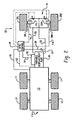
- the HFWD system 33 includes left and right front drive wheels 35L and 35R, driven by hydraulic motors 37L and 37R, respectively, by means of axle shafts 38L and 38R, respectively.
- the motors 37L and 37R receive pressurized fluid from a variable displacement pump 39 (see also FIG. 1).
- the pump 39 receives input drive torque from the engine 13, by means of an input shaft 40 (shown only in FIG. 1), in a manner well known to those skilled in the art.
- valve assembly Disposed between the pump 39 and the motors 37L and 37R is a valve assembly, shown only schematically herein, and generally designated 41, and which forms no part of the present invention and will not be described further herein.
- the front wheel drive system 33 is typically manually selected or engaged by the vehicle operator, and on most vehicles having front wheel drive systems, there is an appropriate "lock-out” feature, whereby the system 33 can be engaged at any time, except when the transmission is in neutral, or when the clutch is depressed (disengaged).
- a steering wheel 43 is disposed in the operator's compartment or cab 27 .
- This is typically accomplished by the use of a full fluid-linked steering control unit of the type sold commercially by the assignee of the present invention, but which forms no part of the invention, and will not be described further herein.
- an HFWD control 49 which would typically comprise a vehicle microprocessor, and be located in the operator's compartment 27, and which transmits and receives various electrical signals to and from both the pump 39 and the valve assembly 41, as will be described in greater detail subsequently.
- the logic includes a number of inputs, which will be described, and the ultimate purpose of the logic is to generate a pump displacement command signal 51, to be transmitted to a controller 52 which, by way of example only, may be an electro-hydraulic control, operable to vary the stroke (displacement) of the pump 39 in response to variations in the command signal 51.
- a controller 52 which, by way of example only, may be an electro-hydraulic control, operable to vary the stroke (displacement) of the pump 39 in response to variations in the command signal 51.
- An important aspect of the present invention is to vary the displacement of the pump 39 in a manner which continuously compensates for any leakage in the system, so that the desired torque of the front drive wheels 35L and 35R may be maintained.
- variable displacement pump 39 provides pressurized fluid to the hydraulic motors 37L and 37R by means of a pair of conduits 53 and 55, and schematically, there is shown a pump pressure sensor 57, in communication with the conduit 53, which is operable to transmit a pump pressure signal 59 to the HFWD control 49.
- a pump speed sensor 61 (shown only in FIG. 3) transmits a pump speed signal 63 to the control 49.
- a sensor measures the speed of the rear wheels 17, and transmits a corresponding rear wheel speed signal 65 to the control 49, and specifically, to an operation block 67 in which the logic, by knowing the displacement (flow volume) of the hydraulic motors 37L and 37R, and steering angles and vehicle geometries, is able to generate a signal 69 representative of anticipated motor flow. It should be understood that the signal 69 represents only "theoretical" motor flow, i.e., the flow which would be required to drive the hydraulic motors 37L and 37R at the same speed as the rear wheels 17, if there were no leakage in the system. Information regarding the geometry of the vehicle steering system, as well as the instantaneous steering angle, are additional inputs to the operation block 67, although not shown in FIG. 3.
- a pair of sensors (not shown in the drawings) which generate a pair of front wheel speed signals 71L and 71R which are transmitted to an operation block 73 which, again based on knowing the displacement of the hydraulic motors 37L and 37R, determines a signal 75 representative of actual motor flow.
- the front wheel speed signals 71L and 71R may be different, but in that case, the signal 75 will represent the sum of the flows to the motors 37L and 37R.
- One other input to the HFWD control 49 is a pressure command signal 77, which is typically the result of a manual input, shown schematically at 78, by the vehicle operator.
- the signal 77 is transmitted to a summing junction 79 where the pump pressure signal 59 is compared to the pressure command signal 77, and an error signal 81 is generated, representative of the difference between the signals 59 and 77.
- the error signal 81 is then transmitted to an operation block 83, which applies a predetermined gain to the error signal 81, then transmits an amplified signal 85 to a summing junction 87, as one of its inputs, the other input to which will be described subsequently.
- the output of the summing junction 87 is transmitted to an operation block 89 in which the output of the summing junction 87 is divided by the pump speed signal 63, thus effectively generating a pump displacement signal 91.
- the signal 91 is then transmitted to an operation block 93 in which the signal 91 is compared to predetermined maximum and minimum limits on the displacement permitted for the variable displacement pump 39.
- the operation block 93 insures that the control 49 does not attempt to command a pump displacement less than the minimum displacement limit or greater than the maximum displacement limit.
- the output of the block 93 is a signal 95 which is transmitted to an operation block 97, in which an appropriate gain is applied, then which generates the pump displacement command signal 51.
- the operation block 97 transmits a signal 99, representative of commanded pump displacement, to a multiplier 101, the other input to the multiplier 101 being the pump speed signal 63.
- the multiplier 101 multiplies the command signal 99 and the pump speed signal 63, and provides an output signal 103 representative of the instantaneous flow from the pump 39.
- the signal 103 is transmitted to a summing junction 105, the other input to which is the signal 75 representative of actual total flow to the motors 37L and 37R.
- the summing junction 105 is able to generate a signal 107 representative of the instantaneous leakage in the system 33.
- leakage is assumed to be proportional to actual pump pressure, as represented by the signal 59.
- the leakage signal 107 is transmitted to an operation block 109 which is a "filter” operable to convert the instantaneous leakage signal 107 and the pump pressure signal 59 into a signal 111 which represents the leakage "gain" for the system.
- the filter calculations are done only if the pump pressure is more than a minimum amount, but less than the relief setting for the system.
- the leakage gain signal 111 is transmitted to a summing junction 113 which has, as its other input, the pressure command signal 77.
- the summing junction 113 multiplies the signal 77 and the signal 111 and generates a signal 115 representative of an adjustment in the pump displacement which is needed to compensate for leakage.
- the signal 115 is transmitted to a summing junction 117 which adds the signal 115 to the signal 69, representative of anticipated motor flow.
- the summing junction 117 generates an output signal 119 and transmits it as the other input to the summing junction 87, described previously.
- the summing junction 87 is adding a signal (85) representative of a pump pressure "error" and a signal (119) representative of anticipated flow, adjusted for instantaneous leakage. As explained previously, the sum of the signals 85 and 119 is then utilized to generate the pump displacement command signal 51.
- the necessary pump displacement, as commanded by the signal 51 is calculated primarily through the use of a feed-forward term, and to a much lesser degree, through the use of feedback terms, i.e., measured pump pressure and motor speeds. This is accomplished by having a smaller value for the constant K in the operation block 83, and by using a fairly large time constant in the filter 109.
Landscapes
- Engineering & Computer Science (AREA)
- General Engineering & Computer Science (AREA)
- Mechanical Engineering (AREA)
- Structural Engineering (AREA)
- Civil Engineering (AREA)
- Chemical & Material Sciences (AREA)
- Mining & Mineral Resources (AREA)
- Physics & Mathematics (AREA)
- Combustion & Propulsion (AREA)
- Analytical Chemistry (AREA)
- Transportation (AREA)
- Fluid Mechanics (AREA)
- Control Of Fluid Gearings (AREA)
- Arrangement And Driving Of Transmission Devices (AREA)
- Motor Power Transmission Devices (AREA)
- Control Of Driving Devices And Active Controlling Of Vehicle (AREA)
- Control Of Vehicle Engines Or Engines For Specific Uses (AREA)
Applications Claiming Priority (2)
| Application Number | Priority Date | Filing Date | Title |
|---|---|---|---|
| US195496 | 1998-11-18 | ||
| US09/195,496 US6164402A (en) | 1998-11-18 | 1998-11-18 | Control of pump for hydraulic front wheel drive |
Publications (3)
| Publication Number | Publication Date |
|---|---|
| EP1002685A2 EP1002685A2 (en) | 2000-05-24 |
| EP1002685A3 EP1002685A3 (en) | 2001-03-28 |
| EP1002685B1 true EP1002685B1 (en) | 2007-01-31 |
Family
ID=22721626
Family Applications (1)
| Application Number | Title | Priority Date | Filing Date |
|---|---|---|---|
| EP99122704A Expired - Lifetime EP1002685B1 (en) | 1998-11-18 | 1999-11-15 | Control of pump for hydraulic front wheel drive |
Country Status (4)
| Country | Link |
|---|---|
| US (1) | US6164402A (ja) |
| EP (1) | EP1002685B1 (ja) |
| JP (1) | JP4178435B2 (ja) |
| DE (1) | DE69935033T2 (ja) |
Families Citing this family (26)
| Publication number | Priority date | Publication date | Assignee | Title |
|---|---|---|---|---|
| EP1561672B1 (en) * | 2004-02-06 | 2011-05-04 | Caterpillar Inc. | Work machine with steering control |
| US7549498B2 (en) * | 2004-09-28 | 2009-06-23 | Caterpillar Inc. | Control for an all-wheel-drive vehicle |
| CA2588290A1 (en) * | 2004-12-01 | 2006-06-08 | Haldex Hydraulics Corporation | Hydraulic drive system |
| US20070144175A1 (en) * | 2005-03-31 | 2007-06-28 | Sopko Thomas M Jr | Turbocharger system |
| US7076954B1 (en) | 2005-03-31 | 2006-07-18 | Caterpillar Inc. | Turbocharger system |
| JP4851802B2 (ja) * | 2006-02-01 | 2012-01-11 | 日立建機株式会社 | 建設機械の旋回駆動装置 |
| DE102006009063A1 (de) | 2006-02-27 | 2007-08-30 | Liebherr-Werk Nenzing Gmbh, Nenzing | Verfahren sowie Vorrichtung zur Regelung eines hydraulischen Antriebssystems |
| US7798272B2 (en) * | 2006-11-30 | 2010-09-21 | Caterpillar Inc | Systems and methods for controlling slip of vehicle drive members |
| US8002073B2 (en) * | 2008-04-22 | 2011-08-23 | Kanzaki Kokyukoki Mfg. Co., Ltd. | Hydraulic drive working vehicle |
| DE102008027333A1 (de) * | 2008-06-07 | 2009-12-31 | Cnh Baumaschinen Gmbh | Steuerungsanordnung für Fahrzeuge mit hydrostatischem Zusatzantrieb |
| US7967099B2 (en) * | 2008-06-19 | 2011-06-28 | Caterpillar Paving Products Inc. | Method and arrangement of a plurality of propel pumps in a hydrostatically driven compactor |
| US7836967B2 (en) * | 2008-07-28 | 2010-11-23 | Caterpillar Inc | Cooling system packaging arrangement for a machine |
| JP5347867B2 (ja) * | 2009-09-23 | 2013-11-20 | 株式会社アドヴィックス | 車両用ブレーキ制御装置 |
| JP5454893B2 (ja) * | 2009-09-28 | 2014-03-26 | 株式会社アドヴィックス | 制動制御装置と当該制動制御装置に用いられるモータ回転数演算方法 |
| US8473170B2 (en) * | 2010-09-17 | 2013-06-25 | Caterpillar Inc. | Closed loop transmission torque control |
| US8626404B2 (en) * | 2010-11-19 | 2014-01-07 | Caterpillar Inc. | Motor grader wheel slip control for cut to grade |
| DE102011013769A1 (de) * | 2011-03-12 | 2012-09-13 | Robert Bosch Gmbh | Verfahren zum Anfahren eines Fahrzeugs mit hydrostatischem Zusatzantrieb und Fahrzeug mit hydrostatischem Zusatzantrieb |
| EP2785550B1 (en) * | 2011-08-25 | 2018-08-22 | CNH Industrial Italia S.p.A. | Method of using feedforward compensation based on pressure feedback for controlling swash plate angle in a hydrostatic power unit of a continuously variable transmission |
| US9303633B2 (en) | 2012-09-14 | 2016-04-05 | Caterpillar Inc. | Over-speed control system and method |
| US9056624B2 (en) * | 2012-11-14 | 2015-06-16 | Deere & Company | Front wheel drive control |
| US9739273B2 (en) | 2014-05-21 | 2017-08-22 | Caterpillar Inc. | Rotatable component overspeed protection method |
| JP6228513B2 (ja) * | 2014-06-17 | 2017-11-08 | ヤンマー株式会社 | 作業車両 |
| WO2019003762A1 (ja) * | 2017-06-27 | 2019-01-03 | 株式会社小松製作所 | 作業車両、及び、作業車両の制御方法 |
| JP7021210B2 (ja) * | 2017-06-27 | 2022-02-16 | 株式会社小松製作所 | 作業車両、及び、作業車両の制御方法 |
| JP7160539B2 (ja) * | 2018-02-23 | 2022-10-25 | 株式会社小松製作所 | 作業車両及び作業車両の制御方法 |
| CN109162314B (zh) * | 2018-10-30 | 2021-01-08 | 山推工程机械股份有限公司 | 一种推土机用轮边减速装置监控系统及控制方法 |
Family Cites Families (9)
| Publication number | Priority date | Publication date | Assignee | Title |
|---|---|---|---|---|
| US5147010A (en) * | 1990-12-06 | 1992-09-15 | Caterpillar Inc. | Method and apparatus for controlling a supplemental vehicle drive in response to slip in a main vehicle drive |
| US5361208A (en) * | 1990-12-06 | 1994-11-01 | Caterpillar Inc. | Supplemental front wheel drive control system and method |
| US5249422A (en) * | 1991-12-20 | 1993-10-05 | Caterpillar Inc. | Apparatus for calibrating the speed of hydrostatically driven traction motors |
| DE4396170T1 (de) * | 1992-11-24 | 1995-10-05 | Komatsu Mfg Co Ltd | Vierradantriebssystem für Kipplastwagen |
| JP2580485B2 (ja) * | 1994-02-18 | 1997-02-12 | 株式会社小松製作所 | 静油圧−機械式変速機の制御装置 |
| US5687808A (en) * | 1994-03-18 | 1997-11-18 | Nissan Motor Co., Ltd. | Four wheel drive mechanism |
| US5474147A (en) * | 1994-07-15 | 1995-12-12 | Caterpillar Inc. | Slip control in a machine for matching hydraulic pump fluid flow to pump driven supplementary front wheel drive motor fluid flow |
| US5576962A (en) * | 1995-03-16 | 1996-11-19 | Caterpillar Inc. | Control system and method for a hydrostatic drive system |
| US5582007A (en) * | 1995-05-11 | 1996-12-10 | Caterpillar Inc. | Method for smooth hydrostatic pump/motor transitions |
-
1998
- 1998-11-18 US US09/195,496 patent/US6164402A/en not_active Expired - Lifetime
-
1999
- 1999-11-12 JP JP32246499A patent/JP4178435B2/ja not_active Expired - Lifetime
- 1999-11-15 DE DE69935033T patent/DE69935033T2/de not_active Expired - Lifetime
- 1999-11-15 EP EP99122704A patent/EP1002685B1/en not_active Expired - Lifetime
Also Published As
| Publication number | Publication date |
|---|---|
| DE69935033D1 (de) | 2007-03-22 |
| JP4178435B2 (ja) | 2008-11-12 |
| US6164402A (en) | 2000-12-26 |
| EP1002685A3 (en) | 2001-03-28 |
| DE69935033T2 (de) | 2007-06-28 |
| JP2000158977A (ja) | 2000-06-13 |
| EP1002685A2 (en) | 2000-05-24 |
Similar Documents
| Publication | Publication Date | Title |
|---|---|---|
| EP1002685B1 (en) | Control of pump for hydraulic front wheel drive | |
| US5147010A (en) | Method and apparatus for controlling a supplemental vehicle drive in response to slip in a main vehicle drive | |
| US7407034B2 (en) | Method, device and computer program product for controlling the steering of a vehicle | |
| US6062332A (en) | Hydrostatic vehicle drive system having improved control thereof | |
| US20050177291A1 (en) | Work machine with steering control | |
| JPH05248529A (ja) | 静水駆動牽引モータの速度較正装置及び方法 | |
| US6578358B1 (en) | Motion stop control for vehicle | |
| US9046160B2 (en) | Control system for differential of machine | |
| US5361208A (en) | Supplemental front wheel drive control system and method | |
| US5975224A (en) | Method for controlling steering in a hydrostatic drive system having differential steer | |
| US4027738A (en) | Device for co-ordinated driving of a towing vehicle and a towed vehicle | |
| US5857532A (en) | Differential steer system for a machine | |
| EP2121404B1 (en) | A method and a system for controlling an input power | |
| EP1088741B1 (en) | Tracked vehicle steering system with steering pump monitoring | |
| US6138782A (en) | Steering responsive power boost | |
| JP2968558B2 (ja) | トルクコンバータ付き走行作業車両の油圧ポンプ制御装置 | |
| JPS5952308A (ja) | 作業装置装備車輛の半自動操縦システム | |
| JPH03153465A (ja) | 車両の操向制御装置 | |
| JP5047630B2 (ja) | 舵取り制御を有する作業機械 | |
| GB2332407A (en) | Method of providing quick steering changes in a vehicle having both steerable and differentially-driven wheels | |
| JP2007520394A5 (ja) | ||
| JPH0347329A (ja) | スキッドステアローダ | |
| JPH04306172A (ja) | フォークリフト用電気ステアリング装置 |
Legal Events
| Date | Code | Title | Description |
|---|---|---|---|
| PUAI | Public reference made under article 153(3) epc to a published international application that has entered the european phase |
Free format text: ORIGINAL CODE: 0009012 |
|
| AK | Designated contracting states |
Kind code of ref document: A2 Designated state(s): DE FR GB IT |
|
| AX | Request for extension of the european patent |
Free format text: AL;LT;LV;MK;RO;SI |
|
| PUAL | Search report despatched |
Free format text: ORIGINAL CODE: 0009013 |
|
| AK | Designated contracting states |
Kind code of ref document: A3 Designated state(s): AT BE CH CY DE DK ES FI FR GB GR IE IT LI LU MC NL PT SE |
|
| AX | Request for extension of the european patent |
Free format text: AL;LT;LV;MK;RO;SI |
|
| 17P | Request for examination filed |
Effective date: 20010712 |
|
| AKX | Designation fees paid |
Free format text: DE FR GB IT |
|
| GRAP | Despatch of communication of intention to grant a patent |
Free format text: ORIGINAL CODE: EPIDOSNIGR1 |
|
| GRAS | Grant fee paid |
Free format text: ORIGINAL CODE: EPIDOSNIGR3 |
|
| GRAA | (expected) grant |
Free format text: ORIGINAL CODE: 0009210 |
|
| AK | Designated contracting states |
Kind code of ref document: B1 Designated state(s): DE FR GB IT |
|
| REG | Reference to a national code |
Ref country code: GB Ref legal event code: FG4D |
|
| REF | Corresponds to: |
Ref document number: 69935033 Country of ref document: DE Date of ref document: 20070322 Kind code of ref document: P |
|
| ET | Fr: translation filed | ||
| PLBE | No opposition filed within time limit |
Free format text: ORIGINAL CODE: 0009261 |
|
| STAA | Information on the status of an ep patent application or granted ep patent |
Free format text: STATUS: NO OPPOSITION FILED WITHIN TIME LIMIT |
|
| 26N | No opposition filed |
Effective date: 20071101 |
|
| REG | Reference to a national code |
Ref country code: FR Ref legal event code: PLFP Year of fee payment: 17 |
|
| REG | Reference to a national code |
Ref country code: FR Ref legal event code: PLFP Year of fee payment: 18 |
|
| REG | Reference to a national code |
Ref country code: FR Ref legal event code: PLFP Year of fee payment: 19 |
|
| REG | Reference to a national code |
Ref country code: FR Ref legal event code: PLFP Year of fee payment: 20 |
|
| REG | Reference to a national code |
Ref country code: GB Ref legal event code: 732E Free format text: REGISTERED BETWEEN 20181115 AND 20181130 |
|
| PGFP | Annual fee paid to national office [announced via postgrant information from national office to epo] |
Ref country code: DE Payment date: 20181023 Year of fee payment: 20 |
|
| REG | Reference to a national code |
Ref country code: DE Ref legal event code: R082 Ref document number: 69935033 Country of ref document: DE Ref country code: DE Ref legal event code: R081 Ref document number: 69935033 Country of ref document: DE Owner name: EATON INTELLIGENT POWER LIMITED, IE Free format text: FORMER OWNER: EATON CORP., CLEVELAND, OHIO, US |
|
| PGFP | Annual fee paid to national office [announced via postgrant information from national office to epo] |
Ref country code: IT Payment date: 20181023 Year of fee payment: 20 Ref country code: GB Payment date: 20181024 Year of fee payment: 20 Ref country code: FR Payment date: 20181024 Year of fee payment: 20 |
|
| REG | Reference to a national code |
Ref country code: DE Ref legal event code: R071 Ref document number: 69935033 Country of ref document: DE |
|
| REG | Reference to a national code |
Ref country code: GB Ref legal event code: PE20 Expiry date: 20191114 |
|
| PG25 | Lapsed in a contracting state [announced via postgrant information from national office to epo] |
Ref country code: GB Free format text: LAPSE BECAUSE OF EXPIRATION OF PROTECTION Effective date: 20191114 |