EP1002507B1 - Appareil de mesure d'urine - Google Patents
Appareil de mesure d'urine Download PDFInfo
- Publication number
- EP1002507B1 EP1002507B1 EP99121233A EP99121233A EP1002507B1 EP 1002507 B1 EP1002507 B1 EP 1002507B1 EP 99121233 A EP99121233 A EP 99121233A EP 99121233 A EP99121233 A EP 99121233A EP 1002507 B1 EP1002507 B1 EP 1002507B1
- Authority
- EP
- European Patent Office
- Prior art keywords
- valve
- housing
- drip chamber
- urine
- valve plate
- Prior art date
- Legal status (The legal status is an assumption and is not a legal conclusion. Google has not performed a legal analysis and makes no representation as to the accuracy of the status listed.)
- Expired - Lifetime
Links
Images


Classifications
-
- A—HUMAN NECESSITIES
- A61—MEDICAL OR VETERINARY SCIENCE; HYGIENE
- A61B—DIAGNOSIS; SURGERY; IDENTIFICATION
- A61B5/00—Measuring for diagnostic purposes; Identification of persons
- A61B5/20—Measuring for diagnostic purposes; Identification of persons for measuring urological functions restricted to the evaluation of the urinary system
- A61B5/207—Sensing devices adapted to collect urine
- A61B5/208—Sensing devices adapted to collect urine adapted to determine urine quantity, e.g. flow, volume
Definitions
- the invention relates to a Urinmeß réelle and in particular a Urine meter, which has a drip chamber with a Antirefluxventil has.
- Urine gauges are used to absorb urine by a Catheter drains out of a patient's body.
- a Urinmeßös can germs from the environment immigrants who multiply there. These germs can pass through the connecting hose leading to the patient in the Patient body and enter a urinary tract infection cause.
- Urine gauges usually at the confluence of the Connecting hose in the measuring container with a Pasteur'schen Chamber equipped. This consists of a drip chamber with a dropper on the inlet side and an antireflux valve on the outflow side. In the drip chamber is from the Connection hose coming liquid column interrupted. The urine drips from a dropper tip and falls free through the air without wetting the walls of the drip chamber. On Dry pathways can not be caused by pathogens continue to move towards the patient.
- a collection phase (usually one hour) that depends Urine meter perpendicular to the bed of the patient.
- the Measuring container is emptied into the urine bag.
- the Measuring container tilted by more than 90 °.
- the refluxing urine could also include the dripper and the interior walls of the Moisten drip chamber so that the germ barrier would be lifted. To prevent this, it is known at the bottom of the drip chamber to provide an anti-reflux valve.
- An anti-reflux valve in conjunction with a drip chamber is known from DE-PS 25 43 778. This consists of Antirefluxventil from a side opening of the Drip chamber occluding valve flap, by a Holding member is biased in the closed position. The Retaining member and the valve flap form a check valve. This check valve consists of at least two parts, from where the holding member has a complex shape. Therefore, the Production relatively expensive.
- a Urinmeß réelle, in which at the lower end of a measuring chamber a Check valve is provided is known from DE 41 37 074 A1.
- the check valve consists of a Valve plate, which against one at the bottom of the Valve opening provided circumferential valve seat presses. over the mounting of the valve plate and its function will not be Information provided.
- a urine meter according to the preamble of claim 1 is in US-A-4,490,144.
- This urine meter contains a Drip chamber, which is arranged above a Feinmeßhunt. In the drip chamber discharges a dropper. At the bottom of the Drip chamber is a valve serving as a reflux barrier, its valve plate of accumulating liquid against a valve seat is pushed up and closes it. Of the Valve seat is provided on a separate component, which with the lower tube end of the valve chamber is connected.
- US-A-4,846,816 describes a urinary drainage device, in the one inlet pipe with a bag via a valve, the one remindflußsperre forms, is connected.
- the valve contains a Valve plate, which is designed as a freely movable loose part and is guided in the valve housing.
- the valve housing is made also here from two nested pipe parts.
- the invention is based on the object, a urine meter with Drip chamber and anti-reflux valve to create at the risk malfunctions due to retained solids is excluded and which in production and installation easy and inexpensive.
- the urine meter has a valve plate on, which consists of a freely movable loose part. This means that the valve plate is not suspended at any point or firmly attached to other structural parts. It it is a loose moving part.
- the valve plate is a flat plate that does not project from the plane of the plate Approaches or the like. having. The valve plate settles at the bottom against a valve seat, if an external force due to backpressing liquid. In the unloaded Condition is the valve plate from the valve seat removed so that the valve opening is open.
- the valve with the exception of the valve plate, is an integral part a meter housing containing the drip chamber. There are no additional components during assembly to introduce into the housing. The valve plate will only placed in the cavity for this purpose, without that a fixation would be required.
- the meter housing has two composite housing parts. The valve opening and the guide elements are part of the one housing part and a cantilever supporting the valve plate is stock of the other housing part. For the assembly, only the two housing parts joined together with the interposition of the valve plate.
- valve is integrated into the meter housing and is the only one specific accessory requires only the valve plate.
- the parts of the valve housing can be integrally into the measuring housing be integrated, so that a separate production or Assembly is omitted.
- the valve plate is a flat plate that no special three-dimensional shaping needed. Much more it can be punched out of a suitable flat foil material his. It preferably consists of polyester film.
- the Valve plate is relatively stiff and dimensionally stable. It preferably exists made of semi-rigid plastic.
- the valve plate is between lateral guide elements kept loose. This means that the valve plate at no Place a firm connection with the valve body has.
- the Guide elements form a kind of cage in which the Valve plate is movable. They are arranged so that in each possible position the projection of the valve plate the valve opening completely covered.
- the lateral guide elements are preferably made of ribs, which protrude inwards from the wall of the valve housing, wherein the valve housing has a larger cross-section than the Valve opening. This is a large flow area for Available. As a result of the absence elastic tensioning means and due to a large free passage cross-section there is no danger that contained in the urine Solids hinder the function of the valve.
- the cross-sectional area of the valve opening is preferably in order at least 70% larger than the inner cross-section of the dropper. In this way is a sufficient size of the valve opening to prevent clogging.
- the Urinmeß réelle has a measuring container 10, which consists of a Feinmeßhunt 11 and a coarse measuring chamber 12 is made.
- the Feinmeßhunt and the coarse measuring chamber are connected by a web thirteenth separated and by an overflow 14 at the upper end of the bridge 13 interconnected.
- a drip chamber 15 is arranged, in which a coming from the patient inlet hose 16 opens.
- the inlet hose 16 is in a hose fixation 17th attached.
- the inlet hose is glued so that front end a few millimeters into the drip chamber 15 protrudes and forms a dropper 18.
- a ventilation filter 19 is attached, which with the ambient air is in communication.
- the drip chamber 15, the Feinmeßhunt 11 and the coarse measuring chamber 12 are part of one consisting of two housing parts Measuring housing.
- the one housing component 20 forms the Front part and the other housing component 21 forms the Back. Front and back are by a circumferential tongue and groove connection 22 under gluing or Welding connected.
- the tongue and groove connection 22 extends encircling the entire meter housing as well along the interior walls.
- valve housing 24 is formed. This consists of assembled components of the two Housing parts 20,21, each one-piece plastic moldings form.
- the valve housing 24 includes a horizontal partition 25, which forms the bottom wall of the drip chamber 15.
- a horizontal partition 25 which forms the bottom wall of the drip chamber 15.
- the circular valve opening 26 included in the Parting wall 25.
- the lower edge of the valve opening 26 forms the bead-like circumferential valve seat 27.
- a cantilever 28th arranged, belonging to the housing part 20 belonging Front wall 29 protrudes inward and approximately parallel to Intermediate wall 25 runs. This cantilever forms a wing or collecting surface for the valve plate 30th
- the valve plate 30 consists of a plastic film, preferably polyester film. Your specific weight is greater than that of urine. It is a flat punched round plate loose in the valve housing 24th is inserted.
- the valve plate 30 is by lateral Guide elements 31 in the form of ribs extending from the wall of the Valve housing 24 protrude inward, kept centered.
- the Guide elements 31 are, as well as the intermediate wall 25, Part of the rear housing part 21st
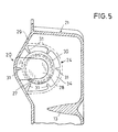
- FIG. 5 shows a view from below into the valve housing 24 the Feinmeßhunt 11 out.
- the radially arranged rib-shaped guide elements 31 visible, of which here six are provided. These guide elements hold the Valve plate 30 in register with the valve seat 27th enclosed valve opening.
- the valve plate 30 is in FIG. 5 not shown in the exact middle position, but laterally added. In any case, it covers the valve opening Completed. From Figure 5 is also seen that the Kragarm 28 only a portion of the surface of the valve plate 30th engages below. Projected over an angular range of more than 270 ° the valve plate 30, the contour of the cantilever 28th
- the intermediate wall 25, the Part of the rear housing part 21 is in a groove 33 inside, which provided on the inside of the front wall 29 is. All guide elements 31 are part of the rearward housing part 21.
- valve housing 24 in which protrude radially the guide elements 31, has a Diameter, which is significantly larger than that of Valve plate 30. Therefore, in the illustrated in Figure 3 Condition in which the valve plate 30 by its weight on the Cantilever 28 rests, liquid along the valve plate 30 along and between the guide elements 31 into the Feinmeßhunt 11 flow.
Landscapes
- Health & Medical Sciences (AREA)
- Life Sciences & Earth Sciences (AREA)
- Medical Informatics (AREA)
- Molecular Biology (AREA)
- Urology & Nephrology (AREA)
- Biophysics (AREA)
- Pathology (AREA)
- Engineering & Computer Science (AREA)
- Biomedical Technology (AREA)
- Heart & Thoracic Surgery (AREA)
- Physiology (AREA)
- Physics & Mathematics (AREA)
- Surgery (AREA)
- Animal Behavior & Ethology (AREA)
- General Health & Medical Sciences (AREA)
- Public Health (AREA)
- Veterinary Medicine (AREA)
- Investigating Or Analysing Biological Materials (AREA)
- Orthopedics, Nursing, And Contraception (AREA)
- Steroid Compounds (AREA)
- Investigating Or Analysing Materials By Optical Means (AREA)
Claims (4)
- Appareil de mesure d'urine, comprenant une chambre compte-gouttes (15) dans laquelle débouche dans un goutte-à-goutte (18) et qui présente une soupape dans le fond, la soupape comprenant une ouverture de soupape (26) présentant un siège de soupape (27) périphérique au niveau de sa face inférieure et une plaque de soupape (30), et la soupape étant reliée à une chambre de mesure de précision (11), caractérisé en ce que la chambre compte-gouttes (15), la chambre de mesure de précision (11) et une chambre de mesure grossière (12) sont configurées dans un carter d'appareil de mesure en deux parties, qui comprend une partie de carter (20) formant une partie avant, et une partie de carter (21) formant une partie arrière, et en ce que l'ouverture de soupape (26) et les éléments de guidage (31) sont des éléments constitutifs de l'une des parties de carter (21) et qu'un bras en porte-à-faux (28) supportant la plaque de soupape (30) est un élément constitutif de l'autre partie de carter (20).
- Appareil de mesure d'urine selon la revendication 1, caractérisé en ce que la plaque de soupape (30) est supportée par un bras en porte-à-faux (28).
- Appareil de mesure d'urine selon la revendication 1 ou 2, caractérisé en ce que les éléments de guidage latéraux (31) sont des nervures saillant depuis la paroi de l'une des parties de carter (21) vers l'intérieur d'un carter de soupape (24) formé par les deux parties de carter, lequel présente une section transversale plus grande que l'ouverture de soupape (26).
- Appareil de mesure d'urine selon l'une quelconque des revendications 1 à 3, caractérisé en ce que la surface de section transversale de l'ouverture de soupape (26) est plus grande d'au moins 70% que la section transversale intérieure du goutte-à-goutte (18).
Applications Claiming Priority (2)
| Application Number | Priority Date | Filing Date | Title |
|---|---|---|---|
| DE29820526U DE29820526U1 (de) | 1998-11-17 | 1998-11-17 | Urinmeßgerät |
| DE29820526U | 1998-11-17 |
Publications (2)
| Publication Number | Publication Date |
|---|---|
| EP1002507A1 EP1002507A1 (fr) | 2000-05-24 |
| EP1002507B1 true EP1002507B1 (fr) | 2003-02-19 |
Family
ID=8065438
Family Applications (1)
| Application Number | Title | Priority Date | Filing Date |
|---|---|---|---|
| EP99121233A Expired - Lifetime EP1002507B1 (fr) | 1998-11-17 | 1999-10-23 | Appareil de mesure d'urine |
Country Status (5)
| Country | Link |
|---|---|
| US (1) | US6348046B2 (fr) |
| EP (1) | EP1002507B1 (fr) |
| AT (1) | ATE232706T1 (fr) |
| DE (2) | DE29820526U1 (fr) |
| ES (1) | ES2188085T3 (fr) |
Families Citing this family (6)
| Publication number | Priority date | Publication date | Assignee | Title |
|---|---|---|---|---|
| WO2008038142A2 (fr) * | 2006-09-28 | 2008-04-03 | Pan, Fei | Drainage du liquide organique d'un patient |
| US8357105B2 (en) * | 2008-08-07 | 2013-01-22 | Covidien Lp | Anti-reflux mechanism for urine collection systems |
| US20120036926A1 (en) * | 2009-02-09 | 2012-02-16 | Pulsion Medical Systems Ag | Device and method for continuously measuring the flow velocity and total volume of a fluid, in particular of urine |
| EP2526907B1 (fr) * | 2011-05-23 | 2013-10-23 | Covidien LP | Mesureur d'urine |
| CN205084081U (zh) * | 2014-11-24 | 2016-03-16 | 胡绍勤 | 一种自动排液引流装置 |
| US20230341975A1 (en) | 2022-04-20 | 2023-10-26 | Apple Inc. | Electronic Devices Having Moisture-Insensitive Optical Touch Sensors |
Family Cites Families (19)
| Publication number | Priority date | Publication date | Assignee | Title |
|---|---|---|---|---|
| US3604420A (en) * | 1969-01-21 | 1971-09-14 | Bard Inc C R | Closed system drainage design |
| US3583401A (en) * | 1969-01-21 | 1971-06-08 | Bard Inc C R | Vented closed drainage system with double lumen tube |
| US3831453A (en) * | 1972-02-10 | 1974-08-27 | Kendall & Co | Urine meter and collection receptacle |
| SE378356B (fr) * | 1973-02-20 | 1975-09-01 | S I Persson | |
| US3965900A (en) | 1974-10-02 | 1976-06-29 | The Kendall Company | Anti-reflux device |
| US3968925A (en) * | 1975-05-12 | 1976-07-13 | Plastronics, Inc. | Anti-reflux valve |
| US4158362A (en) * | 1977-08-23 | 1979-06-19 | Abbott Laboratories | Unidirectionally valved drip chamber, inlet port assembly useful for liquid collection containers |
| US4354492A (en) * | 1979-04-16 | 1982-10-19 | American Hospital Supply Corporation | Medical administration set with backflow check valve |
| US4334537A (en) | 1981-01-28 | 1982-06-15 | The Kendall Company | Drainage receptacle with anti-reflux valve |
| DE3319929A1 (de) * | 1982-06-01 | 1983-12-01 | Urologic and Enteric Research Associates, 60090 Wheeling, Ill. | Mehrkammer-sammelbehaelter |
| US4846816A (en) * | 1982-12-06 | 1989-07-11 | Manfredi Frank A | Male urinary drain system |
| US4490144A (en) * | 1983-02-10 | 1984-12-25 | The Kendall Company | Urine drainage receptacle with a normally open reflux valve |
| US4615693A (en) * | 1984-03-27 | 1986-10-07 | Nypro Inc. | Administration of fluids |
| SE446656B (sv) * | 1985-01-08 | 1986-09-29 | Astra Meditec Ab | Ventilforsedd kopplingsanordning |
| US4743236A (en) * | 1985-05-17 | 1988-05-10 | Plastronics, Inc. | Combination urine meter and urinary drainage bag and the method of use |
| DK158130C (da) * | 1987-11-30 | 1990-09-03 | Uno Plast As | Apparat til opsamling og maaling af legemsvaeske |
| DE4137074A1 (de) * | 1991-11-12 | 1993-05-13 | Hessberg Sigfried Dipl Ing | Messzelle fuer ein geraet zur ueberwachung von aus einem katheter austretender koerperfluessigkeit |
| US5409014A (en) * | 1993-08-13 | 1995-04-25 | Dravon Medical, Inc. | Fluid meter |
| US6254581B1 (en) * | 1998-09-18 | 2001-07-03 | Creighton University | Pleural cavity drainage device |
-
1998
- 1998-11-17 DE DE29820526U patent/DE29820526U1/de not_active Expired - Lifetime
-
1999
- 1999-10-23 EP EP99121233A patent/EP1002507B1/fr not_active Expired - Lifetime
- 1999-10-23 AT AT99121233T patent/ATE232706T1/de not_active IP Right Cessation
- 1999-10-23 ES ES99121233T patent/ES2188085T3/es not_active Expired - Lifetime
- 1999-10-23 DE DE59904318T patent/DE59904318D1/de not_active Expired - Lifetime
- 1999-11-03 US US09/432,227 patent/US6348046B2/en not_active Expired - Fee Related
Also Published As
| Publication number | Publication date |
|---|---|
| US6348046B2 (en) | 2002-02-19 |
| ES2188085T3 (es) | 2003-06-16 |
| EP1002507A1 (fr) | 2000-05-24 |
| ATE232706T1 (de) | 2003-03-15 |
| DE29820526U1 (de) | 2000-04-06 |
| DE59904318D1 (de) | 2003-03-27 |
| US20010016718A1 (en) | 2001-08-23 |
Similar Documents
| Publication | Publication Date | Title |
|---|---|---|
| EP2854891B1 (fr) | Dispositif à récipient de drainage et unité de sac de prélèvement par aspiration | |
| DE2543778C3 (de) | Urinsammelbeutel mit einem auf seiner Innenseite vor einer Einlaßöffnung angeordneten Klappenventil | |
| DE2945379A1 (de) | Vorrichtung zur abfuehrung von fluida aus einer wunde | |
| WO2007085100A2 (fr) | Dispositif de fixation pour récipient de drainage | |
| DE1491739B1 (de) | Vorrichtung zum Ableiten von Fluessigkeiten aus Koerperhohlraeumen | |
| DE2103187B2 (de) | Medizinische Wegwerfvorrichtung zum Absaugen von Flüssigkeiten | |
| DE202005008071U1 (de) | Mobile Harnauffangtasche | |
| DE4127937A1 (de) | Kombiniertes drainage- und autotransfusionsgeraet | |
| EP1002507B1 (fr) | Appareil de mesure d'urine | |
| EP3297701B1 (fr) | Récipient de concentré pour dialyse | |
| DE3127487C2 (de) | Reinigungsrohr | |
| DE2621018A1 (de) | Rueckschlagventil | |
| DE2900806B2 (de) | Vorrichtung zum Sammeln einer Körperflüssigkeit, insbesondere Urin | |
| EP0042499A1 (fr) | Récipient collecteur souple d'une seule pièce à usage médical | |
| DE3106488A1 (de) | Tropfkammer in einem ableitungssystem fuer koerpersekret, insbesondere urin | |
| EP1428771A1 (fr) | Récipient à ordures | |
| DE3202149C2 (de) | Sammelbehälter für Abwasser | |
| DE431949C (de) | Monatsbinde | |
| EP1725196B1 (fr) | Poche de drainage | |
| DE3126581C2 (fr) | ||
| EP1872751A2 (fr) | Sac récupérateur d'urine | |
| DE2832499A1 (de) | Toilette | |
| DE102020119977A1 (de) | Geruchsverschluss und faltbares Ausgussbecken | |
| DE3022555C2 (de) | Zweiraum-Melkbecher | |
| WO2020043817A1 (fr) | Dispositif de drainage et ensemble de drainage |
Legal Events
| Date | Code | Title | Description |
|---|---|---|---|
| PUAI | Public reference made under article 153(3) epc to a published international application that has entered the european phase |
Free format text: ORIGINAL CODE: 0009012 |
|
| AK | Designated contracting states |
Kind code of ref document: A1 Designated state(s): AT BE CH CY DE DK ES FI FR GB GR IE IT LI LU MC NL PT SE |
|
| AX | Request for extension of the european patent |
Free format text: AL;LT;LV;MK;RO;SI |
|
| 17P | Request for examination filed |
Effective date: 20000707 |
|
| AKX | Designation fees paid |
Free format text: AT BE CH CY DE DK ES FI FR GB GR IE IT LI LU MC NL PT SE |
|
| 17Q | First examination report despatched |
Effective date: 20011008 |
|
| GRAG | Despatch of communication of intention to grant |
Free format text: ORIGINAL CODE: EPIDOS AGRA |
|
| GRAG | Despatch of communication of intention to grant |
Free format text: ORIGINAL CODE: EPIDOS AGRA |
|
| GRAH | Despatch of communication of intention to grant a patent |
Free format text: ORIGINAL CODE: EPIDOS IGRA |
|
| GRAH | Despatch of communication of intention to grant a patent |
Free format text: ORIGINAL CODE: EPIDOS IGRA |
|
| GRAA | (expected) grant |
Free format text: ORIGINAL CODE: 0009210 |
|
| AK | Designated contracting states |
Designated state(s): AT BE CH CY DE DK ES FI FR GB GR IE IT LI LU MC NL PT SE |
|
| PG25 | Lapsed in a contracting state [announced via postgrant information from national office to epo] |
Ref country code: NL Free format text: LAPSE BECAUSE OF FAILURE TO SUBMIT A TRANSLATION OF THE DESCRIPTION OR TO PAY THE FEE WITHIN THE PRESCRIBED TIME-LIMIT Effective date: 20030219 Ref country code: IE Free format text: LAPSE BECAUSE OF FAILURE TO SUBMIT A TRANSLATION OF THE DESCRIPTION OR TO PAY THE FEE WITHIN THE PRESCRIBED TIME-LIMIT Effective date: 20030219 Ref country code: GR Free format text: LAPSE BECAUSE OF FAILURE TO SUBMIT A TRANSLATION OF THE DESCRIPTION OR TO PAY THE FEE WITHIN THE PRESCRIBED TIME-LIMIT Effective date: 20030219 Ref country code: FI Free format text: LAPSE BECAUSE OF FAILURE TO SUBMIT A TRANSLATION OF THE DESCRIPTION OR TO PAY THE FEE WITHIN THE PRESCRIBED TIME-LIMIT Effective date: 20030219 |
|
| REG | Reference to a national code |
Ref country code: CH Ref legal event code: EP |
|
| REG | Reference to a national code |
Ref country code: IE Ref legal event code: FG4D Free format text: GERMAN |
|
| REF | Corresponds to: |
Ref document number: 59904318 Country of ref document: DE Date of ref document: 20030327 Kind code of ref document: P |
|
| PG25 | Lapsed in a contracting state [announced via postgrant information from national office to epo] |
Ref country code: SE Free format text: LAPSE BECAUSE OF FAILURE TO SUBMIT A TRANSLATION OF THE DESCRIPTION OR TO PAY THE FEE WITHIN THE PRESCRIBED TIME-LIMIT Effective date: 20030519 Ref country code: PT Free format text: LAPSE BECAUSE OF FAILURE TO SUBMIT A TRANSLATION OF THE DESCRIPTION OR TO PAY THE FEE WITHIN THE PRESCRIBED TIME-LIMIT Effective date: 20030519 Ref country code: DK Free format text: LAPSE BECAUSE OF FAILURE TO SUBMIT A TRANSLATION OF THE DESCRIPTION OR TO PAY THE FEE WITHIN THE PRESCRIBED TIME-LIMIT Effective date: 20030519 |
|
| REG | Reference to a national code |
Ref country code: ES Ref legal event code: FG2A Ref document number: 2188085 Country of ref document: ES Kind code of ref document: T3 |
|
| GBT | Gb: translation of ep patent filed (gb section 77(6)(a)/1977) | ||
| ET | Fr: translation filed | ||
| NLV1 | Nl: lapsed or annulled due to failure to fulfill the requirements of art. 29p and 29m of the patents act | ||
| REG | Reference to a national code |
Ref country code: IE Ref legal event code: FD4D Ref document number: 1002507E Country of ref document: IE |
|
| PG25 | Lapsed in a contracting state [announced via postgrant information from national office to epo] |
Ref country code: LU Free format text: LAPSE BECAUSE OF NON-PAYMENT OF DUE FEES Effective date: 20031023 Ref country code: CY Free format text: LAPSE BECAUSE OF FAILURE TO SUBMIT A TRANSLATION OF THE DESCRIPTION OR TO PAY THE FEE WITHIN THE PRESCRIBED TIME-LIMIT Effective date: 20031023 Ref country code: AT Free format text: LAPSE BECAUSE OF NON-PAYMENT OF DUE FEES Effective date: 20031023 |
|
| PG25 | Lapsed in a contracting state [announced via postgrant information from national office to epo] |
Ref country code: MC Free format text: LAPSE BECAUSE OF NON-PAYMENT OF DUE FEES Effective date: 20031031 Ref country code: LI Free format text: LAPSE BECAUSE OF NON-PAYMENT OF DUE FEES Effective date: 20031031 Ref country code: CH Free format text: LAPSE BECAUSE OF NON-PAYMENT OF DUE FEES Effective date: 20031031 Ref country code: BE Free format text: LAPSE BECAUSE OF NON-PAYMENT OF DUE FEES Effective date: 20031031 |
|
| PLBE | No opposition filed within time limit |
Free format text: ORIGINAL CODE: 0009261 |
|
| STAA | Information on the status of an ep patent application or granted ep patent |
Free format text: STATUS: NO OPPOSITION FILED WITHIN TIME LIMIT |
|
| 26N | No opposition filed |
Effective date: 20031120 |
|
| BERE | Be: lapsed |
Owner name: B. *BRAUN MELSUNGEN A.G. Effective date: 20031031 |
|
| REG | Reference to a national code |
Ref country code: CH Ref legal event code: PL |
|
| REG | Reference to a national code |
Ref country code: FR Ref legal event code: PLFP Year of fee payment: 17 |
|
| REG | Reference to a national code |
Ref country code: FR Ref legal event code: PLFP Year of fee payment: 18 |
|
| REG | Reference to a national code |
Ref country code: FR Ref legal event code: PLFP Year of fee payment: 19 |
|
| REG | Reference to a national code |
Ref country code: FR Ref legal event code: PLFP Year of fee payment: 20 |
|
| PGFP | Annual fee paid to national office [announced via postgrant information from national office to epo] |
Ref country code: DE Payment date: 20181024 Year of fee payment: 20 |
|
| PGFP | Annual fee paid to national office [announced via postgrant information from national office to epo] |
Ref country code: FR Payment date: 20181023 Year of fee payment: 20 Ref country code: GB Payment date: 20181025 Year of fee payment: 20 Ref country code: IT Payment date: 20181022 Year of fee payment: 20 Ref country code: ES Payment date: 20181122 Year of fee payment: 20 |
|
| REG | Reference to a national code |
Ref country code: DE Ref legal event code: R071 Ref document number: 59904318 Country of ref document: DE |
|
| REG | Reference to a national code |
Ref country code: GB Ref legal event code: PE20 Expiry date: 20191022 |
|
| PG25 | Lapsed in a contracting state [announced via postgrant information from national office to epo] |
Ref country code: GB Free format text: LAPSE BECAUSE OF EXPIRATION OF PROTECTION Effective date: 20191022 |
|
| REG | Reference to a national code |
Ref country code: ES Ref legal event code: FD2A Effective date: 20200723 |
|
| PG25 | Lapsed in a contracting state [announced via postgrant information from national office to epo] |
Ref country code: ES Free format text: LAPSE BECAUSE OF EXPIRATION OF PROTECTION Effective date: 20191024 |