EP1001320B1 - Procédé pour l' identification d' un processus avec retard utilisant une compensation et dispositif pour la commande d' un tel processus - Google Patents
Procédé pour l' identification d' un processus avec retard utilisant une compensation et dispositif pour la commande d' un tel processus Download PDFInfo
- Publication number
- EP1001320B1 EP1001320B1 EP99121797A EP99121797A EP1001320B1 EP 1001320 B1 EP1001320 B1 EP 1001320B1 EP 99121797 A EP99121797 A EP 99121797A EP 99121797 A EP99121797 A EP 99121797A EP 1001320 B1 EP1001320 B1 EP 1001320B1
- Authority
- EP
- European Patent Office
- Prior art keywords
- controller
- variable
- controlled variable
- model
- value
- Prior art date
- Legal status (The legal status is an assumption and is not a legal conclusion. Google has not performed a legal analysis and makes no representation as to the accuracy of the status listed.)
- Expired - Lifetime
Links
Images


Classifications
-
- G—PHYSICS
- G05—CONTROLLING; REGULATING
- G05B—CONTROL OR REGULATING SYSTEMS IN GENERAL; FUNCTIONAL ELEMENTS OF SUCH SYSTEMS; MONITORING OR TESTING ARRANGEMENTS FOR SUCH SYSTEMS OR ELEMENTS
- G05B17/00—Systems involving the use of models or simulators of said systems
- G05B17/02—Systems involving the use of models or simulators of said systems electric
-
- B—PERFORMING OPERATIONS; TRANSPORTING
- B29—WORKING OF PLASTICS; WORKING OF SUBSTANCES IN A PLASTIC STATE IN GENERAL
- B29C—SHAPING OR JOINING OF PLASTICS; SHAPING OF MATERIAL IN A PLASTIC STATE, NOT OTHERWISE PROVIDED FOR; AFTER-TREATMENT OF THE SHAPED PRODUCTS, e.g. REPAIRING
- B29C48/00—Extrusion moulding, i.e. expressing the moulding material through a die or nozzle which imparts the desired form; Apparatus therefor
- B29C48/25—Component parts, details or accessories; Auxiliary operations
- B29C48/92—Measuring, controlling or regulating
-
- G—PHYSICS
- G05—CONTROLLING; REGULATING
- G05B—CONTROL OR REGULATING SYSTEMS IN GENERAL; FUNCTIONAL ELEMENTS OF SUCH SYSTEMS; MONITORING OR TESTING ARRANGEMENTS FOR SUCH SYSTEMS OR ELEMENTS
- G05B13/00—Adaptive control systems, i.e. systems automatically adjusting themselves to have a performance which is optimum according to some preassigned criterion
- G05B13/02—Adaptive control systems, i.e. systems automatically adjusting themselves to have a performance which is optimum according to some preassigned criterion electric
- G05B13/04—Adaptive control systems, i.e. systems automatically adjusting themselves to have a performance which is optimum according to some preassigned criterion electric involving the use of models or simulators
- G05B13/042—Adaptive control systems, i.e. systems automatically adjusting themselves to have a performance which is optimum according to some preassigned criterion electric involving the use of models or simulators in which a parameter or coefficient is automatically adjusted to optimise the performance
-
- B—PERFORMING OPERATIONS; TRANSPORTING
- B29—WORKING OF PLASTICS; WORKING OF SUBSTANCES IN A PLASTIC STATE IN GENERAL
- B29C—SHAPING OR JOINING OF PLASTICS; SHAPING OF MATERIAL IN A PLASTIC STATE, NOT OTHERWISE PROVIDED FOR; AFTER-TREATMENT OF THE SHAPED PRODUCTS, e.g. REPAIRING
- B29C2948/00—Indexing scheme relating to extrusion moulding
- B29C2948/92—Measuring, controlling or regulating
- B29C2948/92009—Measured parameter
- B29C2948/92066—Time, e.g. start, termination, duration or interruption
-
- B—PERFORMING OPERATIONS; TRANSPORTING
- B29—WORKING OF PLASTICS; WORKING OF SUBSTANCES IN A PLASTIC STATE IN GENERAL
- B29C—SHAPING OR JOINING OF PLASTICS; SHAPING OF MATERIAL IN A PLASTIC STATE, NOT OTHERWISE PROVIDED FOR; AFTER-TREATMENT OF THE SHAPED PRODUCTS, e.g. REPAIRING
- B29C2948/00—Indexing scheme relating to extrusion moulding
- B29C2948/92—Measuring, controlling or regulating
- B29C2948/92504—Controlled parameter
- B29C2948/92704—Temperature
-
- B—PERFORMING OPERATIONS; TRANSPORTING
- B29—WORKING OF PLASTICS; WORKING OF SUBSTANCES IN A PLASTIC STATE IN GENERAL
- B29C—SHAPING OR JOINING OF PLASTICS; SHAPING OF MATERIAL IN A PLASTIC STATE, NOT OTHERWISE PROVIDED FOR; AFTER-TREATMENT OF THE SHAPED PRODUCTS, e.g. REPAIRING
- B29C2948/00—Indexing scheme relating to extrusion moulding
- B29C2948/92—Measuring, controlling or regulating
- B29C2948/92819—Location or phase of control
- B29C2948/9298—Start-up, shut-down or parameter setting phase; Emergency shut-down; Material change; Test or laboratory equipment or studies
-
- B—PERFORMING OPERATIONS; TRANSPORTING
- B29—WORKING OF PLASTICS; WORKING OF SUBSTANCES IN A PLASTIC STATE IN GENERAL
- B29C—SHAPING OR JOINING OF PLASTICS; SHAPING OF MATERIAL IN A PLASTIC STATE, NOT OTHERWISE PROVIDED FOR; AFTER-TREATMENT OF THE SHAPED PRODUCTS, e.g. REPAIRING
- B29C48/00—Extrusion moulding, i.e. expressing the moulding material through a die or nozzle which imparts the desired form; Apparatus therefor
- B29C48/03—Extrusion moulding, i.e. expressing the moulding material through a die or nozzle which imparts the desired form; Apparatus therefor characterised by the shape of the extruded material at extrusion
- B29C48/12—Articles with an irregular circumference when viewed in cross-section, e.g. window profiles
Definitions
- the invention relates to a method for identifying a delayed process with compensation according to the generic term of claim 1 and a device for regulation of such a process according to the preamble of the claim Third
- a method for regulating the thickness of a through is known from the publication EP 0 542 177 Ejection of formed film is known, the controlled system is subject to delays and has a plurality of actuators for heating the process.
- VZ2 model parameters calculated.
- the process is with that identified and a suitable controller can be designed become.
- the proposed identification procedure is for Processes designed with only one actuator. In processes with several actuators, for example a temperature control with heating and cooling, it cannot can be easily applied.
- the value c g is recorded as an equivalent value and stored.
- a PI structure of the linear controller R is now set, and the parameters of the PI controller are determined using the IT1 model.
- the reset time T n1 of the PI controller is two to ten times, preferably six times, the time constant T 1 .
- the switch from controlled to regulated operation takes place bumpless by the I component of a PI or PID controller initialized accordingly when switching.
- control deviation is below a predetermined limit and / or the gradient of the controlled variable is less than a fraction the slope of the turn tangent WT.
- a PT2 model is preferably used for process identification.
- T 2 t a f -f f-1 .
- t a t u 1 f -f f-1 (1 + f + f ln f f - 1 ) - 1 ,
- a PI or PID controller is designed with this PT2 model.
- plastic extruders used in plastics processing, especially the manufacture of Plastic profiles.
- PVC profiles for window frames can be produced.
- plastic extruders are used for temperature control divided into several zones.
- Plastic granulate fed to a first zone and over Extruder screws conveyed through further heating and cooling zones.
- the plastic receives its product-specific in a nozzle Shape by going through the nozzle with high pressure corresponding contour is pressed through.
- Individual zones of the extruder for example the first zone, can only be heated be while other zones both with heating are also provided with cooling. Temperatures measured in the zones via thermocouples.
- actuators pulse-controlled electrical ones are used for heating Resistors on heating coils or hot plates, as cooling can For example, an adjustable blower can be used.
- temperature zones must either be heated or be cooled since the plastic melted at the beginning must be, but later by operating the system with the Extrusion screw high friction energies are released.
- the effects of frictional heat on temperature can be modeled by a fault at the process input.
- PI or PID controller that regulates the temperature of a Zone can be provided should have good interference behavior at a constant setpoint, so Faults that affect the process as quickly as possible be corrected. Because of this "sharp" attitude however, overshoots occur when the setpoint changes, which in many cases cannot be tolerated with temperature controls are.
- the invention has for its object a method for Identification of a delayed process with Compensation and a device for regulating such Creating process which is the identification enable a process with several actuators.
- the invention has the advantage that it is time-consuming No jump attempt when commissioning a controller can be. With little effort, the dynamic behavior of the process and the respective process reinforcement for the individual actuators determined.
- the new control device fits without manual parameterization and without previous knowledge via the process to any delayed person Processes with compensation. Optimizing the control system can be used for the first time after installation in the control loop without input the operator would be required.
- the invention also has the advantage that for implementation components of a standard controller can be used can.
- the new control device can be interpreted as cascade control become.
- a subordinate control loop one becomes sluggish Temperature range with a P controller or advantageously one PD controller made faster.
- This subordinate control loop is stationary precisely by a superimposed I controller regulated the setpoint.
- This structural breakdown shows in the Practice a bumpless increase in the after a setpoint jump Control variable with a structure change compared to the known one slightly longer rise time, but finally reaches the steady state at the setpoint faster.
- the optimization shows that a loop gain of 21.4 must be set for the subordinate control loop for different processes.
- the smaller time constant of the VZ2 model is chosen as the second time constant t 2 .
- the lower-level control loop advantageously has a complex, well-damped pole pair for all lines.
- the damping is about 0.9 and is therefore close to the asymptotic limit case with damping 1.
- a major advantage of the shown dismantling of a PID controller is that the lower-level control loop with the transfer function G pd for a typical temperature range is about 20 times faster when the unregulated process G reacts to changes.
- auxiliary variable ⁇ id should be limited to a minimum value of 3.5.
- a simple P controller can also be used, which then generates a manipulated variable y p from the controlled variable x.
- the structure shown in FIG. 1 is again used, with only the output variable y pd of the previous PD controller being replaced by the new output variable y p .
- the design of a PI controller disassembled in the manner shown is carried out in an analogous manner according to the scheme already described, so that it is sufficient to state the resulting setting formulas.
- ⁇ ip -5.10414 ⁇ 10 -6 ⁇ F 4 +0.000487705f. 3 - 0.0168150 ⁇ f 2 + 0.263083 * f + 1.13409.
- the structure breakdown shown of a PI or PID controller has the advantage over the known structure switchover that faster readjustment times, especially in the case of abrupt ones Disruptions and with exactly overshoot-free behavior, let it be realized.
- the known structure switchover is generated a jump in the manipulated variable and a very quick one Starting behavior.
- the control loop needs with the known structure switching some time for the final Settling to the setpoint.
- a PI or PID controller with shows a bumpless increase in Control variable with a slightly longer rise time, reached but finally the steady state at the setpoint more quickly.
- a major advantage of structural decomposition is however, that a structural change with interventions in the controller can be dispensed with during operation can. So the new controller with structural decomposition is also in processes with two actuators, especially one Temperature control system with heating and cooling, can be used with advantage.
- the control device is also advantageous suitable for automatic commissioning, for example with a PC-based controller commissioning procedure, because the structural breakdown when designing a software controller fixed and as permanent parameterization a controller can be loaded.
- FIG. 2 shows the model of a temperature control system with two actuators and an upstream split-range unit 5.
- the model of the temperature control system is subdivided into a model 6 for heating, a model 7 for cooling and a model 8 which serves to output the temperature of the steady state, which is set when the heating and cooling are switched off.
- Models 6 and 7 can, for example, be VZ2 elements with the same time constants, but differ in their amplification.
- Output variables x h , x k and x b of models 6, 7 and 8 are superimposed in a summing element 9, which generates a resulting control variable x pr '.
- the split range unit 5 consists of two characteristic elements 10 and 11.
- the characteristic element 10 If there is a positive value for a manipulated variable y pr 'applied to the split range unit 5, the characteristic element 10 outputs the manipulated variable unchanged to the model 6 for heating , while the characteristic element 11 supplies the value "0" to the model 7 for cooling and thus switches off the cooling.
- the heating element is switched off by the characteristic element 10 and the value of the manipulated variable y pr ', weighted by a factor p, is transferred from the characteristic element 11 to the model 7 for cooling.
- the simplest parameter, which characterizes the different behavior when heating and cooling, is the ratio of the maximum gradient of the controlled variable x pr 'when the heating is switched on to the maximum gradient when the cooling is switched on.
- a steady-state amplification of the cooling cannot be determined easily, since one would have to operate heating and cooling at the same time with known parameters of the heating model.
- an upstream controller due to the split range unit 5, outputs a non-zero manipulated variable y h to the model 6 for heating if the manipulated variable y pr 'is positive, and a non-zero manipulated variable y k to the model 7 for Cooling, if this is negative, there is no value of the manipulated variable y pr 'at which heating and cooling are activated at the same time. In normal operation of a temperature control, this would also be a waste of energy.
- FIG. 3 shows a control loop with a control device, which also contains the parts that lead to an automatic Identification of the process based on the above Model presentation are required. How it works and the design of a controller 30 after process identification were already based on Figure 1, the operation of a Split-range unit 5 described with reference to Figure 2. For the same Parts have the same reference numerals.
- a process 32 is shown in Figure 3 with a heater 33 and Provide cooling 34.
- the temperature of the process is called Process variable x fed back to the controller 30.
- a factor p set to "1" by a control unit 35 so that also negative values of the manipulated variable y by the characteristic element 11 without additional weighting to the cooling 34 of process 32 are output.
- An automatic identification process is initiated by a request signal 36 that the control unit 35 does not have one in FIG shown control unit receives. With a signal 37 the control unit 35 flips a switch 38 so that the Actuating variable y not by the controller 30, but by the Control unit 35 is specified with a signal 39.
- On Request signal 36 can, for example, coincide with the first start-up of the control device at a first step of the command variable w are generated.
- the Control unit 35 sets the manipulated variable with signal 39 y to a constant value +80%, at which 80% of the Heating power can be given to process 32 and cooling 34 is switched off.
- a Turning point in the course of the controlled variable x by the control unit 35 determined and, as already from the beginning mentioned German patent application with the official file number 19722431.8 known, a first IT1 model identified, which is the behavior of the process during the heating process describes at least approximately.
- Ways can consist of a turning tangent wh and the second stationary State a VZ2 model can be determined that the Amplification of the heater 33 and the dynamics of the process 32 describes.
- the split range unit 5 switches off the heater 33 and sets the cooling 34 to 20% of the maximum cooling capacity.
- the value of the control signal is kept constant at this value y LLM_TUN until a turning point in the course of the controlled variable x (see FIG. 4) can be seen.
- a simple and effective identification of the gain during the cooling process is achieved by adopting the IT1 models described above, in deviation from the actual VZ2 model describing the process behavior, during the initial phase of the cooling process as during the initial phase of the heating process.
- control unit 35 parameterizes the I controller 1 and the PD controller 2 of the controller 30 and flips the switch 38, so that the manipulated variable y 'generated in the controller 30 is given to the split range unit 5 as the manipulated variable y.
- time t 7800 s (see FIG. 5).
- the controller 32 heats the process 32 back up to the operating point at the temperature 170 ° C.
- the disturbance z e only causes a brief deflection to approximately 180 ° C. and the controlled variable x already reaches the setpoint 170 ° C. after a short time.
- a process model as shown in FIG. 2 was used in the simulations of the control loop. Model 6 for heating and model 7 for cooling are each VZ2 models with the same dynamics.
- the time constant t 1 was set to 3700 s, the time constant t 2 to 350 s.
- a gain k 5.8788 during heating
- a first time constant t 1 3613 s
- the ratio of the gains k ih : k ik was found to be 0.43, which is sufficiently close to the theoretical ideal value of 0.5.
- the reset time t i1 of the I controller 1 is set to 1098 s
- the gain k pd and the lead time t pd of the PD controller 2 to 3.6402 and 215 s, respectively.
- a binary signal 40 which is sent to the control unit 35 can be set in the control device, whether an identification was made during a cooling process shall be.
- the control device to the particular circumstances of the zones of a Plastic extruders are adapted so that they can also be used for pure heating zones can be used. Which is beneficial since both forms on a plastic extruder, d. H. Zones with heating and cooling and zones with pure heating, occur mixed.
- Cooling process it is advantageous to use the Cooling process to identify the gain of the model for cooling to initiate from the working point.
- the cooling capacity becomes strong because of the ratio of the process temperature influenced to the ambient temperature. If in a plastic extruder different for different plastics Working points may need to be set this dependency through a characteristic element in the signal path of the factor p in Figure 3 can be compensated. In extreme cases, if the process temperature is equal to the ambient temperature, the fan cooling becomes ineffective.
- step responses of the transfer functions G, G pd and G cl calculated above are shown in FIGS. 6, 7 and 8.
- the time scale on the abscissa is the same in each case.
- the step response of the route with the transfer function G only reaches 90% of the stationary final value 6 at about 10,000 s, which corresponds to the gain k of the process.
- FIG. 6 the step response of the route with the transfer function G only reaches 90% of the stationary final value 6 at about 10,000 s, which corresponds to the gain k of the process.
- the lower-level control loop reacts with a PD controller 2 to a unit step of the integral component y i much faster and already reaches 90% of the stationary end value after approx. 1000 s.
- FIGS. 9, 10 and 11 show step responses of transmission elements with the transmission functions G ze , G za or with a transmission function which was determined for comparison with a control circuit using an undismantled PID controller.
- the time t is plotted linearly in seconds on the abscissa of FIGS. 9, 10 and 11.
- the control circuit with a disassembled PID controller reacts to a standard step change of the disturbance variable z e with a deflection of the control variable x that hardly exceeds the value 0.2.
- the disturbance is almost completely corrected after only 2500 s.
- a control device for performing the method can advantageous with an internal sequence control with several Different phases can be realized, which differ in the operating modes distinguish between the control device and the models, which are used as the basis for the process identification.
- the control device can also be used as a hardware circuit or as a computing unit with a program memory, in a suitable operating program has been loaded become.
Landscapes
- Engineering & Computer Science (AREA)
- Physics & Mathematics (AREA)
- General Physics & Mathematics (AREA)
- Automation & Control Theory (AREA)
- Artificial Intelligence (AREA)
- Health & Medical Sciences (AREA)
- Mechanical Engineering (AREA)
- Computer Vision & Pattern Recognition (AREA)
- Evolutionary Computation (AREA)
- Medical Informatics (AREA)
- Software Systems (AREA)
- Feedback Control In General (AREA)
- Electrotherapy Devices (AREA)
- Control Of Heat Treatment Processes (AREA)
Claims (12)
- Procédé pour l'identification d'un processus à retard avec compensation, notamment d'un système régulé de température, le processus (32) étant muni d'au moins un premier élément de réglage (33), notamment pour le chauffage du processus (32), et d'un deuxième élément de réglage (34), notamment pour le refroidissement du processus, qui agissent sur le processus avec des gains différents et qui se superposent l'un à l'autre quant à leurs actions, caractérisé par le fait que
à partir d'un premier état stationnaire, on met la grandeur réglante (y) du premier élément de réglage (33) à une première valeur constante (80 %) et on arrête la grandeur réglante du deuxième élément de réglage (34),
après avoir détecté un premier point d'inflexion dans la courbe de la grandeur réglée (x), on identifie un premier modèle IT1 du processus (32),
on régule le processus en fonction du premier modèle IT1 au moins à proximité d'un deuxième état stationnaire (170 °C) différent du premier état stationnaire,
à l'aide de la tangente d'inflexion (wh) au premier point d'inflexion et à l'aide des valeurs de la grandeur réglante (y) ainsi que de la grandeur réglée (x) dans le premier et dans le deuxième état stationnaire, on identifie un modèle VZ2 qui décrit la dynamique du processus (32) et le gain pour le premier élément de réglage (33),
à partir du deuxième état stationnaire, on arrête le premier élément de réglage (33) et on met la grandeur réglante du deuxième élément de réglage (34) à une deuxième valeur constante (20 %),
après avoir détecté un deuxième point d'inflexion dans la courbe de la grandeur réglée (x), on détermine un gain de processus kik pour le deuxième élément de réglage (34) suivant la formule- dxwk / dt -
- une pente de la tangente (wk) au deuxième point d'inflexion,
- kih -
- un gain de processus du premier modèle IT1 identifié,
- y∞ -
- une valeur de la grandeur réglante (y) délivrée dans le deuxième état stationnaire, et
- YLLM_TUN -
- une deuxième valeur constante de la grandeur réglante.
- Procédé selon la revendication 1, caractérisé par le fait que
le premier élément de réglage (33) est un chauffage et le deuxième élément de réglage (34) est un refroidissement, et
le deuxième état stationnaire (170°C) correspond à un point de fonctionnement typique du processus (32). - Dispositif pour la régulation d'un processus à retard avec compensation, notamment d'une extrudeuse de plastique, le processus (32) étant muni d'au moins un premier élément de réglage (33), notamment pour le chauffage du processus (32), et d'un deuxième élément de réglage (34), notamment pour le refroidissement du processus (32), qui agissent sur le processus (32) avec des gains différents et qui se superposent l'un à l'autre quant à leurs actions,
avec un régulateur (30) qui produit une grandeur réglante (y) à partir d'une différence de régulation (xd) formée à partir d'une grandeur de commande (w) et d'une grandeur réglée (x),
caractérisé par
une unité de commande (35) telle que
à partir d'un premier état stationnaire, la grandeur réglante (y) du premier élément de réglage (33) est mise à une première valeur constante (80 %) et la grandeur réglante du deuxième élément de réglage (34) est arrêtée,
après avoir détecté un premier point d'inflexion dans la courbe de la grandeur réglée (x), un premier modèle IT1 du processus (32) est identifié,
le processus est régulé en fonction du premier modèle IT1 au moins à proximité d'un deuxième état stationnaire (170 °C) différent du premier état stationnaire,
à l'aide de la tangente d'inflexion (wh) au premier point d'inflexion et à l'aide des valeurs de la grandeur réglante (y) ainsi que de la grandeur réglée (x) dans le premier et dans le deuxième état stationnaire, un modèle VZ2 est identifié, lequel décrit la dynamique du processus (32) et le gain pour le premier élément de réglage (33),
à partir du deuxième état stationnaire, le premier élément de réglage (33) est arrêté et la grandeur réglante du deuxième élément de réglage (34) est mise à une deuxième valeur constante (20 %),
après avoir détecté un deuxième point d'inflexion dans la courbe de la grandeur réglée (x), un gain de processus kik pour le deuxième élément de réglage (34) est déterminé suivant la formule- dxwk / dt -
- une pente de la tangente (wk) au deuxième point d'inflexion,
- kih -
- un gain de processus du premier modèle IT1 identifié,
- y∞ -
- une valeur de la grandeur réglante (y) délivrée dans le deuxième état stationnaire, et
- yLLM_TUN -
- une deuxième valeur constante de la grandeur réglante.
- Dispositif selon la revendication 3, caractérisé par un régulateur I (1) qui produit une composante intégrale (yi) à partir d'une différence de régulation (xd) formée à partir d'une grandeur de commande (w) et d'une grandeur réglés (x), par un régulateur P ou PD (2) qui, dans un circuit de régulation subordonné, produit une composante proportionnelle (yp) ou une composante proportionnelle et différentielle (ypd) à partir de la grandeur réglés (x), et par un élément additionneur (3) pour la superposition des composantes (yi, yp, ypd) produites par les régulateurs (1, 2) pour donner une grandeur réglante (y) pour le processus (4).
- Dispositif selon la revendication 4, caractérisé par le fait que
une unité split-range (5) est branchée du côté aval de l'élément additionneur (3) de telle sorte que le domaine de valeurs de la grandeur réglante (y) produite par l'élément additionneur (3) est divisé en deux sous-domaines,
pour une valeur de la grandeur réglante (y) dans un premier sous-domaine (0 à 100 %), une grandeur réglante est délivrée pour un chauffage (33) et un refroidissement (34) est arrêté, et
pour une valeur de la grandeur réglante (y) dans un deuxième sous-domaine (- 100 % à 0), une grandeur réglante est délivrée pour le refroidissement (34) et le chauffage (33) est arrêté. - Dispositif selon la revendication 5, caractérisé par le fait que
le domaine de valeurs de la grandeur réglante produite par l'élément additionneur (3) comprend un sous-domaine positif et un sous-domaine négatif,
pour une valeur de la grandeur réglante dans le sous-domaine positif, la grandeur réglante est délivrée sans changement au chauffage (33), et
pour une valeur de la grandeur réglante dans le sous-domaine négatif, la grandeur réglante (y) est délivrée au refroidissement (34) après une pondération avec un facteur (p) qui correspond au rapport entre le gain kih du chauffage (33) et le gain kik du refroidissement (34). - Dispositif selon l'une des revendications 4 à 6, caractérisé par le fait que, dans le cas d'un régulateur PD (2) dans le circuit de régulation subordonné, le gain kpd et la constante de temps tpd sont calculés par un développement de régulateur selon les méthodes mathématiques de l'optimisation dans l'espace d'états.
- Dispositif selon la revendication 7, caractérisé par le fait que, pour l'optimisation dans l'espace d'états. un critère de qualitéavec
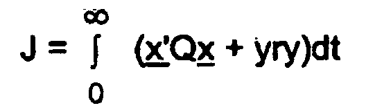
- x' = (x, x•) -
- un vecteur d'état transposé,
- x -
- un vecteur d'état,
- Q -
- une matrice unité,
- y -
- une grandeur réglante, et
- r -
- un facteur de pondération entre 0,0002 et 0,02
- Dispositif selon l'une des revendications 4 à 6, caractérisé par le fait que,
dans le cas d'un régulateur PD (2) dans le circuit de régulation subordonné, le gain kpd et la constante de temps tpd du régulateur (2) sont déterminés au moins approximativement suivant les formules- k -
- un gain du système,
- t1, t2 -
- des constantes de temps du système,
- αd2 -
- une grandeur auxiliaire, et
- f = t1 / t2 -
- un rapport des constantes de temps du système.
- Dispositif selon l'une des revendications 7 à 9, caractérisé par le fait que le temps de compensation ti1 du régulateur I (1) est déterminé au moins approximativement suivant la formule
- f = t1 / t2 -
- un rapport des constantes de temps t1 et t2 du système, et
- tpd -
- une constante de temps du régulateur PD (2).
- Dispositif selon la revendication 4, caractérisé par le fait que,
dans le cas d'un régulateur P dans le circuit de régulation subordonné, le gain kp du régulateur P est déterminé au moins approximativement suivant la formule- f = t1 / t2 -
- un rapport des constantes de temps t1 et t2 du système, et
- k -
- un gain du système.
- Dispositif selon la revendication 11, caractérisé par le fait que le temps de compensation ti2 du régulateur I est déterminé au moins approximativement suivant les formules
- αip -
- une grandeur auxiliaire, et
- tpi -
- une constante de temps du circuit de régulation subordonné fermé.
Applications Claiming Priority (2)
| Application Number | Priority Date | Filing Date | Title |
|---|---|---|---|
| DE19851826A DE19851826A1 (de) | 1998-11-10 | 1998-11-10 | Verfahren zur Identifikation eines verzögerungsbehafteten Prozesses mit Ausgleich sowie Einrichtung zur Regelung eines derartigen Prozesses |
| DE19851826 | 1998-11-10 |
Publications (2)
| Publication Number | Publication Date |
|---|---|
| EP1001320A1 EP1001320A1 (fr) | 2000-05-17 |
| EP1001320B1 true EP1001320B1 (fr) | 2003-06-18 |
Family
ID=7887320
Family Applications (1)
| Application Number | Title | Priority Date | Filing Date |
|---|---|---|---|
| EP99121797A Expired - Lifetime EP1001320B1 (fr) | 1998-11-10 | 1999-11-03 | Procédé pour l' identification d' un processus avec retard utilisant une compensation et dispositif pour la commande d' un tel processus |
Country Status (4)
| Country | Link |
|---|---|
| EP (1) | EP1001320B1 (fr) |
| AT (1) | ATE243331T1 (fr) |
| DE (2) | DE19851826A1 (fr) |
| ES (1) | ES2202990T3 (fr) |
Families Citing this family (5)
| Publication number | Priority date | Publication date | Assignee | Title |
|---|---|---|---|---|
| DE10060125A1 (de) * | 2000-12-04 | 2002-06-13 | Siemens Ag | Verfahren zur Regelung eines verzögerungsbehafteten Prozesses mit Ausgleich sowie Regeleinrichtung zur Durchführung des Verfahrens |
| FR2821175A1 (fr) * | 2001-02-19 | 2002-08-23 | Solvay | Methode de regulation d'une propriete d'un produit resultant d'une transformation chimique |
| US7103445B2 (en) | 2002-11-27 | 2006-09-05 | Kimberly-Clark Worldwide, Inc. | System and method for controlling the dispense rate of particulate material |
| US20100268500A1 (en) * | 2006-10-18 | 2010-10-21 | Lutz Augenstein | Method and device for the identification of a delay-susceptible control path, control device and computer program product |
| CN103713521B (zh) * | 2013-12-31 | 2017-01-11 | 广州市香港科大霍英东研究院 | 一种针对注塑过程区间时滞的2d控制器设计方法 |
Family Cites Families (10)
| Publication number | Priority date | Publication date | Assignee | Title |
|---|---|---|---|---|
| EP0416468A1 (fr) * | 1989-09-04 | 1991-03-13 | Kabushiki Kaisha Toshiba | Moteur refroidi par air pour l'usage dans des véhicules |
| JPH0661811B2 (ja) * | 1989-11-24 | 1994-08-17 | 東芝機械株式会社 | 加熱温度制御装置 |
| DE4026995A1 (de) * | 1990-08-25 | 1992-02-27 | Thomson Brandt Gmbh | Regelkreis |
| DE4120796A1 (de) * | 1991-06-24 | 1993-01-07 | Siemens Ag | Einrichtung zur parameteridentifikation einer uebertragungsstrecke |
| JP3021135B2 (ja) * | 1991-11-12 | 2000-03-15 | 三菱重工業株式会社 | フィルム厚み制御装置 |
| DE4320900C1 (de) * | 1993-06-24 | 1994-09-29 | Kloeckner Moeller Gmbh | Verfahren zur Temperaturregelung mit selbständiger Modellermittlung eines Prozeßverhaltens unter Ausnutzung des Aufheizvorganges und zur Bestimmung des Übertragungsverhaltens des Prozesses |
| DE19525066A1 (de) * | 1995-07-10 | 1997-01-16 | Buna Sow Leuna Olefinverb Gmbh | Verfahren zur Parametrierung und Inbetriebnahme eines prädiktiven Reglers |
| DE29513152U1 (de) * | 1995-08-16 | 1996-09-19 | Siemens AG, 80333 München | Einrichtung zur Identifikation einer Übertragungsstrecke |
| DE19548909A1 (de) * | 1995-12-27 | 1997-07-03 | Siemens Ag | Verfahren zur Regelung eines verzögerungsbehafteten Prozesses mit Ausgleich sowie Regeleinrichtung zur Durchführung des Verfahrens |
| DE19722431A1 (de) * | 1997-05-28 | 1998-12-03 | Siemens Ag | Verfahren zur Regelung eines verzögerungsbehafteten Prozesses mit Ausgleich sowie Regeleinrichtung zur Durchführung des Verfahrens |
-
1998
- 1998-11-10 DE DE19851826A patent/DE19851826A1/de not_active Withdrawn
-
1999
- 1999-11-03 AT AT99121797T patent/ATE243331T1/de not_active IP Right Cessation
- 1999-11-03 ES ES99121797T patent/ES2202990T3/es not_active Expired - Lifetime
- 1999-11-03 DE DE59905989T patent/DE59905989D1/de not_active Expired - Lifetime
- 1999-11-03 EP EP99121797A patent/EP1001320B1/fr not_active Expired - Lifetime
Also Published As
| Publication number | Publication date |
|---|---|
| ATE243331T1 (de) | 2003-07-15 |
| EP1001320A1 (fr) | 2000-05-17 |
| DE59905989D1 (de) | 2003-07-24 |
| ES2202990T3 (es) | 2004-04-01 |
| DE19851826A1 (de) | 2000-05-11 |
Similar Documents
| Publication | Publication Date | Title |
|---|---|---|
| DE4433593B4 (de) | Verfahren zur Regelung eines Extruders und Vorrichtung dazu | |
| DE69511991T2 (de) | Verfahren und Vorrichtung zur Steuerung von Mehrgrössen-/nichtlinearen Systemen | |
| EP0985170B1 (fr) | Procede de regulation d'un processus temporise avec compensation et systeme de regulation permettant de mettre ledit procede en oeuvre | |
| DE69029893T2 (de) | Vorrichtung zur Regelung einer Heiztemperatur | |
| DE19756053B4 (de) | Drosselklappensteuervorrichtung | |
| EP0756219B1 (fr) | Procédé de surveillance des propriétés de produits et procédé de contrôle d'un procédé de fabrication | |
| DE102006002296B3 (de) | Regelsystem sowie Regelverfahren für Spritzgießmaschinen | |
| EP1001320B1 (fr) | Procédé pour l' identification d' un processus avec retard utilisant une compensation et dispositif pour la commande d' un tel processus | |
| WO1992007701A1 (fr) | Procede et dispositif de production d'extrudats plats a section transversale annulaire | |
| EP2288969B1 (fr) | Système de conduite d'une installation avec optimisation du modèle en plusieurs phases | |
| EP0870219B1 (fr) | Procede et dispositif de regulation d'un processus auto-compensateur susceptible de ralentissement | |
| EP1490735B1 (fr) | Procede et regulateur permettant la regulation adaptative d'au moins une composante d'une installation technique | |
| DE69736799T2 (de) | Verfahren zur steuerung eines servomotors | |
| EP3542229B1 (fr) | Dispositif et procédé de détermination des paramètres d'un dispositif de réglage | |
| DE3884542T2 (de) | Adaptive mehrgrössensteuerung. | |
| EP1217472B1 (fr) | Procédé de commande d' un processus avec retard utilisant une compensation et dispositif pour la commande d' un tel procédé | |
| DE19851827A1 (de) | Einrichtung zur Regelung der Temperatur eines technischen Prozesses | |
| DE69114623T2 (de) | Regelungssystem des Typs mit zwei Freiheitsgraden. | |
| DE10226670B4 (de) | Regeleinrichtung und -verfahren | |
| DE4100064A1 (de) | Verfahren und schaltungsanordnung zur vermeidung eines reset-windup-effektes bei einer regelschaltung | |
| DE3418501A1 (de) | Vorrichtung zur praediktiven zeitdiskreten ein-aus-regelung zeitkontinuierlicher prozesse mit binaer wirkenden stellelementen | |
| EP0692752A1 (fr) | Circuit pour un régulateur à retroaction flexible | |
| DE4320900C1 (de) | Verfahren zur Temperaturregelung mit selbständiger Modellermittlung eines Prozeßverhaltens unter Ausnutzung des Aufheizvorganges und zur Bestimmung des Übertragungsverhaltens des Prozesses | |
| WO2000049472A1 (fr) | Regulateur non lineaire | |
| EP0724748B1 (fr) | Dispositif de regulation |
Legal Events
| Date | Code | Title | Description |
|---|---|---|---|
| PUAI | Public reference made under article 153(3) epc to a published international application that has entered the european phase |
Free format text: ORIGINAL CODE: 0009012 |
|
| AK | Designated contracting states |
Kind code of ref document: A1 Designated state(s): AT CH DE ES FR GB LI |
|
| AX | Request for extension of the european patent |
Free format text: AL;LT;LV;MK;RO;SI |
|
| 17P | Request for examination filed |
Effective date: 20000619 |
|
| AKX | Designation fees paid |
Free format text: AT CH DE ES FR GB LI |
|
| GRAH | Despatch of communication of intention to grant a patent |
Free format text: ORIGINAL CODE: EPIDOS IGRA |
|
| GRAH | Despatch of communication of intention to grant a patent |
Free format text: ORIGINAL CODE: EPIDOS IGRA |
|
| GRAA | (expected) grant |
Free format text: ORIGINAL CODE: 0009210 |
|
| AK | Designated contracting states |
Designated state(s): AT CH DE ES FR GB LI |
|
| REG | Reference to a national code |
Ref country code: GB Ref legal event code: FG4D Free format text: NOT ENGLISH |
|
| REG | Reference to a national code |
Ref country code: CH Ref legal event code: EP |
|
| REF | Corresponds to: |
Ref document number: 59905989 Country of ref document: DE Date of ref document: 20030724 Kind code of ref document: P |
|
| REG | Reference to a national code |
Ref country code: CH Ref legal event code: NV Representative=s name: SERVOPATENT GMBH |
|
| GBT | Gb: translation of ep patent filed (gb section 77(6)(a)/1977) |
Effective date: 20031015 |
|
| REG | Reference to a national code |
Ref country code: ES Ref legal event code: FG2A Ref document number: 2202990 Country of ref document: ES Kind code of ref document: T3 |
|
| PLBE | No opposition filed within time limit |
Free format text: ORIGINAL CODE: 0009261 |
|
| STAA | Information on the status of an ep patent application or granted ep patent |
Free format text: STATUS: NO OPPOSITION FILED WITHIN TIME LIMIT |
|
| ET | Fr: translation filed | ||
| 26N | No opposition filed |
Effective date: 20040319 |
|
| PGFP | Annual fee paid to national office [announced via postgrant information from national office to epo] |
Ref country code: ES Payment date: 20081216 Year of fee payment: 10 Ref country code: AT Payment date: 20081017 Year of fee payment: 10 |
|
| REG | Reference to a national code |
Ref country code: CH Ref legal event code: PCAR Free format text: SIEMENS SCHWEIZ AG;INTELLECTUAL PROPERTY FREILAGERSTRASSE 40;8047 ZUERICH (CH) |
|
| PGFP | Annual fee paid to national office [announced via postgrant information from national office to epo] |
Ref country code: CH Payment date: 20090205 Year of fee payment: 10 |
|
| REG | Reference to a national code |
Ref country code: CH Ref legal event code: PL |
|
| PG25 | Lapsed in a contracting state [announced via postgrant information from national office to epo] |
Ref country code: AT Free format text: LAPSE BECAUSE OF NON-PAYMENT OF DUE FEES Effective date: 20091103 |
|
| PG25 | Lapsed in a contracting state [announced via postgrant information from national office to epo] |
Ref country code: LI Free format text: LAPSE BECAUSE OF NON-PAYMENT OF DUE FEES Effective date: 20091130 Ref country code: CH Free format text: LAPSE BECAUSE OF NON-PAYMENT OF DUE FEES Effective date: 20091130 |
|
| REG | Reference to a national code |
Ref country code: ES Ref legal event code: FD2A Effective date: 20110411 |
|
| PG25 | Lapsed in a contracting state [announced via postgrant information from national office to epo] |
Ref country code: ES Free format text: LAPSE BECAUSE OF NON-PAYMENT OF DUE FEES Effective date: 20110330 |
|
| PG25 | Lapsed in a contracting state [announced via postgrant information from national office to epo] |
Ref country code: ES Free format text: LAPSE BECAUSE OF NON-PAYMENT OF DUE FEES Effective date: 20091104 |
|
| PGFP | Annual fee paid to national office [announced via postgrant information from national office to epo] |
Ref country code: FR Payment date: 20141112 Year of fee payment: 16 Ref country code: GB Payment date: 20141110 Year of fee payment: 16 |
|
| PGFP | Annual fee paid to national office [announced via postgrant information from national office to epo] |
Ref country code: DE Payment date: 20150119 Year of fee payment: 16 |
|
| REG | Reference to a national code |
Ref country code: DE Ref legal event code: R119 Ref document number: 59905989 Country of ref document: DE |
|
| GBPC | Gb: european patent ceased through non-payment of renewal fee |
Effective date: 20151103 |
|
| REG | Reference to a national code |
Ref country code: FR Ref legal event code: ST Effective date: 20160729 |
|
| PG25 | Lapsed in a contracting state [announced via postgrant information from national office to epo] |
Ref country code: DE Free format text: LAPSE BECAUSE OF NON-PAYMENT OF DUE FEES Effective date: 20160601 Ref country code: GB Free format text: LAPSE BECAUSE OF NON-PAYMENT OF DUE FEES Effective date: 20151103 |
|
| PG25 | Lapsed in a contracting state [announced via postgrant information from national office to epo] |
Ref country code: FR Free format text: LAPSE BECAUSE OF NON-PAYMENT OF DUE FEES Effective date: 20151130 |