EP1001122A1 - Mehrriegeltreibstangenschloss mit Wechselbetätigung - Google Patents
Mehrriegeltreibstangenschloss mit Wechselbetätigung Download PDFInfo
- Publication number
- EP1001122A1 EP1001122A1 EP99890356A EP99890356A EP1001122A1 EP 1001122 A1 EP1001122 A1 EP 1001122A1 EP 99890356 A EP99890356 A EP 99890356A EP 99890356 A EP99890356 A EP 99890356A EP 1001122 A1 EP1001122 A1 EP 1001122A1
- Authority
- EP
- European Patent Office
- Prior art keywords
- push rod
- bolt
- rod piece
- spring
- driver
- Prior art date
- Legal status (The legal status is an assumption and is not a legal conclusion. Google has not performed a legal analysis and makes no representation as to the accuracy of the status listed.)
- Granted
Links
- 238000006073 displacement reaction Methods 0.000 claims abstract description 7
- 238000004904 shortening Methods 0.000 claims abstract description 4
- 230000007704 transition Effects 0.000 description 2
- 230000005540 biological transmission Effects 0.000 description 1
- 239000000872 buffer Substances 0.000 description 1
- 230000007717 exclusion Effects 0.000 description 1
- 238000003780 insertion Methods 0.000 description 1
- 230000037431 insertion Effects 0.000 description 1
- 238000009434 installation Methods 0.000 description 1
Images
Classifications
-
- E—FIXED CONSTRUCTIONS
- E05—LOCKS; KEYS; WINDOW OR DOOR FITTINGS; SAFES
- E05C—BOLTS OR FASTENING DEVICES FOR WINGS, SPECIALLY FOR DOORS OR WINDOWS
- E05C9/00—Arrangements of simultaneously actuated bolts or other securing devices at well-separated positions on the same wing
- E05C9/02—Arrangements of simultaneously actuated bolts or other securing devices at well-separated positions on the same wing with one sliding bar for fastening when moved in one direction and unfastening when moved in opposite direction; with two sliding bars moved in the same direction when fastening or unfastening
- E05C9/021—Arrangements of simultaneously actuated bolts or other securing devices at well-separated positions on the same wing with one sliding bar for fastening when moved in one direction and unfastening when moved in opposite direction; with two sliding bars moved in the same direction when fastening or unfastening with rack and pinion mechanism
- E05C9/023—Arrangements of simultaneously actuated bolts or other securing devices at well-separated positions on the same wing with one sliding bar for fastening when moved in one direction and unfastening when moved in opposite direction; with two sliding bars moved in the same direction when fastening or unfastening with rack and pinion mechanism between a lock cylinder and the bar
-
- E—FIXED CONSTRUCTIONS
- E05—LOCKS; KEYS; WINDOW OR DOOR FITTINGS; SAFES
- E05B—LOCKS; ACCESSORIES THEREFOR; HANDCUFFS
- E05B15/00—Other details of locks; Parts for engagement by bolts of fastening devices
- E05B15/004—Lost motion connections
-
- E—FIXED CONSTRUCTIONS
- E05—LOCKS; KEYS; WINDOW OR DOOR FITTINGS; SAFES
- E05C—BOLTS OR FASTENING DEVICES FOR WINGS, SPECIALLY FOR DOORS OR WINDOWS
- E05C9/00—Arrangements of simultaneously actuated bolts or other securing devices at well-separated positions on the same wing
- E05C9/18—Details of fastening means or of fixed retaining means for the ends of bars
- E05C9/1825—Fastening means
- E05C9/1833—Fastening means performing sliding movements
- E05C9/185—Fastening means performing sliding movements parallel with actuating bar
-
- E—FIXED CONSTRUCTIONS
- E05—LOCKS; KEYS; WINDOW OR DOOR FITTINGS; SAFES
- E05B—LOCKS; ACCESSORIES THEREFOR; HANDCUFFS
- E05B15/00—Other details of locks; Parts for engagement by bolts of fastening devices
- E05B15/04—Spring arrangements in locks
- E05B2015/0482—Heavy springs which cannot be operated by hand
-
- E—FIXED CONSTRUCTIONS
- E05—LOCKS; KEYS; WINDOW OR DOOR FITTINGS; SAFES
- E05B—LOCKS; ACCESSORIES THEREFOR; HANDCUFFS
- E05B59/00—Locks with latches separate from the lock-bolts or with a plurality of latches or lock-bolts
Definitions
- the invention relates to a multi-bolt lock with change operation and push rod connection to at least one of the Bolt, being between a bolt-side push rod piece and a drive-side push rod piece a driver connection with exemption, in particular on the one hand push rod-fixed driver, on the other hand in an elongated hole engages the other push rod piece is provided.
- DE 38 26 802 A1 relates to an espagnolette lock with locking cylinder that has an espagnolette operated with toothed rack via a pinion. Between the Espagnolette slide and the rack is a relative movement possible to create a movement game. This movement game corresponds in the extension direction of the drive rod the angle of rotation of the locking lug of the locking cylinder from the Installation position in the lock insertion opening until the key is withdrawn.
- a multi-bolt lock has an entirely different requirement meet when it's unlocked, so the bolt from the Striker is withdrawn. It must be with Bolt still uses the bolt drive to actuate the latch respectively. This could be coupled with the bolt retraction be that part of the retraction path of the bars also for the Trap retraction is used, for example in that the latch withdrawn briefly into the interior of the transom housing become and with this drive movement about a change the Trap is actuated. But that's part of the way for the bars were lost.
- the invention aims at a latch actuation dead bolt in its open position which remains unchanged to enable. This is achieved in that the Exemption towards the withdrawal of at least one Riegel is provided. It is useful if a spring is on the driver connection attacks and each with a spring end on each of the push rod pieces, this in the sense prestressing a shortening of their effective total length and if a stop to limit the displacement of the bolt-side push rod piece at complete withdrawn bolt is provided. As a bolt side A locking shaft can also be provided, the via the driver connection with exemption to the drive side Push rod is connected.
- the two Push rod pieces overlap each other and the spring is in the Overlap area provided on supports at the ends the push rod pieces, especially on L-shaped bends, abuts and the ends of the overlap area apart presses. It is also useful if the requirements, especially the L-shaped bends of each push rod piece each guided on the opposite push rod piece and if one of the bends in an elongated hole of the other push rod piece and immersed in this as Driver against the force of the spring limited displacement is. The length of the elongated hole determines the path for the Stroke of the change lever for the latch actuation is necessary. When locking, the spring comes, unlike the state of the Technology, not effective, because of the push rod or their drivers directly in the feed direction (i.e.
- the latch (s) are not moving, however the spring is compressed between the two push rod pieces.
- This displacement path or angle of rotation of the or one of the driving gear wheels is over a Change lever using a pin on the flat side of the aforementioned gear implemented in a stroke that over a Angle lever leads to retraction of the trap.
- the trap will pushed out again by a trap spring.
- the invention Training thus allows a trap operation with the Key as well as with the handle, depending on the design of the Castle.
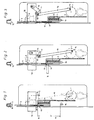
- FIG. 1 shows a multi-bolt lock in a schematic representation in the locked state with the push rod pushed out or bolt
- Fig. 2 shows the lock of FIG. 1 with the retracted Bolt and with change to latch actuation
- Fig. 3 with the lock of FIG. 2 during the change operation dead bolt and trap drawn.
- a multi-bolt lock according to FIG. 1 comprises one of one Lock cylinder with gearbox operated via its locking lug an abortive gear 1 with a locking lug 2 is engaged.
- the rack 2 is part of a drive side Push rod piece 3, which in its end region engages over a bolt-side push rod piece 4. Both push rod pieces 3 and 4 are guided linearly.
- the Push rod piece 4 is at its end remote from the lock with its Bolt 5 connected. Furthermore, the push rod piece 4 a toothing 6, in which a pinion 7 engages, which an oppositely acting push rod 8 moves.
- the ends of the push rod pieces 3, 4 are in the overlap area bent into L-shaped supports.
- the end of the push rod piece 3 forms a driver 9, which is in an elongated hole 10 of the push rod piece 4 engages.
- a spring 11 provided that pushes the pads apart, thereby the Push rod pieces 3 and 4 against each other in the sense of a shortening the total length of the push rod pieces is prestressed are.
- the spring 11 is hard, remains the relative position of the push rod pieces 3, 4 to each other also then the same if the gear wheel counterclockwise is twisted.
- the push rod piece 3 on the drive side presses or push the bolt-side push rod piece down.
- the spring 11 remains the same in length and the Driver 9 is still at the upper end of the elongated hole 10 or a corresponding recess.
- the push back of the bolt 5 and the push rod piece 4 takes place on the Spring 11, whose spring force is greater than the friction of the push rod piece 4, including the frictional resistance of the Latch 5 in the striker pocket 12 is.
- the postponement of the bolt-side push rod piece 4 ends when The latter with its L-shaped end piece at a stop 13 is present.
- the push rod piece on the drive side can 3 with dead bolt 5 and stationary bolt-side push rod piece 4 inserted even further are, as shown in the transition from FIG. 2 to FIG. 3 is.
- FIG Change to latch actuation in principle.
- 2 and 3 lies in the turning circle of a driver pin 14 the flat side of the gear 1, a change lever 15, the Pin 14 is taken when the bolt-side push rod piece 4 bears against the stop 13 at the end of the displacement path.
- the bolt 5 is in this position shown in Fig. 2 completely withdrawn. He has traveled the way A the maximum bar exclusion of e.g. Corresponds to 20 mm.
- the spring 11 is together pressed, for this purpose the path B of, for example, 3 mm to Available.
- Fig. 3 shows this situation in which the key of the change is pressed.
- the driver pin 14 lifts the change lever 15, which in turn is an angle lever 16 rotates about the axis 17 and traps 18. These are both between the change lever 15 and the angle lever 16 as well as between the angle lever 16 and the drop shaft Pin-slot connections. This is how the elongated hole 19 (Fig. 2) that the trap 18 through when the door is pushed through external forces, is inserted without the change lever 15 is raised.
Landscapes
- Engineering & Computer Science (AREA)
- Mechanical Engineering (AREA)
- Lock And Its Accessories (AREA)
Abstract
Description
Claims (5)
- Mehrriegelschloss mit Wechselbetätigung und Schubstangenverbindung zu mindestens einem der Riegel, wobei zwischen einem riegelseitigen Schubstangenstück und einem antriebsseitigen Schubstangenstück eine Mitnehmerverbindung mit Freistellung, insbesondere einerseits ein schubstangenfester Mitnehmer, der anderseits in ein Langloch des anderen Schubstangenstückes eingreift, vorgesehen ist, dadurch gekennzeichnet, dass die Freistellung in Richtung des Rückzuges des mindestens einen Riegels (5) vorgesehen ist.
- Mehrriegelschloss nach Anspruch 1, dadurch gekennzeichnet, dass eine Feder (11) an der Mitnehmerverbindung angreift und sich mit je einem Federende an jeweils einem der Schubstangenstücke (3, 4), diese im Sinne einer Verkürzung ihrer wirksamen Gesamtlänge vorspannend, abstützt und dass ein Anschlag (13) zur Begrenzung des Verschiebeweges des riegelseitigen Schubstangenstückes (4) bei vollständig zurückgezogenem Riegel (5) vorgesehen ist.
- Mehrriegelschloss nach den Ansprüchen 1 oder 2, dadurch gekennzeichnet, dass als riegelseitiges Schubstangenstück (4) unmittelbar ein Riegelschaft vorgesehen ist, der über die Mitnehmerverbindung mit Freistellung und Feder (11) an dem antriebsseitigen Schubstangenstück (3) angeschlossen ist.
- Mehrriegelschloss nach einem der Ansprüche 1 bis 3, dadurch gekennzeichnet, dass die beiden Schubstangenstücke (3, 4) einander im Bereich der Mitnehmerverbindung übergreifen und dass im Überlappungsbereich die Feder (11) vorgesehen ist, die an Auflagen an den Enden der Schubstangenstücke (3, 4), insbesondere an L-förmigen Abwinkelungen anliegt und die Enden auseinander drückt.
- Mehrriegelschloss nach Anspruch 4, dadurch gekennzeichnet, dass die Auflagen, insbesondere die L-förmigen Abwinkelungen jedes Schubstangenstückes (3, 4) jeweils am gegenüber liegenden Schubstangenstück (3, 4) geführt sind und dass eine der Abwinkelungen in ein Langloch (10) des anderen Schubstangenstückes (4) eintaucht und in diesem als Mitnehmer (9) gegen die Kraft der Feder (11) begrenzt verschiebbar ist.
Applications Claiming Priority (2)
| Application Number | Priority Date | Filing Date | Title |
|---|---|---|---|
| AT188498 | 1998-11-11 | ||
| AT188498A AT406597B (de) | 1998-11-11 | 1998-11-11 | Mehrriegelschloss mit wechselbetätigung |
Publications (2)
| Publication Number | Publication Date |
|---|---|
| EP1001122A1 true EP1001122A1 (de) | 2000-05-17 |
| EP1001122B1 EP1001122B1 (de) | 2004-03-31 |
Family
ID=3523108
Family Applications (1)
| Application Number | Title | Priority Date | Filing Date |
|---|---|---|---|
| EP19990890356 Expired - Lifetime EP1001122B1 (de) | 1998-11-11 | 1999-11-05 | Mehrriegeltreibstangenschloss mit Wechselbetätigung |
Country Status (3)
| Country | Link |
|---|---|
| EP (1) | EP1001122B1 (de) |
| AT (1) | AT406597B (de) |
| DE (1) | DE59909021D1 (de) |
Cited By (3)
| Publication number | Priority date | Publication date | Assignee | Title |
|---|---|---|---|---|
| EP3348756A1 (de) * | 2017-01-12 | 2018-07-18 | Gretsch-Unitas GmbH Baubeschläge | Schliessvorrichtung für eine tür, ein fenster oder dergleichen |
| US20180291651A1 (en) * | 2017-04-06 | 2018-10-11 | Pella Corporation | Fenestration automation systems and methods |
| CN113690535A (zh) * | 2021-09-08 | 2021-11-23 | Oppo广东移动通信有限公司 | 拆卸装置、电池包和机器人 |
Families Citing this family (3)
| Publication number | Priority date | Publication date | Assignee | Title |
|---|---|---|---|---|
| DE10050399A1 (de) * | 2000-10-12 | 2002-04-25 | Fuhr Carl Gmbh & Co | Treibstangenverschluss |
| US7946080B2 (en) | 2007-01-29 | 2011-05-24 | Newell Operating Company | Lock assembly |
| CN110700708B (zh) * | 2019-11-26 | 2024-07-12 | 玉环天润航空机械制造有限公司 | 双把手锁结构和整流罩 |
Citations (4)
| Publication number | Priority date | Publication date | Assignee | Title |
|---|---|---|---|---|
| FR2436239A1 (fr) * | 1978-09-18 | 1980-04-11 | Novobat Sarl | Cremone a barillet, a tringles haut et bas, ou a galets, a pene ou a condamnation avec deplacement de la poignee dans le seul quadrant inferieur |
| DE3826802A1 (de) * | 1988-08-06 | 1990-02-08 | Fuhr Carl Gmbh & Co | Treibstangenschloss |
| EP0385213A2 (de) * | 1989-03-02 | 1990-09-05 | Carl Fuhr GmbH & Co. | Treibstangenschloss |
| DE4303400A1 (en) * | 1992-02-12 | 1993-08-19 | Vachette Sa | Door lock providing both sealing and security functions - has head on which compressible seal is relatively pushed and displaceable rod against head piece |
-
1998
- 1998-11-11 AT AT188498A patent/AT406597B/de not_active IP Right Cessation
-
1999
- 1999-11-05 DE DE59909021T patent/DE59909021D1/de not_active Expired - Lifetime
- 1999-11-05 EP EP19990890356 patent/EP1001122B1/de not_active Expired - Lifetime
Patent Citations (4)
| Publication number | Priority date | Publication date | Assignee | Title |
|---|---|---|---|---|
| FR2436239A1 (fr) * | 1978-09-18 | 1980-04-11 | Novobat Sarl | Cremone a barillet, a tringles haut et bas, ou a galets, a pene ou a condamnation avec deplacement de la poignee dans le seul quadrant inferieur |
| DE3826802A1 (de) * | 1988-08-06 | 1990-02-08 | Fuhr Carl Gmbh & Co | Treibstangenschloss |
| EP0385213A2 (de) * | 1989-03-02 | 1990-09-05 | Carl Fuhr GmbH & Co. | Treibstangenschloss |
| DE4303400A1 (en) * | 1992-02-12 | 1993-08-19 | Vachette Sa | Door lock providing both sealing and security functions - has head on which compressible seal is relatively pushed and displaceable rod against head piece |
Cited By (6)
| Publication number | Priority date | Publication date | Assignee | Title |
|---|---|---|---|---|
| EP3348756A1 (de) * | 2017-01-12 | 2018-07-18 | Gretsch-Unitas GmbH Baubeschläge | Schliessvorrichtung für eine tür, ein fenster oder dergleichen |
| US20180291651A1 (en) * | 2017-04-06 | 2018-10-11 | Pella Corporation | Fenestration automation systems and methods |
| US11692371B2 (en) * | 2017-04-06 | 2023-07-04 | Pella Corporation | Fenestration automation systems and methods |
| US12473753B2 (en) | 2017-04-06 | 2025-11-18 | Pella Corporation | Fenestration automation systems and methods |
| CN113690535A (zh) * | 2021-09-08 | 2021-11-23 | Oppo广东移动通信有限公司 | 拆卸装置、电池包和机器人 |
| CN113690535B (zh) * | 2021-09-08 | 2023-08-18 | Oppo广东移动通信有限公司 | 拆卸装置、电池包和机器人 |
Also Published As
| Publication number | Publication date |
|---|---|
| ATA188498A (de) | 1999-11-15 |
| EP1001122B1 (de) | 2004-03-31 |
| DE59909021D1 (de) | 2004-05-06 |
| AT406597B (de) | 2000-06-26 |
Similar Documents
| Publication | Publication Date | Title |
|---|---|---|
| EP0619409B1 (de) | Mehrriegelschloss | |
| EP1932989B1 (de) | Schliessanlage für Türen, Fenster oder dergleichen, insbesondere Treibstangenschloss mit Panikfunktion und Mehrpunktverriegelung | |
| EP2673435B1 (de) | Schlosssystem für eine zweiflügelige türanlage mit panikfunktion | |
| AT393710B (de) | Mehrriegelverschluss | |
| EP0945572B1 (de) | Türschlossanordnung, vorzugweise Treibstangenschlossanordnung | |
| AT410117B (de) | Mehrriegelverschluss | |
| EP1087084B1 (de) | Schloss mit Riegel und Falle und mit vergrössertem Riegelvorschluss | |
| EP1574644A2 (de) | Schliessanlage für Türen, Fenster oder dergleichen, insbesonde Treibstangenschloss mit Panikfunktion und Mehrpunktverriegelung | |
| EP0509217A1 (de) | Mehrriegel-Türschloss | |
| EP1001122B1 (de) | Mehrriegeltreibstangenschloss mit Wechselbetätigung | |
| DE102012111881A1 (de) | Motorisch betreibbares Standflügelschloss mit Riegel- und Fallenauswerfer | |
| EP1001114B1 (de) | Sperre gegen das Zurückdrücken eines ausgeschobenen Riegels | |
| DE102015000606A1 (de) | Verriegelungsvorrichtung für einen schwenkbar gelagerten Flügel | |
| EP0707123A2 (de) | Selbstverriegelnde Verschlussvorrichtung für Türen oder dergleichen | |
| AT406496B (de) | Mehrriegelschloss | |
| AT408563B (de) | Zylinderbetätigbarer mehrriegelverschluss | |
| DE3931101A1 (de) | Automatisch verriegelndes schloss | |
| DE10308243A1 (de) | Schließanlage, insbesondere Türverschluss, Fensterverschluss oder dergleichen | |
| EP1496177B1 (de) | Schlüsselbetätigbares Mehrriegelschloss | |
| EP1925765A2 (de) | Verriegelungsvorrichtung für Türen | |
| AT396164B (de) | Einstemmschloss | |
| DE3920498C2 (de) | Mehrfachverriegelung | |
| EP2754791B1 (de) | Treibriegelschloss | |
| DE3831529A1 (de) | Treibstangenverschluss | |
| AT413044B (de) | Haltevorrichtung für eine schubstange oder einen schubstangenschieber eines mehrriegelschlosses |
Legal Events
| Date | Code | Title | Description |
|---|---|---|---|
| PUAI | Public reference made under article 153(3) epc to a published international application that has entered the european phase |
Free format text: ORIGINAL CODE: 0009012 |
|
| AK | Designated contracting states |
Kind code of ref document: A1 Designated state(s): BE DE GB IT |
|
| AX | Request for extension of the european patent |
Free format text: AL;LT;LV;MK;RO;SI |
|
| 17P | Request for examination filed |
Effective date: 20000419 |
|
| AKX | Designation fees paid |
Free format text: BE DE GB IT |
|
| GRAP | Despatch of communication of intention to grant a patent |
Free format text: ORIGINAL CODE: EPIDOSNIGR1 |
|
| GRAS | Grant fee paid |
Free format text: ORIGINAL CODE: EPIDOSNIGR3 |
|
| GRAA | (expected) grant |
Free format text: ORIGINAL CODE: 0009210 |
|
| AK | Designated contracting states |
Kind code of ref document: B1 Designated state(s): BE DE GB IT |
|
| PG25 | Lapsed in a contracting state [announced via postgrant information from national office to epo] |
Ref country code: IT Free format text: LAPSE BECAUSE OF FAILURE TO SUBMIT A TRANSLATION OF THE DESCRIPTION OR TO PAY THE FEE WITHIN THE PRESCRIBED TIME-LIMIT;WARNING: LAPSES OF ITALIAN PATENTS WITH EFFECTIVE DATE BEFORE 2007 MAY HAVE OCCURRED AT ANY TIME BEFORE 2007. THE CORRECT EFFECTIVE DATE MAY BE DIFFERENT FROM THE ONE RECORDED. Effective date: 20040331 Ref country code: GB Free format text: LAPSE BECAUSE OF FAILURE TO SUBMIT A TRANSLATION OF THE DESCRIPTION OR TO PAY THE FEE WITHIN THE PRESCRIBED TIME-LIMIT Effective date: 20040331 |
|
| REG | Reference to a national code |
Ref country code: GB Ref legal event code: FG4D Free format text: NOT ENGLISH |
|
| REF | Corresponds to: |
Ref document number: 59909021 Country of ref document: DE Date of ref document: 20040506 Kind code of ref document: P |
|
| GBV | Gb: ep patent (uk) treated as always having been void in accordance with gb section 77(7)/1977 [no translation filed] |
Effective date: 20040331 |
|
| PG25 | Lapsed in a contracting state [announced via postgrant information from national office to epo] |
Ref country code: BE Free format text: LAPSE BECAUSE OF NON-PAYMENT OF DUE FEES Effective date: 20041130 |
|
| PLBE | No opposition filed within time limit |
Free format text: ORIGINAL CODE: 0009261 |
|
| STAA | Information on the status of an ep patent application or granted ep patent |
Free format text: STATUS: NO OPPOSITION FILED WITHIN TIME LIMIT |
|
| 26N | No opposition filed |
Effective date: 20050104 |
|
| BERE | Be: lapsed |
Owner name: *ROTO FRANK EISENWARENFABRIK A.G. Effective date: 20041130 |
|
| BERE | Be: lapsed |
Owner name: *ROTO FRANK EISENWARENFABRIK A.G. Effective date: 20041130 |
|
| PGFP | Annual fee paid to national office [announced via postgrant information from national office to epo] |
Ref country code: DE Payment date: 20141128 Year of fee payment: 16 |
|
| REG | Reference to a national code |
Ref country code: DE Ref legal event code: R119 Ref document number: 59909021 Country of ref document: DE |
|
| PG25 | Lapsed in a contracting state [announced via postgrant information from national office to epo] |
Ref country code: DE Free format text: LAPSE BECAUSE OF NON-PAYMENT OF DUE FEES Effective date: 20160601 |