EP0999319A1 - Holding and locking device for an external blind or an awning - Google Patents
Holding and locking device for an external blind or an awning Download PDFInfo
- Publication number
- EP0999319A1 EP0999319A1 EP98870242A EP98870242A EP0999319A1 EP 0999319 A1 EP0999319 A1 EP 0999319A1 EP 98870242 A EP98870242 A EP 98870242A EP 98870242 A EP98870242 A EP 98870242A EP 0999319 A1 EP0999319 A1 EP 0999319A1
- Authority
- EP
- European Patent Office
- Prior art keywords
- canvas
- roller
- rod
- locking
- rollers
- Prior art date
- Legal status (The legal status is an assumption and is not a legal conclusion. Google has not performed a legal analysis and makes no representation as to the accuracy of the status listed.)
- Granted
Links
Images

Classifications
-
- E—FIXED CONSTRUCTIONS
- E04—BUILDING
- E04F—FINISHING WORK ON BUILDINGS, e.g. STAIRS, FLOORS
- E04F10/00—Sunshades, e.g. Florentine blinds or jalousies; Outside screens; Awnings or baldachins
- E04F10/02—Sunshades, e.g. Florentine blinds or jalousies; Outside screens; Awnings or baldachins of flexible canopy materials, e.g. canvas ; Baldachins
- E04F10/06—Sunshades, e.g. Florentine blinds or jalousies; Outside screens; Awnings or baldachins of flexible canopy materials, e.g. canvas ; Baldachins comprising a roller-blind with means for holding the end away from a building
- E04F10/0644—Sunshades, e.g. Florentine blinds or jalousies; Outside screens; Awnings or baldachins of flexible canopy materials, e.g. canvas ; Baldachins comprising a roller-blind with means for holding the end away from a building with mechanisms for unrolling or balancing the blind
-
- E—FIXED CONSTRUCTIONS
- E04—BUILDING
- E04F—FINISHING WORK ON BUILDINGS, e.g. STAIRS, FLOORS
- E04F10/00—Sunshades, e.g. Florentine blinds or jalousies; Outside screens; Awnings or baldachins
- E04F10/02—Sunshades, e.g. Florentine blinds or jalousies; Outside screens; Awnings or baldachins of flexible canopy materials, e.g. canvas ; Baldachins
- E04F10/06—Sunshades, e.g. Florentine blinds or jalousies; Outside screens; Awnings or baldachins of flexible canopy materials, e.g. canvas ; Baldachins comprising a roller-blind with means for holding the end away from a building
- E04F10/0607—Sunshades, e.g. Florentine blinds or jalousies; Outside screens; Awnings or baldachins of flexible canopy materials, e.g. canvas ; Baldachins comprising a roller-blind with means for holding the end away from a building with guiding-sections for supporting the movable end of the blind
Definitions
- the present invention relates to a device fixing and locking device for an external blind or a sun protection strip.
- Blinds or banners of the aforementioned type conventionally comprise a canvas fixed on a roller generally mounted in a box fixed to a wall.
- the canvas can be unrolled or rolled up on the roller according to needs.
- the canvas has at its end free a bar or rod, which usually comes hang or lock in its unfolded position in adequate hanging devices.
- this type of blind or awning is equipped with two lateral guides in which can slide the ends of the bar or rod attached to the external part, that is to say the part opposite the roller, some cobweb.
- the operating principle is based on the difference in the moment of the torque exerted by the bar or rod 14 on the stop element 22 and the torque moment necessary to tilt lever 20.
- the lever arm obtained in the position tilted is enough for the pressure spring keep the canvas in a stretched position.
- This device first has the drawback lack of protection of the pressure spring and tensioning mechanism.
- it can be relatively bulky and in particular very noisy by following the impact of the lever 20 on the bar or rod 14 during lever tilting, i.e. when cocking of the locking system.
- the fabric remains under constant tension and the spring pressure only serves to maintain the position locked.
- the present invention aims to avoid aforementioned drawbacks and seeks in particular to provide a simple locking device for the canvas unfolded position which is able to effectively tension the canvas and greatly reducing noise when cocking of the locking system.
- a first device for locking is arranged laterally and externally near a side edge of the canvas.
- a second device symmetrical is intended to be placed on the other side, and the two devices are therefore perpendicular to the bar or rod (not shown) of the canvas (also not shown).
- Each of these devices is made up of a case 2 comprising respectively at each end a first fixing piece 1 and a second fixing piece fixing 8.
- the housing 2 contains a pressure spring 3 known per se, for example in the form of a cylinder body 31 fixed in the housing 2 at its upper end of so as to be able to pivot at 32, and comprising a rod 33 ending with a connecting piece 34 on which is mounting a locking piece 5.
- the housing 2 at its lower part, has a narrowed passage or well 21.
- the locking piece 5 On the locking piece 5, is mounted to the minus one roller or a set of rollers 6 and preferably two pebbles in tandem.
- the mounting axis of these rollers maintains also the end of the locking piece 5 in allowing its pivoting.
- At least a second roller or a second set roller 7 is also mounted on the workpiece locking 5.
- the diameter of both the rollers 6 and the rollers 7 is such that they can penetrate the part narrowed lower or well 21 of housing 2.
- a longitudinal slot in the housing 2 (see Figure 1) is provided so that a projecting part of the locking piece 5 can come out of the housing 2 and can slide from the position shown in the Figure 1, down.
- This external projecting part of the locking piece 5 is provided with a spout 51.
- the shape of the part inside of the locking piece 5 which carries the rollers 6 and 7, is adapted to the intended movement of the rollers 6 and 7 from the position of FIG. 1 to that of the figure 2.
- a reverse movement against the effort of the pressure spring 3 (when the canvas is rolled up, manually, either using an electric motor by example), bring the roller or roller set 6 back into the position of Figures 1 and 2 and then allows the winding elastic of the canvas under the effect of the spring.
- the whole is compact, and the spring pressure 3 is received in a protective case.
- a device symmetrical is provided on the opposite side of the canvas.
- two devices can be combined in a single element of the aforementioned type, one ensuring the maintenance of the right side of a first canvas and the other on the left side of the canvas neighbor, and this repeatedly if more than two canvases are being considered.
- the essential feature of the device of the invention compared to already known forms is the good protection of the pressure spring and pivots of the device in a case. Compared to solutions known from the state of the art, the system is above all much less noisy under the effect of the wind while keeping the stretched fabric in the deployed position.
Landscapes
- Engineering & Computer Science (AREA)
- Architecture (AREA)
- Civil Engineering (AREA)
- Structural Engineering (AREA)
- Operating, Guiding And Securing Of Roll- Type Closing Members (AREA)
- Blinds (AREA)
- Building Awnings And Sunshades (AREA)
Abstract
Description
La présente invention concerne un dispositif de fixation et de verrouillage destiné à un store extérieur ou à une banne de protection solaire.The present invention relates to a device fixing and locking device for an external blind or a sun protection strip.
Elle vise en particulier un dispositif qui permet de fixer et de verrouiller de façon tendue une toile, notamment dans une position pratiquement verticale mais également sous une autre inclinaison, pour protéger une partie vitrée du rayonnement solaire.It targets in particular a system which allows to tighten and lock a canvas, especially in a practically vertical position but also in another inclination, to protect a glazed part of the solar radiation.
Des stores ou bannes du type précité comportent classiquement une toile fixée sur un rouleau monté généralement dans un caisson fixé sur un mur. La toile peut être déroulée ou enroulée sur le rouleau en fonction des besoins. La toile comporte à son extrémité libre une barre ou tringle, qui généralement vient s'accrocher ou se verrouiller dans sa position dépliée dans des dispositifs d'accrochage adéquats.Blinds or banners of the aforementioned type conventionally comprise a canvas fixed on a roller generally mounted in a box fixed to a wall. The canvas can be unrolled or rolled up on the roller according to needs. The canvas has at its end free a bar or rod, which usually comes hang or lock in its unfolded position in adequate hanging devices.
Habituellement, ce type de store ou banne est équipé de deux guides latéraux dans lesquels peuvent coulisser les extrémités de la barre ou tringle fixée à la partie externe, c'est-à-dire la partie opposée au rouleau, de la toile. Usually this type of blind or awning is equipped with two lateral guides in which can slide the ends of the bar or rod attached to the external part, that is to say the part opposite the roller, some cobweb.
Un ressort logé dans un caisson de dimensions suffisantes pour recevoir le rouleau et la toile est sollicité (tendu) lors du déroulement de la toile de manière à permettre un ré-enroulement de celle-ci sur le rouleau.A spring housed in a box of dimensions sufficient to receive the roll and the canvas is stressed (stretched) during the unfolding of the canvas so as to allow it to be rewound on the roller.
On constate cependant que sous l'action du vent, la toile à tendance à battre ou à faseyer.We note however that under the action of wind, the canvas tends to beat or fasey.
Une solution envisageable pour résoudre ce problème serait de tendre fortement la toile en accroissant la force du ressort servant à l'enroulement de la toile. Il existe cependant une limite mécanique aux possibilités de choix des ressorts, compte tenu en particulier de la longueur généralement importante de la toile et de la "course" du ressort entre les deux positions extrêmes (enroulée et totalement déroulée) de la toile.A possible solution to resolve this problem would be to tighten the canvas strongly by increasing the force of the spring used to wind the fabric. he however, there is a mechanical limit to the possibilities of choice of springs, taking into account in particular the generally large length of the canvas and "stroke" of the spring between the two extreme positions (rolled up and completely unrolled) of the canvas.
De plus, un ressort très puissant devant servir à tendre la toile rend nécessaire l'exercice d'un effort trop important pour dérouler la toile.In addition, a very powerful spring in front serve to stretch the canvas makes it necessary to exercise a too much effort to unroll the canvas.
Enfin, on observe que la toile, lorsqu'elle est trop tendue, s'enroule mal, en formant des plis en forme de vagues qui empêchent un enroulement régulier et serré.Finally, we observe that the canvas, when is too tight, curls badly, forming folds in wave form which prevents regular winding and tight.
Le problème précité a déjà été au moins partiellement reconnu dans l'état de la technique, et des solutions ont été proposées.The above problem has already been at least partially recognized in the state of the art, and solutions have been proposed.
C'est ainsi que le document 195 36 359 A1 décrit un système dans lequel la barre ou tringle 14, lors de son mouvement vers sa position extrême, rencontre une butée 22 qui fait basculer un levier 20 soumis à l'action d'un ressort de pression 26 qui, après basculement du levier, maintient la barre ou tringle 14 en position bloquée et tendue. This is how document 195 36 359 A1 describes a system in which the bar or rod 14, when from its movement towards its extreme position, meets a stop 22 which switches a lever 20 subjected to the action a pressure spring 26 which, after tilting the lever, holds bar or rod 14 in position blocked and tense.
Le principe de fonctionnement repose sur la différence du moment du couple exercé par la barre ou tringle 14 sur l'élément d'arrêt 22 et le moment de couple nécessaire au basculement du levier 20.The operating principle is based on the difference in the moment of the torque exerted by the bar or rod 14 on the stop element 22 and the torque moment necessary to tilt lever 20.
Le bras de levier obtenu dans la position basculée est suffisant pour que le ressort de pression maintienne la toile en position tendue.The lever arm obtained in the position tilted is enough for the pressure spring keep the canvas in a stretched position.
Deux formes d'exécution sont représentées, dans lesquelles le ressort de pression exerce, dans le second cas, son effort en direction opposée à celle proposée selon la première version.Two forms of execution are shown, in which the pressure spring exerts, in the second case, its effort in the opposite direction to that proposed according to the first version.
Ce dispositif présente d'abord l'inconvénient d'une absence de protection du ressort de pression et du mécanisme de mise sous tension. De plus, il peut se révéler relativement encombrant et en particulier très bruyant par suite du choc du levier 20 sur la barre ou tringle 14 lors du basculement du levier, c'est-à-dire lors de l'armement du système de verrouillage. Finalement, après verrouillage, la toile reste sous tension constante et le ressort de pression sert uniquement à maintenir la position verrouillée.This device first has the drawback lack of protection of the pressure spring and tensioning mechanism. In addition, it can be relatively bulky and in particular very noisy by following the impact of the lever 20 on the bar or rod 14 during lever tilting, i.e. when cocking of the locking system. Finally, after locking, the fabric remains under constant tension and the spring pressure only serves to maintain the position locked.
D'autres dispositifs ont été décrits, notamment dans les documents suivants :
- DE-2 728 121-A, qui se réfère à un dispositif à cliquet;
- DE-3 448 263-C2, qui décrit un dispositif de fixation pour un store comportant un levier de blocage;
- DE-4 427 298-A1, qui décrit un système de labyrinthe.
- DE-2 728 121-A, which refers to a ratchet device;
- DE-3 448 263-C2, which describes a fixing device for a blind comprising a locking lever;
- DE-4 427 298-A1, which describes a labyrinth system.
La présente invention vise à éviter les inconvénients précités et cherche en particulier à fournir un dispositif de verrouillage simple de la toile en position dépliée qui est capable de tendre efficacement la toile et en réduisant fortement le bruit lors de l'armement du système de verrouillage.The present invention aims to avoid aforementioned drawbacks and seeks in particular to provide a simple locking device for the canvas unfolded position which is able to effectively tension the canvas and greatly reducing noise when cocking of the locking system.
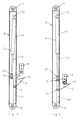
- La figure 1Figure 1
- est une vue en perspective d'un dispositif selon l'invention.is a perspective view of a device according to the invention.
- La figure 2Figure 2
- est une vue en élévation latérale correspondant sensiblement à celle de la figure 1, c'est-à-dire sans accrochage de la broche de la barre ou tringle de la toile dans le dispositif de verrouillage.is a side elevation view substantially corresponding to that of the Figure 1, that is to say without hooking the bar pin or canvas rod in the locking device.
- La figure 3Figure 3
- est une vue correspondante à la figure 2 dans la position verrouillée avec mise sous tension de la toile.is a view corresponding to FIG. 2 in locked position with power on canvas tension.
Les éléments caractéristiques de l'invention sont repris dans les revendications annexées.The characteristic elements of the invention are set out in the appended claims.
Selon l'invention, un premier dispositif de verrouillage est disposé latéralement et extérieurement près d'un bord latéral de la toile. Un deuxième dispositif symétrique est prévu pour être disposé de l'autre côté, et les deux dispositifs sont donc perpendiculaires à la barre ou tringle (non représentée) de la toile (également non représentée).According to the invention, a first device for locking is arranged laterally and externally near a side edge of the canvas. A second device symmetrical is intended to be placed on the other side, and the two devices are therefore perpendicular to the bar or rod (not shown) of the canvas (also not shown).
Chacun de ces dispositifs est constitué par
un boítier 2 comportant respectivement à chaque extrémité
une première pièce de fixation 1 et une deuxième pièce de
fixation 8. Le boítier 2 contient un ressort de pression 3
connu en soi, par exemple sous forme d'un corps de cylindre
31 fixé dans le boítier 2 à son extrémité supérieure de
manière à pouvoir pivoter en 32, et comportant une tige 33
se terminant par une pièce de liaison 34 sur laquelle est
montée une pièce de verrouillage 5.Each of these devices is made up of
a
Le boítier 2, à sa partie inférieure,
comporte un passage rétréci ou puits 21.The
Sur la pièce de verrouillage 5, est monté au
moins un galet ou un jeu de galets 6 et de préférence deux
galets en tandem. L'axe de montage de ces galets maintient
également l'extrémité de la pièce de verrouillage 5 en
permettant son pivotement.On the
Au moins un deuxième galet ou un deuxième jeu
de galets 7 est également monté sur la pièce de
verrouillage 5. Le diamètre aussi bien des galets 6 que des
galets 7 est tel qu'ils peuvent pénétrer dans la partie
inférieure rétrécie ou puits 21 du boítier 2.At least a second roller or a
Des moyens équivalents aux galets tels que des patins de glissement peuvent bien entendu être utilisés.Means equivalent to pebbles such as sliding shoes can of course be used.
Une fente longitudinale dans le boítier 2
(voir figure 1) est prévue pour qu'une partie saillante de
la pièce de verrouillage 5 puisse sortir du boítier 2 et
puisse glisser depuis la position représentée dans la
figure 1, vers le bas. Cette partie saillante extérieure de
la pièce de verrouillage 5 est pourvue d'un bec 51.A longitudinal slot in the housing 2
(see Figure 1) is provided so that a projecting part of
the
On notera que la forme de la partie
intérieure de la pièce de verrouillage 5 qui porte les
galets 6 et 7, est adaptée au mouvement prévu des galets 6
et 7 depuis la position de la figure 1 vers celle de la
figure 2.Note that the shape of the part
inside of the
Dans la position des figures 1 et 2, le galet
ou le jeu de galets 6 vient buter sur la partie rétrécie 21
du boítier 2, et le galet ou jeu de galets 7 est déjà
engagée dans cette partie rétrécie ou puits 21 du boítier
2. In the position of Figures 1 and 2, the roller
or the set of
Lorsqu'une broche 9, qui est fixée sur la
barre ou tringle de la toile, approche de la fin de sa
course, elle pénètre dans le bec 51 et fait basculer la
pièce d'accrochage 5 qui pivote par rapport au galet ou jeu
de galets 7 et amène le galet ou jeu de galets 6 vers le
puits 21 du boítier 2 où ce galet ou jeu de galets 6
s'engage sous l'effet du ressort de pression 3 en tendant
ainsi fortement la toile.When a
Comparé à la solution préconisée dans le
document DE-196 36 359 où c'est la pièce de verrouillage
qui sous l'effet du ressort de pression, bloque la toile en
position tendue, selon le mode d'exécution préconisé par la
présente demande, c'est le ressort de pression qui agit
directement sur la pièce 5 qui maintient la toile tendue
mais pas nécessairement immobile. Sous l'action du vent,
cette toile peut bouger légèrement contre l'effort du
ressort de pression, ce qui réduit le bruit occasionné par
le vent.Compared to the solution recommended in the
document DE-196 36 359 where it is the locking piece
which under the effect of the pressure spring, blocks the canvas in
stretched position, according to the mode of execution recommended by the
present request, it is the pressure spring which acts
directly on
Un mouvement inverse contre l'effort du ressort de pression 3 (lorsque l'on enroule la toile, soit manuellement, soit à l'aide d'un moteur électrique par exemple), ramène le galet ou jeu de galets 6 dans la position des figures 1 et 2 et permet ensuite l'enroulement élastique de la toile sous l'effet du ressort.A reverse movement against the effort of the pressure spring 3 (when the canvas is rolled up, manually, either using an electric motor by example), bring the roller or roller set 6 back into the position of Figures 1 and 2 and then allows the winding elastic of the canvas under the effect of the spring.
On dispose donc d'un moyen simple et efficace qui permet de tendre la toile en position déployée et de la verrouiller tout en permettant l'enroulement de celle-ci sans tension trop importante lorsque le dispositif est déverrouillé.So we have a simple and effective way which allows you to stretch the canvas in the deployed position and lock while allowing the winding thereof without too much tension when the device is unlocked.
L'ensemble est peu encombrant, et le ressort
de pression 3 est reçu dans un boítier de protection.The whole is compact, and the
Il convient de noter qu'une inversion des
dispositions relatives du dispositif de verrouillage et de
la barre ou tringle de la toile est envisageable, en ce
sens que le boítier 2 soit fixé ou logé dans ou sur cette
barre et que la broche 9 soit solidaire du dispositif de
guidage latéral de la toile.It should be noted that an inversion of the
relative provisions of the locking device and
the bar or rod of the canvas is possible, in this
sense that the
Ainsi qu'il a été indiqué, un dispositif symétrique est prévu sur le côté opposé de la toile. Dans le cas où, pour une façade, on envisage de prévoir au moins deux toiles disposées côte à côte, il est bien entendu possible de coupler en un seul élément deux dispositifs de du type précité, l'un assurant le maintien du côté droit d'une première toile et l'autre du côté gauche de la toile voisine, et ceci de manière répétitive si plus de deux toiles sont envisagées.As indicated, a device symmetrical is provided on the opposite side of the canvas. In the case where, for a facade, it is envisaged to provide at least two fabrics arranged side by side, it is understood two devices can be combined in a single element of the aforementioned type, one ensuring the maintenance of the right side of a first canvas and the other on the left side of the canvas neighbor, and this repeatedly if more than two canvases are being considered.
La caractéristique essentielle du dispositif de l'invention par rapport aux formes déjà connues est la bonne protection du ressort de pression et des pivots du dispositif dans un boítier. Par rapport aux solutions connues par l'état de la technique, le système est surtout beaucoup moins bruyant sous l'effet du vent tout en gardant la toile tendue dans la position déployée.The essential feature of the device of the invention compared to already known forms is the good protection of the pressure spring and pivots of the device in a case. Compared to solutions known from the state of the art, the system is above all much less noisy under the effect of the wind while keeping the stretched fabric in the deployed position.
Claims (6)
Priority Applications (3)
| Application Number | Priority Date | Filing Date | Title |
|---|---|---|---|
| DE69828792T DE69828792D1 (en) | 1998-11-06 | 1998-11-06 | Device for fixing and locking externally mounted blinds or sunshades |
| EP98870242A EP0999319B1 (en) | 1998-11-06 | 1998-11-06 | Holding and locking device intended for an external blind or a sun protection awning |
| AT98870242T ATE288004T1 (en) | 1998-11-06 | 1998-11-06 | DEVICE FOR FASTENING AND LOCKING FOR EXTERNALLY MOUNTED BLINDS OR SUN PROTECTION AWNINGS |
Applications Claiming Priority (1)
| Application Number | Priority Date | Filing Date | Title |
|---|---|---|---|
| EP98870242A EP0999319B1 (en) | 1998-11-06 | 1998-11-06 | Holding and locking device intended for an external blind or a sun protection awning |
Publications (2)
| Publication Number | Publication Date |
|---|---|
| EP0999319A1 true EP0999319A1 (en) | 2000-05-10 |
| EP0999319B1 EP0999319B1 (en) | 2005-01-26 |
Family
ID=8237113
Family Applications (1)
| Application Number | Title | Priority Date | Filing Date |
|---|---|---|---|
| EP98870242A Expired - Lifetime EP0999319B1 (en) | 1998-11-06 | 1998-11-06 | Holding and locking device intended for an external blind or a sun protection awning |
Country Status (3)
| Country | Link |
|---|---|
| EP (1) | EP0999319B1 (en) |
| AT (1) | ATE288004T1 (en) |
| DE (1) | DE69828792D1 (en) |
Cited By (2)
| Publication number | Priority date | Publication date | Assignee | Title |
|---|---|---|---|---|
| WO2004048715A1 (en) * | 2002-11-22 | 2004-06-10 | Llaza, Sa | Vertical awning comprising an automatic device for the taut fixing thereof in the partially or totally extended position |
| US8316910B2 (en) | 2005-08-26 | 2012-11-27 | Dometic Llc | Awning assemblies |
Citations (6)
| Publication number | Priority date | Publication date | Assignee | Title |
|---|---|---|---|---|
| DE2728121A1 (en) | 1977-06-22 | 1979-01-11 | Ade Werk Gmbh | Exposed sunblind bottom vertically track guided rod - has end pawls moving and locked in track notch serrations |
| DE3448263C2 (en) | 1984-03-01 | 1990-04-05 | Thomas 1000 Berlin De Grahn | Rotary closure lever |
| DE4427298A1 (en) | 1994-08-02 | 1996-02-15 | Warema Renkhoff Gmbh & Co Kg | Method of clamping sun blind in extended position |
| DE19536359A1 (en) | 1995-09-29 | 1997-04-10 | Heidelberger Druckmasch Ag | Printing machine and method for sheet transport along several forme cylinders |
| EP0801185A2 (en) * | 1996-04-13 | 1997-10-15 | WAREMA Renkhoff GmbH | Vertical awning wind fixing device |
| DE19636359A1 (en) | 1996-09-06 | 1998-03-12 | Siegfried Woitkowitz | Three |
-
1998
- 1998-11-06 DE DE69828792T patent/DE69828792D1/en not_active Expired - Lifetime
- 1998-11-06 AT AT98870242T patent/ATE288004T1/en not_active IP Right Cessation
- 1998-11-06 EP EP98870242A patent/EP0999319B1/en not_active Expired - Lifetime
Patent Citations (6)
| Publication number | Priority date | Publication date | Assignee | Title |
|---|---|---|---|---|
| DE2728121A1 (en) | 1977-06-22 | 1979-01-11 | Ade Werk Gmbh | Exposed sunblind bottom vertically track guided rod - has end pawls moving and locked in track notch serrations |
| DE3448263C2 (en) | 1984-03-01 | 1990-04-05 | Thomas 1000 Berlin De Grahn | Rotary closure lever |
| DE4427298A1 (en) | 1994-08-02 | 1996-02-15 | Warema Renkhoff Gmbh & Co Kg | Method of clamping sun blind in extended position |
| DE19536359A1 (en) | 1995-09-29 | 1997-04-10 | Heidelberger Druckmasch Ag | Printing machine and method for sheet transport along several forme cylinders |
| EP0801185A2 (en) * | 1996-04-13 | 1997-10-15 | WAREMA Renkhoff GmbH | Vertical awning wind fixing device |
| DE19636359A1 (en) | 1996-09-06 | 1998-03-12 | Siegfried Woitkowitz | Three |
Cited By (2)
| Publication number | Priority date | Publication date | Assignee | Title |
|---|---|---|---|---|
| WO2004048715A1 (en) * | 2002-11-22 | 2004-06-10 | Llaza, Sa | Vertical awning comprising an automatic device for the taut fixing thereof in the partially or totally extended position |
| US8316910B2 (en) | 2005-08-26 | 2012-11-27 | Dometic Llc | Awning assemblies |
Also Published As
| Publication number | Publication date |
|---|---|
| ATE288004T1 (en) | 2005-02-15 |
| EP0999319B1 (en) | 2005-01-26 |
| DE69828792D1 (en) | 2005-03-03 |
Similar Documents
| Publication | Publication Date | Title |
|---|---|---|
| EP0538106B1 (en) | Motor-blind of the roller-type for curved window | |
| CA2487812C (en) | Device with shutter winding about a drum | |
| CA2675648C (en) | Device with a winding curtain | |
| FR2588307A1 (en) | Motorised screen device | |
| EP2000340B1 (en) | Vehicle concealment device with swinging arms linked through cable and corresponding vehicle. | |
| EP2277083B1 (en) | Projector screen equipped with means for applying vertical and horizontal tensile forces | |
| EP0999319B1 (en) | Holding and locking device intended for an external blind or a sun protection awning | |
| EP0136351A1 (en) | Method and device for covering with tarpaulin particularly vehicles | |
| FR2594480A1 (en) | Retractable screen device | |
| EP1619078A1 (en) | Vehicle boot cover and vehicle equipped therewith | |
| EP0818602B1 (en) | Device for winding and unwinding a fabric | |
| EP0531274B1 (en) | Fixing device of a screen on a roller | |
| FR2631374A1 (en) | Roller blind for window of parallelogram form - has screw and ball nut to move blind roller axially as it is rotated | |
| FR3137936A1 (en) | Basin covering system equipped with cover plating mechanism | |
| EP1157870A1 (en) | Roller blind with axially mobile pull bar | |
| EP1336519B1 (en) | Roller blind for motor vehicle with pull bar comprising a mobile cover | |
| EP2199486A1 (en) | Florentine blind, of the type with a case | |
| CH628393A5 (en) | Roller shutter | |
| FR2782103A1 (en) | Flexible membrane shade for covering glassed surface, has membrane wound and unwound on shaft which is in turn mounted on slidable bearings | |
| BE1017125A6 (en) | Device roller curtain. | |
| FR3143051A1 (en) | ASSISTANCE DEVICE FOR THE INSTALLATION OF OCCULTANT DEVICES | |
| FR2964140B1 (en) | AWNING COMPRISING A WHEEL THAT CAN BE WRAPPED AND CORRESPONDING WHEEL | |
| FR2805305A1 (en) | Cable slack take up for vertically retracting door comprises grooved rollers acting as return and tensioner parts for cable | |
| FR2733274A1 (en) | Roller blind for railway carriages | |
| FR2811705A1 (en) | ROLLER SHUTTER COMPRISING MEANS FOR LOCKING THE WINDING SHAFT OF ITS APRON |
Legal Events
| Date | Code | Title | Description |
|---|---|---|---|
| PUAI | Public reference made under article 153(3) epc to a published international application that has entered the european phase |
Free format text: ORIGINAL CODE: 0009012 |
|
| AK | Designated contracting states |
Kind code of ref document: A1 Designated state(s): AT BE CH DE DK ES FR GB IT LI LU NL SE |
|
| AX | Request for extension of the european patent |
Free format text: AL;LT;LV;MK;RO;SI |
|
| 17P | Request for examination filed |
Effective date: 20000609 |
|
| AKX | Designation fees paid |
Free format text: AT BE CH DE DK ES FR GB IT LI LU NL SE |
|
| GRAP | Despatch of communication of intention to grant a patent |
Free format text: ORIGINAL CODE: EPIDOSNIGR1 |
|
| GRAS | Grant fee paid |
Free format text: ORIGINAL CODE: EPIDOSNIGR3 |
|
| RTI1 | Title (correction) |
Free format text: HOLDING AND LOCKING DEVICE INTENDED FOR AN EXTERNAL BLIND OR A SUN PROTECTION AWNING |
|
| GRAA | (expected) grant |
Free format text: ORIGINAL CODE: 0009210 |
|
| AK | Designated contracting states |
Kind code of ref document: B1 Designated state(s): AT BE CH DE DK ES FR GB IT LI LU NL SE |
|
| PG25 | Lapsed in a contracting state [announced via postgrant information from national office to epo] |
Ref country code: NL Free format text: LAPSE BECAUSE OF FAILURE TO SUBMIT A TRANSLATION OF THE DESCRIPTION OR TO PAY THE FEE WITHIN THE PRESCRIBED TIME-LIMIT Effective date: 20050126 Ref country code: IT Free format text: LAPSE BECAUSE OF FAILURE TO SUBMIT A TRANSLATION OF THE DESCRIPTION OR TO PAY THE FEE WITHIN THE PRESCRIBED TIME-LIMIT;WARNING: LAPSES OF ITALIAN PATENTS WITH EFFECTIVE DATE BEFORE 2007 MAY HAVE OCCURRED AT ANY TIME BEFORE 2007. THE CORRECT EFFECTIVE DATE MAY BE DIFFERENT FROM THE ONE RECORDED. Effective date: 20050126 Ref country code: GB Free format text: LAPSE BECAUSE OF FAILURE TO SUBMIT A TRANSLATION OF THE DESCRIPTION OR TO PAY THE FEE WITHIN THE PRESCRIBED TIME-LIMIT Effective date: 20050126 Ref country code: AT Free format text: LAPSE BECAUSE OF FAILURE TO SUBMIT A TRANSLATION OF THE DESCRIPTION OR TO PAY THE FEE WITHIN THE PRESCRIBED TIME-LIMIT Effective date: 20050126 |
|
| REG | Reference to a national code |
Ref country code: GB Ref legal event code: FG4D Free format text: NOT ENGLISH |
|
| REG | Reference to a national code |
Ref country code: CH Ref legal event code: EP |
|
| REF | Corresponds to: |
Ref document number: 69828792 Country of ref document: DE Date of ref document: 20050303 Kind code of ref document: P |
|
| PG25 | Lapsed in a contracting state [announced via postgrant information from national office to epo] |
Ref country code: SE Free format text: LAPSE BECAUSE OF FAILURE TO SUBMIT A TRANSLATION OF THE DESCRIPTION OR TO PAY THE FEE WITHIN THE PRESCRIBED TIME-LIMIT Effective date: 20050426 Ref country code: DK Free format text: LAPSE BECAUSE OF FAILURE TO SUBMIT A TRANSLATION OF THE DESCRIPTION OR TO PAY THE FEE WITHIN THE PRESCRIBED TIME-LIMIT Effective date: 20050426 |
|
| PG25 | Lapsed in a contracting state [announced via postgrant information from national office to epo] |
Ref country code: DE Free format text: LAPSE BECAUSE OF FAILURE TO SUBMIT A TRANSLATION OF THE DESCRIPTION OR TO PAY THE FEE WITHIN THE PRESCRIBED TIME-LIMIT Effective date: 20050427 |
|
| PG25 | Lapsed in a contracting state [announced via postgrant information from national office to epo] |
Ref country code: ES Free format text: LAPSE BECAUSE OF FAILURE TO SUBMIT A TRANSLATION OF THE DESCRIPTION OR TO PAY THE FEE WITHIN THE PRESCRIBED TIME-LIMIT Effective date: 20050507 |
|
| NLV1 | Nl: lapsed or annulled due to failure to fulfill the requirements of art. 29p and 29m of the patents act | ||
| GBV | Gb: ep patent (uk) treated as always having been void in accordance with gb section 77(7)/1977 [no translation filed] |
Effective date: 20050126 |
|
| PG25 | Lapsed in a contracting state [announced via postgrant information from national office to epo] |
Ref country code: LU Free format text: LAPSE BECAUSE OF NON-PAYMENT OF DUE FEES Effective date: 20051130 Ref country code: LI Free format text: LAPSE BECAUSE OF NON-PAYMENT OF DUE FEES Effective date: 20051130 Ref country code: CH Free format text: LAPSE BECAUSE OF NON-PAYMENT OF DUE FEES Effective date: 20051130 Ref country code: BE Free format text: LAPSE BECAUSE OF NON-PAYMENT OF DUE FEES Effective date: 20051130 |
|
| PLBE | No opposition filed within time limit |
Free format text: ORIGINAL CODE: 0009261 |
|
| STAA | Information on the status of an ep patent application or granted ep patent |
Free format text: STATUS: NO OPPOSITION FILED WITHIN TIME LIMIT |
|
| 26N | No opposition filed |
Effective date: 20051027 |
|
| REG | Reference to a national code |
Ref country code: CH Ref legal event code: PL |
|
| PG25 | Lapsed in a contracting state [announced via postgrant information from national office to epo] |
Ref country code: FR Free format text: LAPSE BECAUSE OF NON-PAYMENT OF DUE FEES Effective date: 20060731 |
|
| REG | Reference to a national code |
Ref country code: FR Ref legal event code: ST Effective date: 20060731 |
|
| BERE | Be: lapsed |
Owner name: HAROL INTERNATIONAL N.V. Effective date: 20051130 |